![]() ASSEMBLY INSTRUCTIONS
ASSEMBLY INSTRUCTIONS
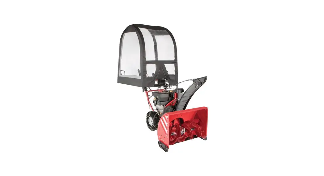
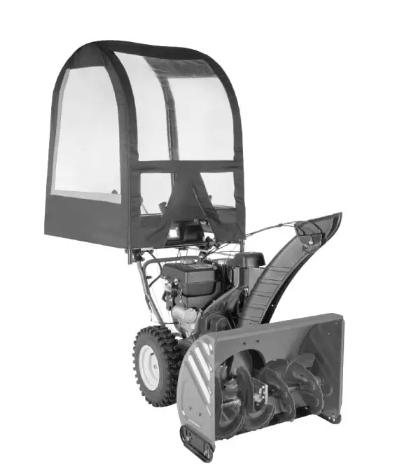
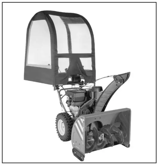
DELUXE UNIVERSAL SNOW THROWER CAB
490-241-0032
Scan the Microsoft Tag Below
Follow the steps below to launch your Arnold Snow Thrower Cab installation video.
Step 1: Download the free Microsoft Tag reader application for your smartphone at gettag.mobi
Step 2: Scan the Tag below with your smartphone.
![]() Get the free mobile app at:
Get the free mobile app at:
http://gettag.mobi
PARTS IDENTIFICATION PAGE
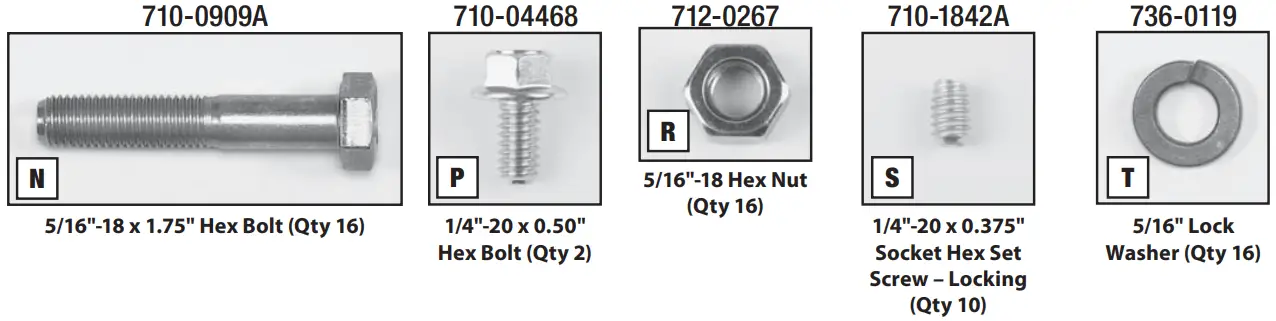
Hardware Included: Hardware showed actual size.
Note: Your kit may have excess hardware.
 | 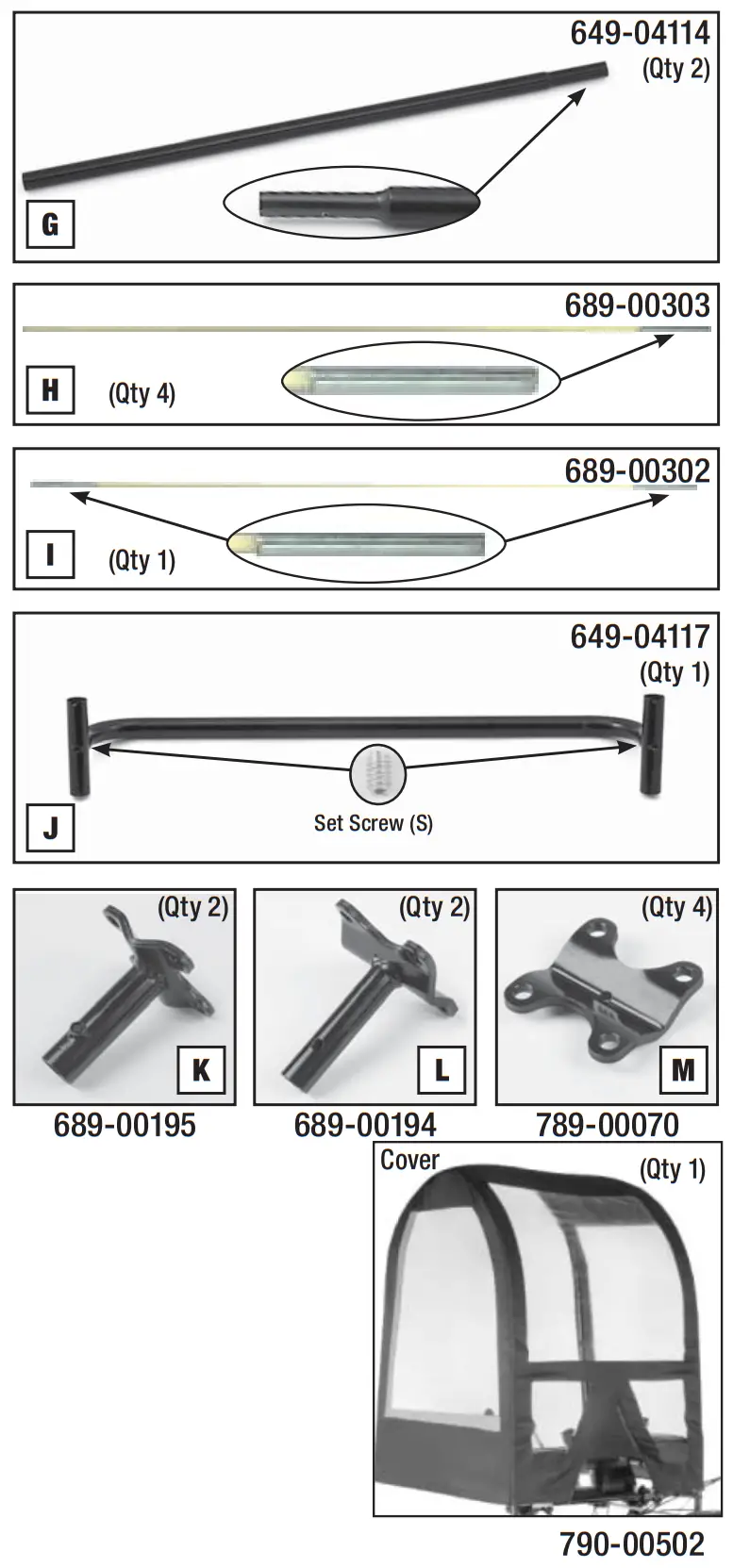 |
Do NOT return to store. For missing parts or services, call 1-800-228-9683
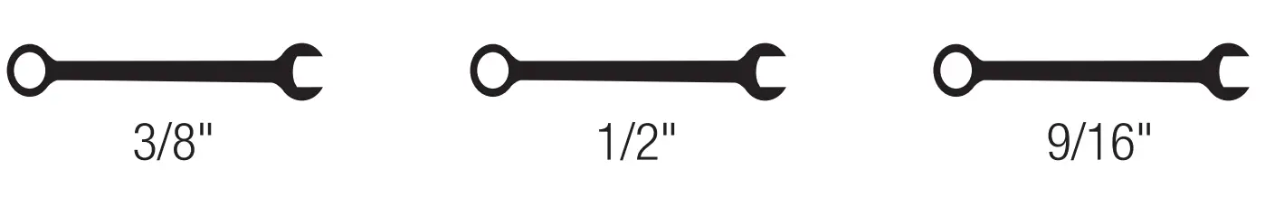
Tools Required:
3/8,” 9/16″ and 1/2″ box wrenches (not included);Allen wrench (included).
 CAUTION: WEARING SAFETY GLASSES IS RECOMMENDED DURING ASSEMBLY.
Assistance from another person is recommended for certain steps.
Refer to the parts identification sheet to ensure you have all the necessary parts.
Assembly Instructions:
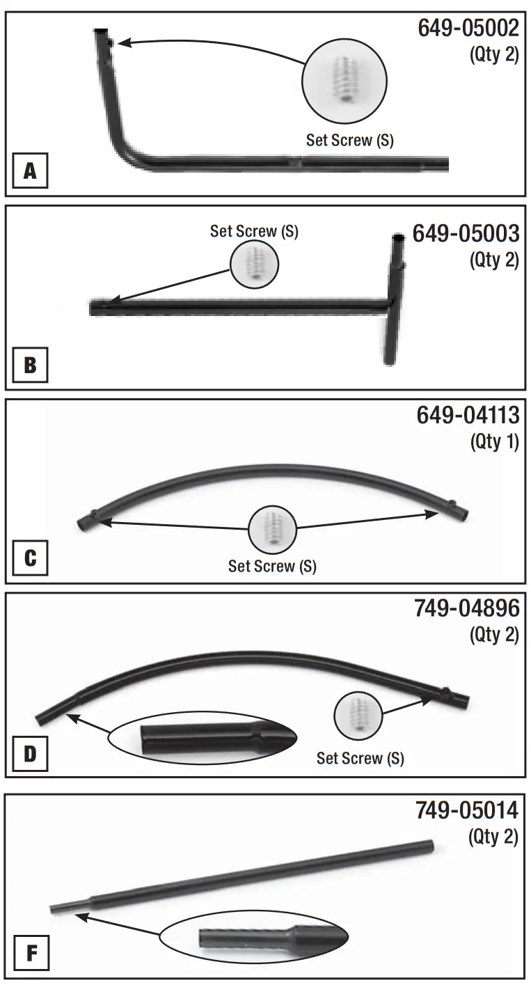
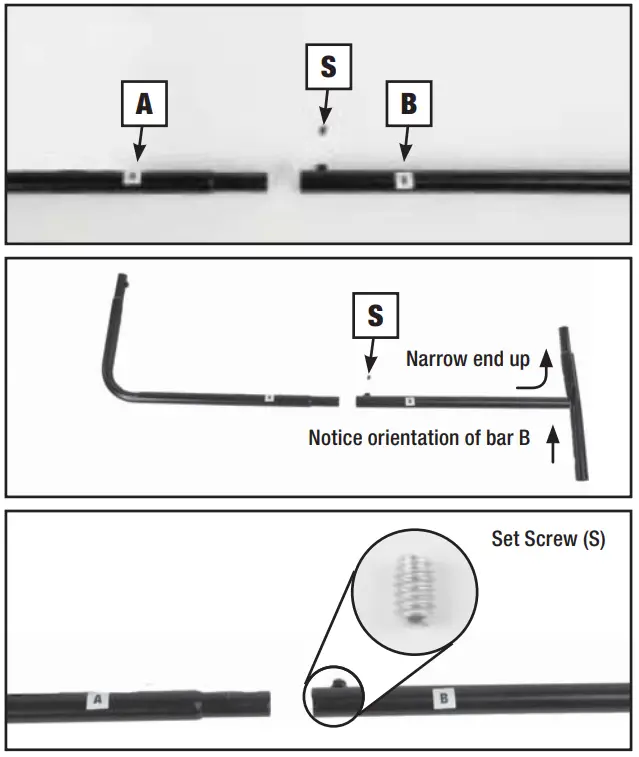
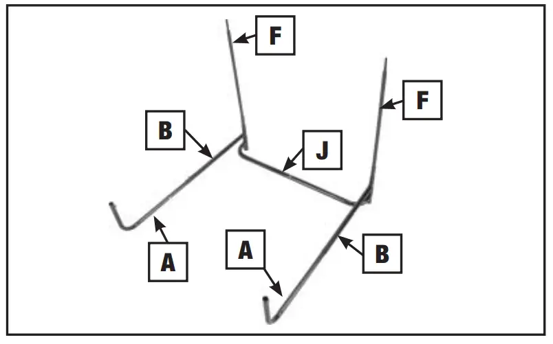
- Lay sets of bars A & B on a flat surface. Slides A & B are all the way together. Insert set screw (S) into the end of bar B, securing fi nger-tight. Repeat with another set of bars A & B.
NOTE: Do not tighten set screw (S) using Allen wrench until the entire frame is assembled.
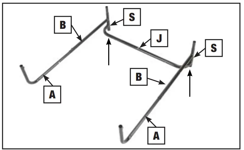
- Attach bar J to the B end of the A/B assemblies (See arrows). Insert set screws (S) into bar J, securing in finger-tight.

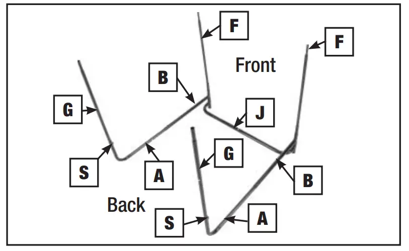
- Insert poles F, narrow end up, into the union of bars J, A/B.

- Insert poles G, narrow end up, into A end of both A/B assemblies. Insert set screw (S) into the top of bars A, securing in finger-tight.

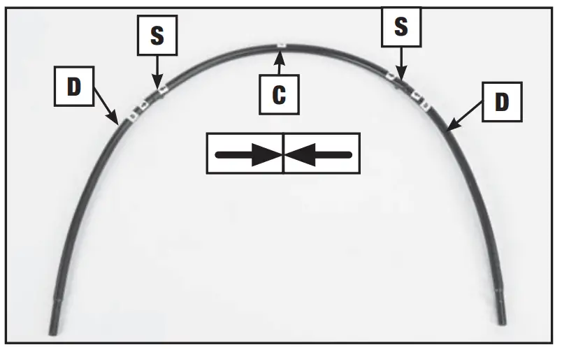
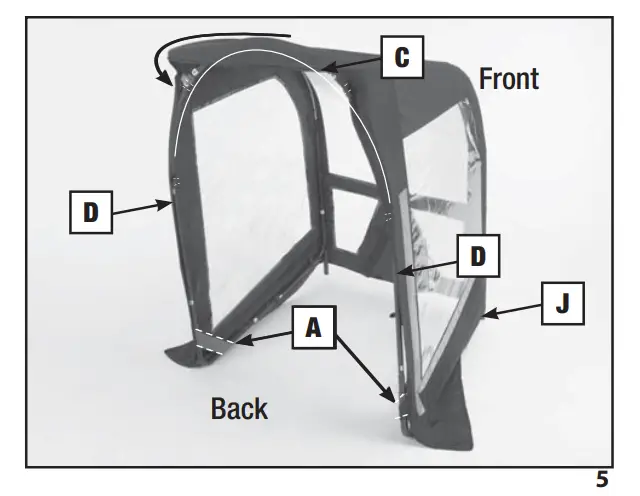
- Place curved bar C on a flat surface, nuts facing up. Insert the labeled end of curved bar D into C (making sure arrows meet). Repeat with the other bar D on the opposite end of bar C. Insert set screw (S) into ends of bars C, securing in finger-tight.

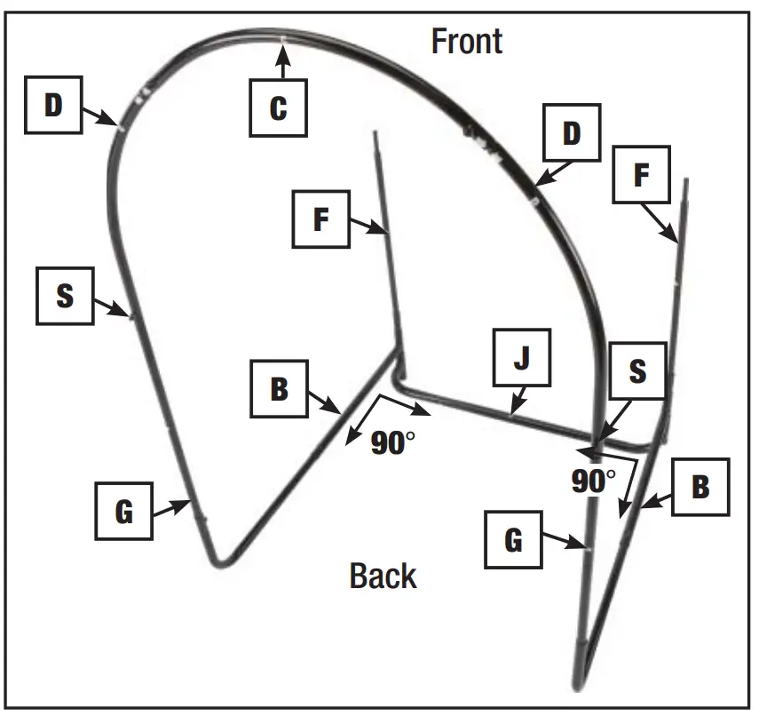
- Place assembly D/C/D onto ends of poles G. Insert set screw (S) at the bottom of poles D, securing in fi nger-tight.

- Make sure the cab frame is in the shape of a box, with right angles (90°). Then tighten all the set screws (S), except the set screws (S) on the crossbar (J), using the enclosed Allen wrench.
CAUTION: Do not over-tighten the set screws.
NOTE: For steps 8, 9 & 10, please be sure you wear safety glasses .
.
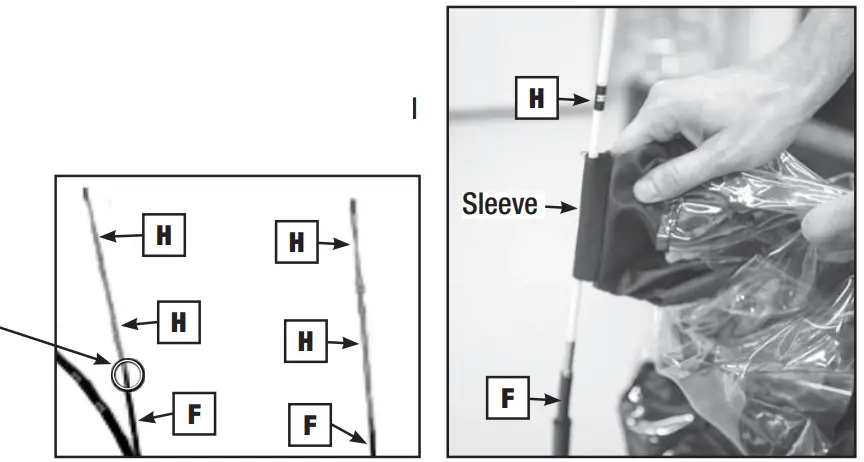
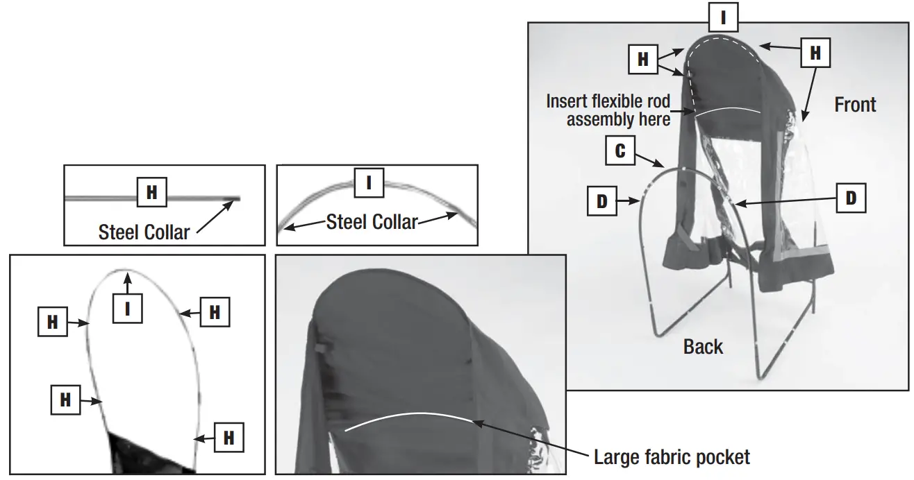
NOTE: You should have four H rods and one I rod. - Pull the cover out of the box and locate the inside sleeves. Insert the steel collar ends of these H rods into the tops of poles F. The cover will be hanging loosely in the rod/pole assembly. Feed one H rod through one sleeve of the cover, then repeat with another H rod on the other side.
NOTE: Flexible H rods will feel loose when inserted. This is correct. Do not attempt to force flexible H rods further into poles F.
- Slide the two remaining H rods over the previously inserted H rods. Take rod I and insert the ends of the H rods into the steel collar ends of rod I. Pull the cover-up over the rod assembly and slide the top of the rod assembly into the large fabric pocket inside the cover. This will require some bending of the rods.

- Pull the cab material down and back towards the arch assembly, D/C/D. Fasten hook-and-loop straps on both sides of the D/C/D assembly. Slide elastic loops over the rear corner of bar A on both sides. Fasten hook-and-loop straps around all bars at various locations. (For your convenience you may want to wait until the cab is mounted on your snow thrower to finish fastening these straps.) After the material is secured over the frame assembly, remove bar J.

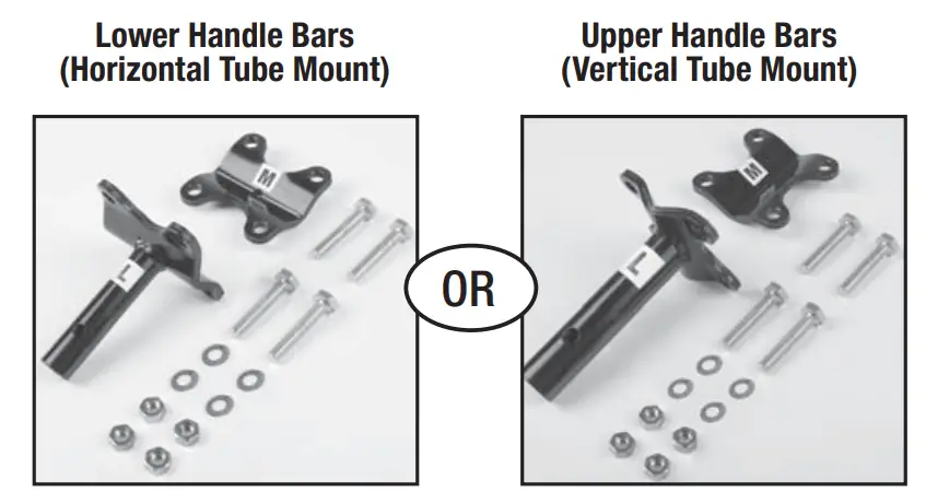
- Your clamps can be partially pre-assembled.
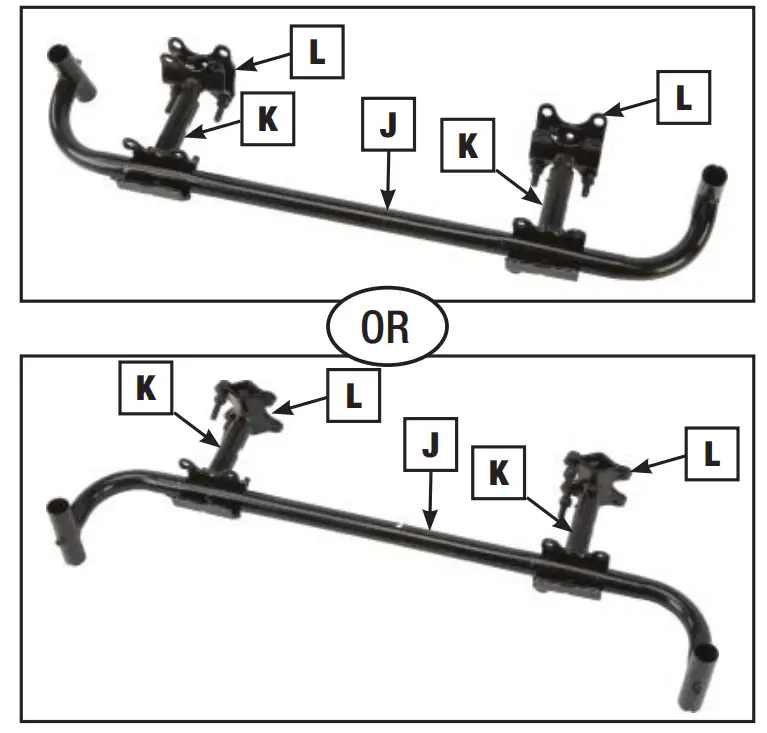
The clamp assembly that mounts to your unit may be oriented horizontally or vertically. The preferred orientation of the clamp assembly is to have the saddles perpendicular to one another. Thread the small bolt P into the center of K & L assemblies, finger tight. Slide smaller tube, L, into the larger tube, K.
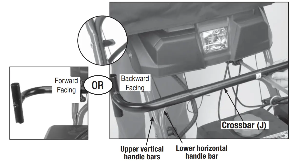
- To determine the general location and direction for the crossbar (J), have an assistant hold the cab at the desired location over the unit.
NOTE: Depending on your unit, the crossbar may be positioned facing forward or backward, and above or below any linkage.
- Notice how the crossbar will sit in clamp assemblies once clamps are mounted on the unit.
NOTE: If the controls on your snow thrower require more space for proper operation, fl ip bar J.
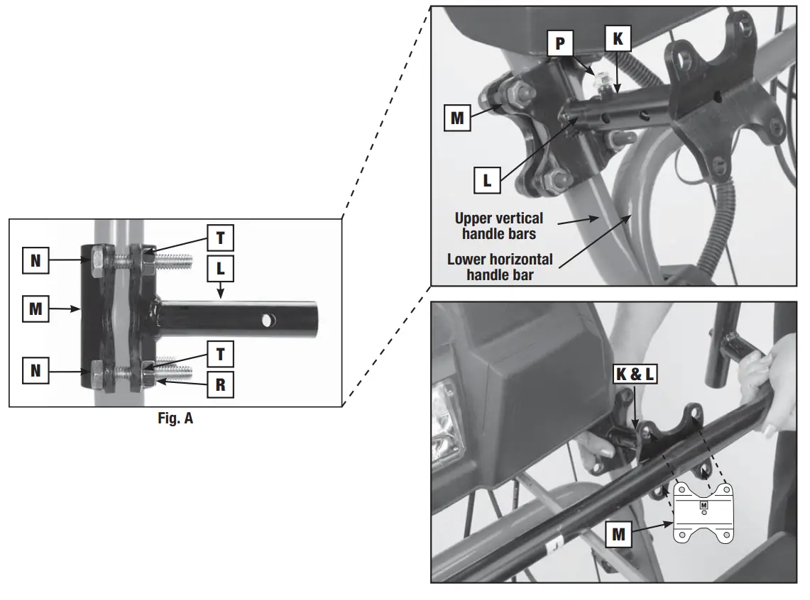
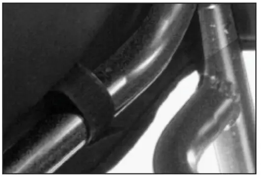
- Holding crossbar (J) in the desired location, select area to mount K & L clamp assemblies. See Fig. 12.
NOTE: Brute and John Deere units may require you to mount to the horizontal handlebars on the unit.
NOTE: Preferred position is on the vertical portion of the unit’s upper handlebars. - Take pre-assembled K, L & M clamp assemblies. Mount assemblies K & L in the determined location on the unit. Use plates M and large bolts N, lock washer T, and nuts R to secure K, L & M assemblies to the unit. Now tighten small bolt P so both clamp assemblies extend the equal distance from the frame.
NOTE: Location of lock washer T should be underneath nut R.
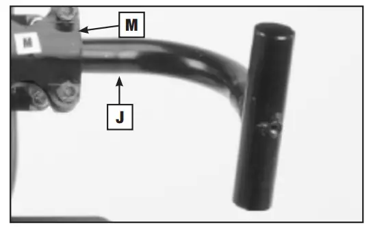
- Place crossbar (J) against assembly K & L. Center crossbar (J) against the unit. Use two remaining M plates, large bolts N, lock washer T, and nuts R to secure the crossbar. See Figure 15A.

- Fully insert the ends of the front of the cab assembly into the ends of the crossbar (J). Insert set screws (S) into ends of the crossbar (J). With assistant holding cab assembly horizontal to the ground, tighten all bolts and set screws.
CAUTION: Do not overtighten the set screws.
- Finish assembly by fastening all hook-and-loop straps inside the cab if you have not already done so.
CAUTION: No cab fabric should be allowed to touch the engine or exhaust.
- The cab is designed to accommodate snow throwers equipped with a light. A zipper on the front of the cab can be opened and the flap pulled back to allow the light to shine through. At this time, adjustments may be necessary for the free movement of operation controls.

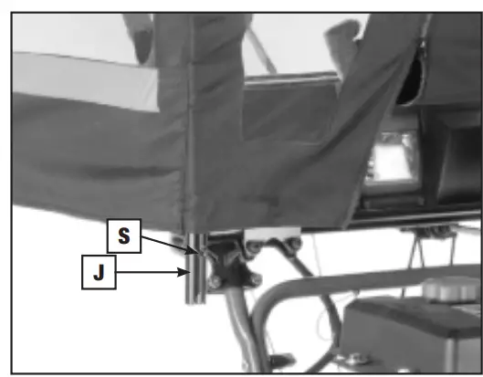
- For storage, loosen the two set screws (S) in crossbar “J” and pull the cab up and out of crossbar “J.” See Figure 17.
- For cleaning, just use mild soap and water.
 .
.
 The preferred orientation of the clamp assembly is to have the saddles perpendicular to one another. Thread the small bolt P into the center of K & L assemblies, finger tight. Slide smaller tube, L, into the larger tube, K.
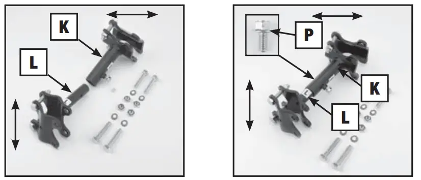
MANUFACTURER’S LIMITED WARRANTY FOR

The limited warranty set forth below is given by MTD LLC with respect to new merchandise purchased and used in the United States and/or its territories and possessions and by MTD Products Limited with respect to new merchandise purchased and used in Canada and/or its territories and possessions (either entity respectively, “MTD”).
“MTD” warrants this product (excluding its Normal Wear Parts and Attachments as described below) against defects in material and workmanship for a period of one (1) year commencing on the date of original purchase and will, at its option, repair or replace, free of charge, any part found to be defective in materials or workmanship. This limited warranty shall only apply if this product has been operated and maintained in accordance with the Operator’s Manual furnished with the product, and has not been subject to misuse, abuse, commercial
use neglect, accident, improper maintenance, alteration, vandalism, theft, fire, water, or damage because of other peril or natural disaster.
Damage resulting from the installation or use of any part, accessory, or attachment not approved by MTD for use with the product(s) covered by this manual will void your warranty as to any resulting damage. Normal Wear Parts are warranted to be free from defects in material and workmanship for a period of thirty (30) days from the date of purchase.
Normal wear parts include but are not limited to items such as:
batteries, belts, blades, blade adapters, tines, grass bags, wheels, rider deck wheels, seats, snow thrower skid shoes, friction wheels, shave plates, auger spiral rubber, and tires. Attachments — MTD warrants attachments for this product against defects in material and workmanship for a period of one (1) year, commencing on the date of the attachment’s original purchase or lease. Attachments include, but are not limited to items such as grass collectors and mulch kits.
HOW TO OBTAIN SERVICE: Warranty service is available, WITH PROOF
OF PURCHASE, through your local authorized service dealer. To locate
the dealer in your area:
In the U.S.A.
Check your Yellow Pages, or contact MTD LLC at P.O. Box 361131,
Cleveland, Ohio 44136-0019, or call 1-800-800-7310, 1-330-220- 4683 or log on to our Web site at www.mtdproducts.com.
In Canada
Contact MTD Products Limited, Kitchener, ON N2G 4J1, or call 1-800-668-1238 or log on to our Web site at www.mtdcanada.com.
This limited warranty does not provide coverage in the following cases:
a. Log splitter pumps, valves, and cylinders have a separate one-year warranty.
b. Routine maintenance items such as lubricants, filters, blade sharpening, tune-ups, brake adjustments, clutch adjustments, deck adjustments, and normal deterioration of the exterior finish due to use or exposure.
c. Service completed by someone other than an authorized service dealer.
d. MTD does not extend any warranty for products sold or exported outside of the United States and/or Canada, and their respective possessions and territories, except those sold through MTD’s authorized channels of export distribution.
e. Replacement parts that are not genuine MTD parts.
f. Transportation charges and service calls.
g MTD does not warrant this product for commercial use.
No implied warranty, including any implied warranty of merchantability or fitness for a particular purpose, applies after the applicable period of an express written warranty above as to the parts as identified. No other express warranty, whether written or oral, except as mentioned above, given by any person or entity, including a dealer or retailer, with respect to any product, shall bind MID. During the period of the warranty, the exclusive remedy is repair or replacement of the product as set forth above.
The provisions as set forth in this warranty provide the sole and exclusive remedy arising from the sale. MTD shall not be liable for incidental or consequential loss or damage including, without limitation, expenses incurred for substitute or replacement lawn care services or for rental expenses to temporarily replace a warranted product.
Some states do not allow the exclusion or limitation of incidental or consequential damages, or limitations on how long an implied warranty lasts, so the above exclusions or limitations may not apply to you.
In no event shall recovery of any kind be greater than the amount of the purchase price of the product sold. Alteration of safety features of the product shall void this warranty. You assume the risk and liability for loss, damage, or injury to you and your property and/or to others and their property arising out of the misuse or inability to use the product.
This limited warranty shall not extend to anyone other than the original purchaser or to the person for whom it was purchased as a gift.
HOW STATE LAW RELATES TO THIS WARRANTY: This limited warranty gives you specific legal rights, and you may also have other rights which vary from state to state.
IMPORTANT: The owner may be required to present proof of purchase to obtain warranty coverage.
![]()
MTD LLC, P.O. BOX 361131 CLEVELAND, OHIO 44136-0019; Phone: 1-800-800-7310, 1-330-220-4683
MTD Canada Limited – KITCHENER, ON N2G 4J1; Phone 1-800-668-1238
GDOC-100167 REV. A


