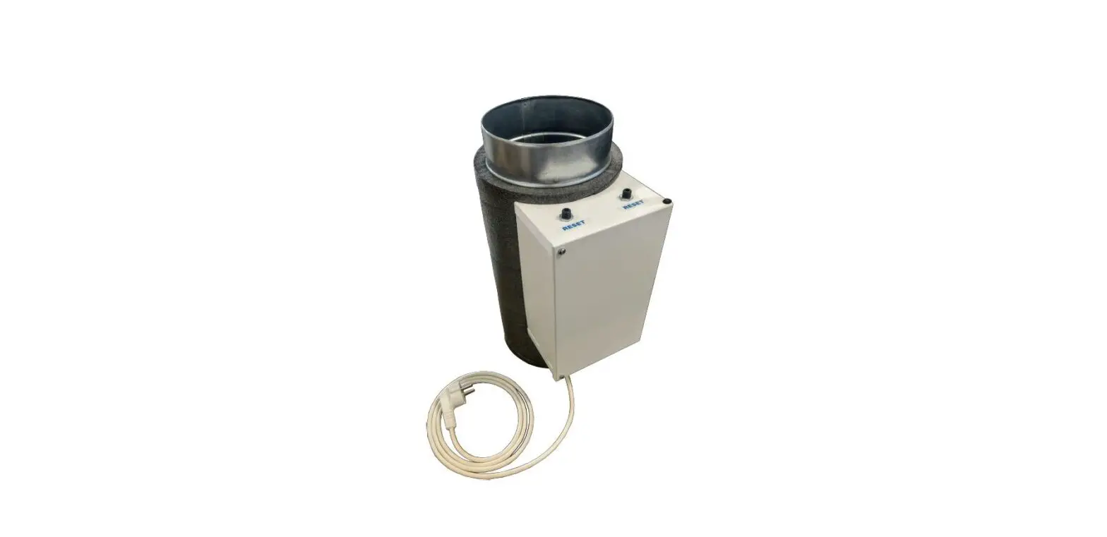
BRINK Flair 400 Electric Pre and Post Heater
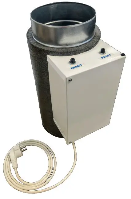
Flair post- and preheater
The Flair post heater and the Flair preheater are identical to each other and electrically connected to the Flair appliance in the same way.
Flair 200/225
- A = Ø160 mm with a reduction to DN125
- B = 350 mm
Flair 300/325
- A = Ø160
- B = 400 mm
Flair 400
- A = Ø180
- B = 400 mm
Flair 450/600
- A = Ø180 with enlargement to DN200
- B = 400 mm
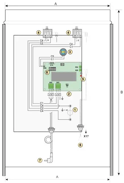
- C1 = Brown
- C2 = Bleu
- C3 = Green/yellow
- C4 = Black
- C5 = White
- Heating coil
- PCB type UVP1
- Temperature sensor
- Maximum safety with manual reset temperature sensor
- Red LED; lights up when the heater is connected to the Flair appliance
- 2-pole eBus connection X17 on Flair appliance
- Power plug 230V
- Dipswitch
By setting dipswitches on the PCB in the heater, the Flair appliance recognizes the connected heater. This Flair heater must always be mounted directly on the connection of the Flair appliance. After installation of the heater, the setting values of the Flair appliance must always be adjusted; for procedure adjustment settings Flair post-and preheater in the setting menu![]() of the Flair appliance, see the corresponding Flair installation instructions.
of the Flair appliance, see the corresponding Flair installation instructions.
Setting the correct dipswitch setting
At the factory the post- and preheater are supplied with all dipswitches set to “OFF”; the correct dipswitch setting must always be set by the installer.
Note: If the setting is incorrect, the heater will not function or will function incorrectly!
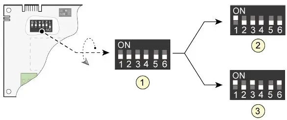
- Factory setting
- Dipswitch setting preheater
- Dipswitch setting post heater
Mounting position
Both the post- and preheater are always placed on the Flair appliance in the same way. The heating coil is always between the Flair appliance and the temperature sensor in the heater! The Flair post- and preheater can be mounted both horizontally and vertically. For horizontal mounting, always mount the connection box upwards for proper functioning of the temperature sensor!
Flair post heater
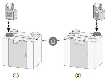
- Flair appliance left version
- Flair appliance right version
Flair preheater

- Flair appliance left version
- Flair appliance right version
Connection
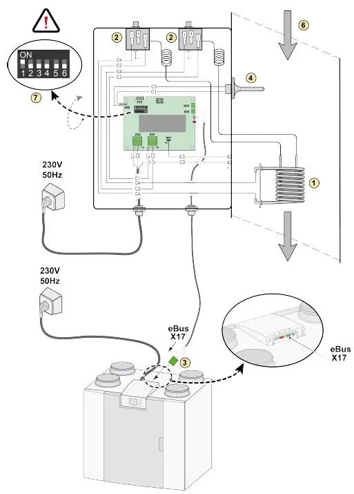
A Connection Flair post heater with Flair appliance
- Heating coil
- Maximum safety with manual reset
- 2-pole eBus connection X17 on Flair appliance
- Temperature sensor
- PCB type UVP1
- Airflow direction
- Dipswitch setting Flair post heater
- C1 = brown
- C2 = blue
- C3 = green/yellow
- C4 = black
- C5 = white
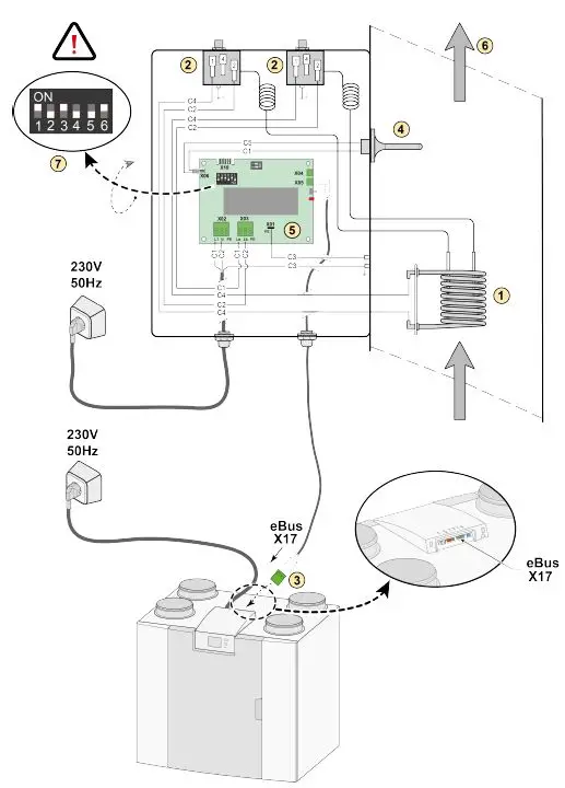
B Connecting Flair preheater with Flair appliance
- Heating coil
- Maximum safety with manual reset
- 2-pole eBus connection X17 on Flair appliance
- Temperature sensor
- PCB type UVP1
- Airflow direction
- Dipswitch setting Flair preheater
- C1 =brown
- C2 = blue
- C3 = green/yellow
- C4 = black
- C5 = white
Setting step number in Flair appliance
When a Flair post- and/or preheater is placed on a Flair appliance, this must always be set in the setting menu![]() of the Flair appliance!
of the Flair appliance!
For procedure adjustment settings in this set menu![]() of the Flair appliance, see the corresponding Flair installation instructions.
of the Flair appliance, see the corresponding Flair installation instructions.
When setting a preheater, set parameter 5.1 to ON; if a post heater is used, parameter 5.2 must be set to ON and, if required, the post heater temperature can still be set in parameter 5.3.
| Preheater | |||
| Step No. | Description | Factory setting | Adjusting range |
| 5.1 | Preheater ON and OFF | OFF | ON/ OFF |
| Postheater | |||
| Step No. | Description | Factory setting | Adjusting range |
| 5.2 | Postheater ON and OFF | OFF | ON/ OFF |
| 5.3 | Temperature postheater | 21 °C | 15,0 °C – 30,0 °C |
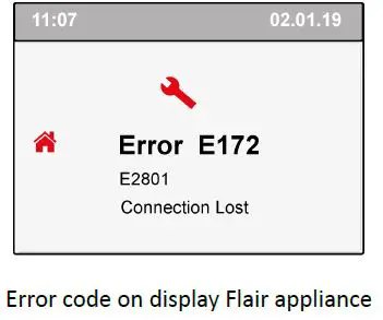
Fault
In the event of a fault in the Flair post-or preheater, a fault message will be visible on the display of the Flair appliance. A LED is mounted on the PCB of the Flair pre- and post-heater (for position LED see number 5 ® 1 Flair post-and preheater page 2). This LED flashes when the eBus connection has not yet been established. When the connection is established, the LED stops flashing. This startup can sometimes take a few minutes.
| Error codes preheater | |
| Error No. | Description |
| E171/ E2700 | General Error |
| E171/ E2701 | Preheater – connection lost |
| E171/ E2702 | Preheater – sensor error |
| E171/ E2703 | Preheater – element error |
| Error codes postheater | |
| Error No. | Description |
| E172/ E2800 | General Error |
| E172/ E2801 | Postheater – connection lost |
| E172/ E2802 | Postheater – sensor error |
| E172/ E2803 | Postheater – element error |
Technical information and service
| Technical information Flair post- and preheater | ||||
| Supply voltage | 230 V / 50 Hz | |||
| Rated current | 4,5 A | |||
| Rated power | 1000 W | |||
| Protection degree | IP20 | |||
| For use with | Flair 200/225 | Flair 300/325 | Flair 400 | Flair 450/600 |
| Heater art.no. | 310689 | 310690 | 310692 | 310699 |
| Duct diameter | Ø 125 mm | Ø 160 mm | Ø 180 mm | Ø 200 mm |
| Length heater | 350 mm | 400 mm | 400 mm | 400 mm |
| Total length | 540 mm | 400 mm | 400 mm | 530 mm |
| Total weight | 4,6 kg | 3,0 kg | 3,0 kg | 4,0 kg |
For more information see the Flair installation instructions.
Brink Climate Systems B.V.
P.O. Box 11, NL-7950AA Staphorst T: +31 (0) 522 46 99 44
E: [email protected].
W: www.brinkclimatesystems.nl.


