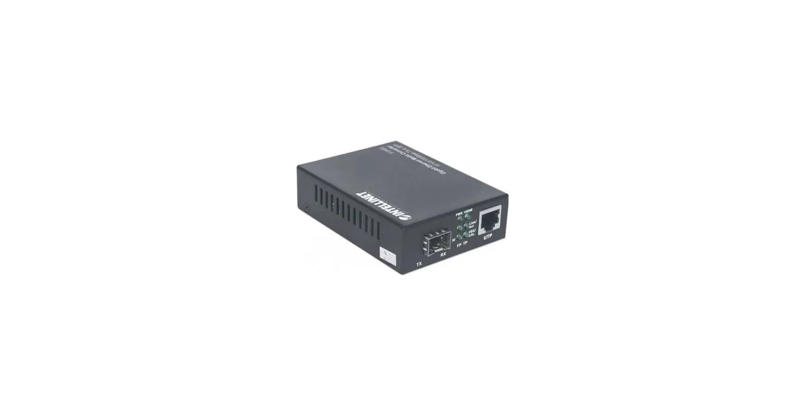
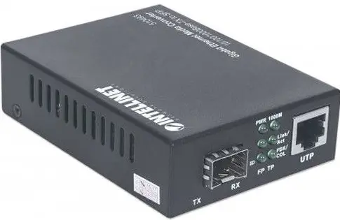
INTELLINET 508346 Industrial Gigabit Media Converter
Instructions
Features
- One 10/100/1000 RJ45 port supporting a maximum distance of 100 m (300 ft.)
- One 1000Base-LX fiber SC single-mode port supporting a maximum distance of 20 km (12.4 mi.)
- IP40 slim-type metal housing to withstand harsh industrial conditions
- Option for DIN-rail installation
- Two redundant DC inputs (12 – 58 V)
For specifications, visit intellinet-network.com. Register your product at register.intellinet-network.com/r/508346 or scan the QR code on the cover.
Connections
Twisted Pair – RJ45
Connect the UTP port of the media converter to an RJ45 port on the network (e.g., to an Ethernet switch). Cat5e or better cabling is recommended.
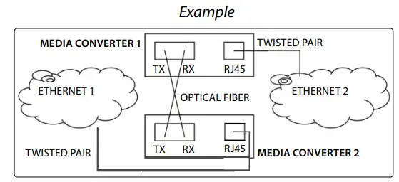
Fiber Optic
As shown, two fiber optic cables need to be connected between two ideally identical media converters. Make a connection from Media Converter 1 TX to Media Converter 2 RX, and from Media Converter 1 RX to Media Converter 2 TX. The maximum length and fiber cable specification depend on the model. (See Models.)
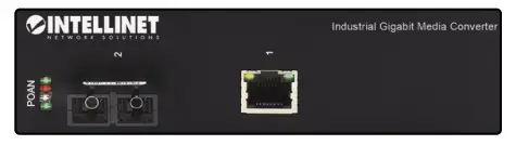
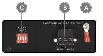
Front panel
| Item | LED | Color | Status | Description |
|
RJ45 Port | Port activity | Green | Flashing | Sending or receiving data. |
| On | Port is connected. | |||
| Off | Port is not connected. | |||
| Speed | Yellow | On | 1000 Mbps speed. | |
| Off | 10/100 Mbps speed. | |||
|
P — Power | Power and power-supply- under-voltage alarm (priority of under-voltage alarm is higher than power LED) |
Green | Flashing every 1s | Equipment power supply is lower than the lower limit of the input range of DC 12 V, indicating an under-voltage alarm. |
| On | Power channel is powered. | |||
| Off | Power channel is not powered. | |||
|
O — Optical Fiber Port | Fiber port and power supply overvoltage alarm (priority for overvoltage alarm is higher than fiber port Link/Act LED) |
Green | Flashing every 0.5s | The power supply of the device exceeds the upper limit of the input range of DC 58 V, indicating an overvoltage alarm. |
| On | Fiber port is connected. | |||
| Off | Fiber port is not connected. | |||
| Flashing | Sending or receiving data. | |||
|
A — Alarm | Device alarm and data transmission indicator |
Red | Flashing | Console/RS232/RS485 port is sending data (LED flashes to the rhythm of data being sent). |
| On | An issue has been detected (temperature, dying gasp, etc.). | |||
| Off | No alarm issue detected. | |||
|
N — NMC | Management indicator and data receiving |
Green | Flashing | Console/RS232/RS485 port is receiving data (LED flashes to the rhythm of data being received). |
| On | Module embedded and initialization is complete. | |||
| Off | No embedded module. |
Side Panel
Grounding
ATTENTION: When installing unit, connect the chassis ground first; when uninstalling the unit, disconnect the chassis ground last. Wire the grounding terminal to an earth grounding object to protect equipment from external electrical surges.
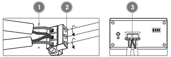
Terminal Block Installation
NOTE: Ensure all power is off/disconnected before beginning!
- loosen appropriate screws. Insert bare power-supply wires into appropriate terminal slots (positive wire into the positive slot; negative wire into the negative slot).
- Tighten appropriate screws to secure wires.
- Install the block into the device and tighten the screws.
DIP Switch
| Switch | Position | Description |
| 1-I/R Port Isolation | On | Enable port isolation |
| Off | Turn off port isolation | |
| 2-VLAN VLAN Isolation | On | Enable VLAN Isolation |
| Off | Turn off VLAN Isolation | |
| 3-Q/I QOS | On | Enable QOS function |
| Off | Turn off QOS function | |
| 4-F/P Flow Control | On | Enable flow control |
| Off | Turn off flow control |
Placement
Desktop Installation
Prior to use, place/position the device:
- on a level surface with at least 25 mm (approx. 1”) of clearance for ventilation;
- away from sources of electrical noise: radios, transmitters, broadband amplifiers;
- within 100 m (approx. 328’) of network devices it’s to be connected to.
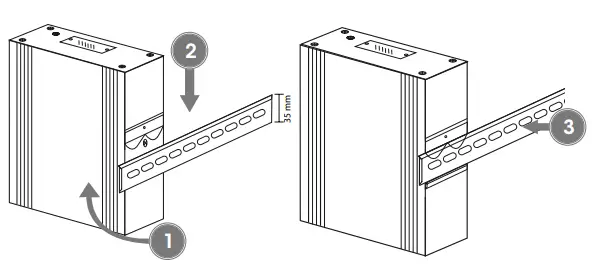
DIN-Rail Installation
- Angle spring of mounting clip over top lip of DIN rail.
- Push device down till clip clicks onto rail.
- Ensure installation is stable.
WASTE ELECTRICAL & ELECTRONIC EQUIPMENT
DISPOSAL OF ELECTRIC AND ELECTRONIC EQUIPMENT
(Applicable In The European Union And Other European Countries With Separate Collection Systems)
This symbol on the product or its packaging means that this product must not be treated as unsorted household waste. In accordance with EU Directive 2012/19/ EU on Waste Electrical and Electronic Equipment (WEEE), this electrical product must be disposed of in accordance with the user’s local regulations for electrical or electronic waste. Please dispose of this product by returning it to your local point of sale or recycling pickup point in your municipality.
WARRANTY AT
REGULATORY STATEMENTS
FCC Class B
This equipment has been tested and found to comply with the limits for a Class B digital device, pursuant to Part 15 of Federal Communications Commission (FCC) Rules. These limits are designed to provide reasonable protection against harmful interference in a residential installation. This equipment generates, uses and can radiate radio frequency energy, and if not installed and used in accordance with the instructions may cause harmful interference to radio communications. However, there is no guarantee that interference will not occur in a particular installation. If this equipment does cause harmful interference to radio or television reception, which can be determined by turning the equipment off and on, the user is encouraged to try to correct the interference by one or more of the following measures: reorient or relocate the receiving antenna; increase the separation between the equipment and the receiver; connect the equipment to an outlet on a circuit different from the receiver; or consult the dealer or an experienced radio/TV technician for help.
This device complies with the requirements of CE 2014/30/EU (UKCA Electromagnetic Compatibility Regulations 2016) and / or 2014/35/EU (UKCA Electrical Equipment [Safety] Regulations 2016). The Declaration of Conformity for is available at:
support.intellinet-network.com/barcode/508346
North America
IC Intracom America
550 Commerce Blvd.
Oldsmar, FL 34677, USA
All trademarks and trade names are the property of their respective owners intellinet-network.com
All trademarks and trade names are the property of their respective owners. IC Intracom. All rights reserved. Intellinet Network Solutions is a trademark of IC Intracom, registered in the U.S. and other countries.


