![]()
10G Base-T to 106 Base-R Media Converter
User’s Manual
Overview
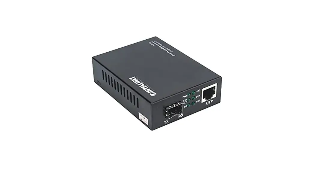
10G Base-T to 10G Base-R Media Converter supports two types media for network connection such as 10GBase-T and 10GBase-FX. The bridge media converter is designed with a 10Gbase Ethernet PHY chip that connects two types segments operation smoothly. This converter can be used as standalone unit or as slide-in module to the 19″ converter rack Chassis for use at a central wiring closet.
Technical Specifications
| Standards | 1000Base-T, 2.SGBase-T, SGbase-T, 10Gbase-T 1000Base-X, 2500Base-X, SGBase-R , 10GBase-R |
| Media Supported | 1000Base-T: Cats5 UTP/STP. MAX 100m; 2.5GBase-T: Cat5e UTP/STP. MAX 50m, 5GBase-T: Cat5e UTP/STP. MAX 50m; 10G Base-T: Cat6a UTP/STP. MAX 50m; |
| Port Type | RJ45, SFP Slot |
| Work Mode | 1000Base-T to 1000Base-X 2.5GBase-T to 2500Base-X 5Gbase-T to SGBase-R 10Gbase-T to 10GBase-R |
| Power Supply | 12V DC |
| Power consumption | MAX 5W |
| Operation Tempera tore | 0°C to 55°C |
| Relative Humidity | 5% to 80% (non-condensation) |
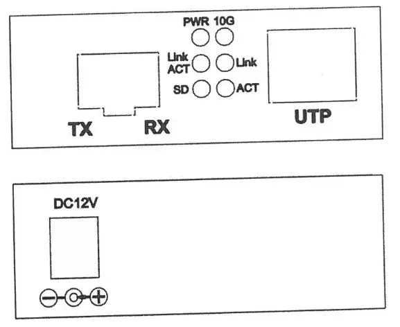
Fig. 3 Rear panel
Installing the Converter
For as a standalone unit:
- Verify the DC adapter conforms to your country DC power requirement and insert the power plug
- Connect the media cable for network connection
For as a slide-in unit:
- The slide-in Media Converter and Converter Rack Chassis should supplied only from the same source, both Media Converter Rack Chassis are built to match each other at dimension, DC jack, DC receptacle and power safety.
- Turn off the 19″ converter rack power
- Locate +12V DC power jack on converter back, carefully slide in and plug to 19″ rack +12V DC power receptacle
- Connect the media cable for network connection
- Turn on the converter rack power, the Power LED will light up
Wire connection, Front and Side panel
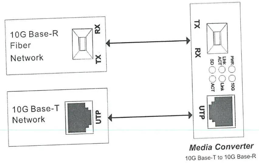
Fig: Basic Network connection
Check List
Before you start installing the Converter, verify that the package contains the following:
- The TP-Fiber Converter
- AC to 12V DC Power Adapter (for external models) or Power Cord (for internal models)
- The User’s Manual
Please notify your local sales distributor immediately if any of the aforementioned items is missing or damaged.
LED Description
| LED | Status | Description |
| PWR | On | Power is on and normal. |
| FX Link/Act | On | Connection status display for Fiber Link. “ON” indicates that Fiber link is in correct connection. |
| Blink | Active status display of fiber link. “Blink” indicates packet goes through FX end. | |
| SD | On | Fiber signal is detected. |
| 10G | On | Transfer rate of electric interface is 10Gbps. |
| Off | Rate of electric interface is 10Mbps. | |
| TX Link | On | Connection status display for electric link. “ON” indicates that electric link is in correct. |
| TX Act | Blink | Active Status display of fiber link “Blink” indicates packet goes through TX end. |


