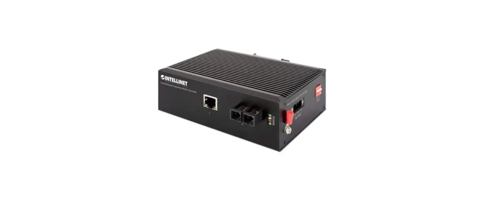
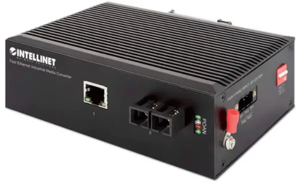
INTELLINET 508971 Industrial Gigabit Media Converter
For additional benefits
Scan to register your product warranty
or go to: register.intellinet-network.com/r/508971
Instructions
Media converters connect two Ethernet networks over a longer distance using fiber optic cable.
Features
- One 10/100/1000 RJ45 port supporting a maximum distance of 100 m (300 ft.)
- One SFP port for 1000Base-X optical transceiver modules and distances up to 120 km (75 mi.)
- IP40 slim-type metal housing to withstand harsh industrial conditions
- Option for DIN-rail installation
- Two redundant DC inputs (12 – 56 V) with terminal block For specifications, visit intellinetnetwork.com. Register your product at register.intellinet-network.com/r/508971 or scan the QR code on the cover.
Placement
Desktop Installation
Prior to use, place/position the device:
- on a level surface that can support the device with at least 25 mm (approx. 1”) of clearance for ventilation;
- away from sources of electrical noise: radios, transmitters, broadband amplifiers;
- within 100 m (approx. 328’) of network devices it’s to be connected to.
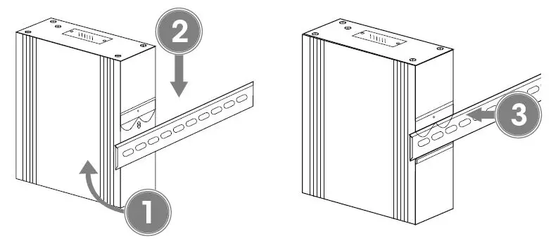
DIN-Rail Installation
- ngle spring of mounting clip over top lip of DIN rail.
- Push device down till clip clicks onto rail.
- Ensure installation is stable.

Connections
This product requires an SFP transceiver module that provides fiber optic connections.
- Insert the transceiver into the media converter and route the fiber optic cable into the transceiver.
- Route the other end of the fiber optic cable into a suitable port in your fiber optic network. Maximum length and fiber cable specification depend on the model.
RJ45
Connect the UTP port of the media converter to powered RJ45 device; e.g., to a network camera. Cat5e or better cabling is recommended.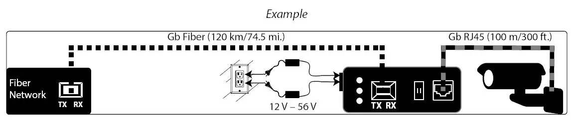
Power
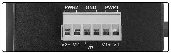
Terminal Block Installation
NOTE: Ensure all power is off/disconnected before beginning!
- Loosen appropriate screws. Insert bare power-supply wires into appropriate terminals (positive wire into positive [V1+] terminal, negative wire into negative [V1-] terminal, ground wire to ground [GND] terminal).
- Tighten appropriate screws to secure wires. Repeat these steps for a second power supply if desired (V2+, V2-, GND).
- Install block into the device.

Front panel
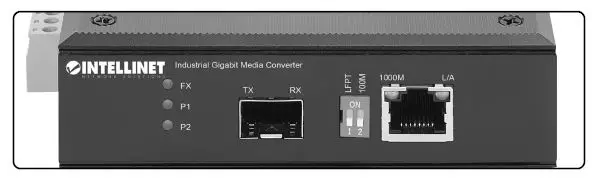
LEDs
| LED | Color | Status | Description |
| P1/P2 | Green | On | Power channel is powered. |
| Off | Power channel is not powered. | ||
| FX | Green | On | Fiber port is connected. |
| Off | Fiber port is not connected. | ||
| Flashing | Sending or receiving data. | ||
| 1000M | Yellow | On | 1000 Mbps speed |
| Off | 10/100 Mbps speed | ||
| L/A | Green | On | Valid port connection. |
| Off | Connection not established. | ||
| Flashing | Sending or receiving data. |
DIP Switch — LFPT/100M
| Switch | Position | Description |
|
LFPT | ON | Link Fault Pass Through enabled: Devices on a link must acknowledge that they are online before data can be transmitted. When one of the devices doesn’t respond, data cannot be sent. |
| OFF | Link Fault Pass Through disabled | |
| 100M | ON | Copper interface management — restricts data transfer rate to 100Mbps |
| OFF | No data transfer rate restriction |
North America
- IC Intracom America 550 Commerce Blvd. Oldsmar, FL 34677, USA
- All trademarks and trade names are the property of their respective owners. © IC Intracom. All rights reserved. Intellinet Network Solutions is a trademark of IC Intracom, registered in the U.S. and other countries.
- Printed on recycled paper.


