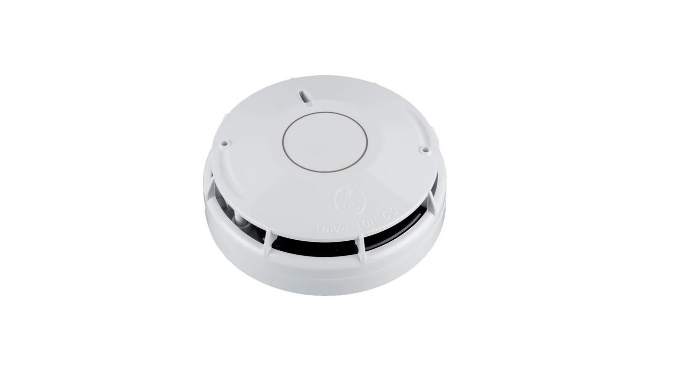
apollo XP95A and Soteria UL 268 7th Edition Detectors Instruction Manual
General
These instructions apply to the Apollo Soteria UL Bases. Please refer to the table below for instructions on how to install:
| Applicable Wiring Diagram (page 3) | Applicable Products |
| Fig. 1 – New Installs (supports isolation) | SA5000-210 – Soteria UL Base – 4” SA5000-230 – Soteria UL Base – 6” |
| Fig. 2 – Retrofits or Isolator bypassed with a Remote LED | SA5000-210 – Soteria UL Base – 4” SA5000-230 – Soteria UL Base – 6” |
| Fig. 3 – Retrofits or Isolator bypassed with a Common Remote LED | SA5000-210 – Soteria UL Base – 4” SA5000-230 – Soteria UL Base – 6” |
Installation
These products must be installed in accordance with the applicable NFPA standards, local codes and jurisdictional authorities. Failure to follow these instructions may result in failure of the detectors to report an alarm condition. Apollo Fire Detectors Limited is not responsible for detectors which are improperly installed, maintained or tested.
Before installing these products, check the continuity, polarity and insulation resistance of all wiring. Check that installation is in accordance with the fi re system drawings and conforms to all applicable local codes such as NFPA 72.
Use 3″ octagonal box for direct connection to the base. 4″ octagonal and 4″ square boxes may be used with compatible UL listed mounting brackets. When mounting on a wall, install 4″ to 12″ from the ceiling. Secure the base to the electrical box with appropriate screws.
Do not overtighten the screws. For information on how to set the address of each device correctly refer to the section ‘XPERT 8 Card Addressing’ overleaf.
If you are using shielded cable, please follow the instructions below:
- Connect the shield to the terminal on the base.
- When shielded loop cable is used, connection of the shield, also known as the functional earth (FE), must be terminated in accordance with the control panel manufacturer’s recommendations and local codes.
- Unless instructed otherwise, ensure that all segments of the loop cable has functional earth (FE) continuity and take care that it is isolated from building earth (also known as protective earth (PE)) points such as metalwork, cable trays or junction boxes.
PLEASE NOTE:
Smoke detectors are NOT to be used with detector guards.
During construction work it is essential that the detector has it’s dust cover fi tted. The build-up of dust inside a detector can lead to a trouble signal or false alarm.
Installation Diagram
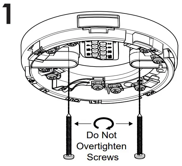
 Screws not provided
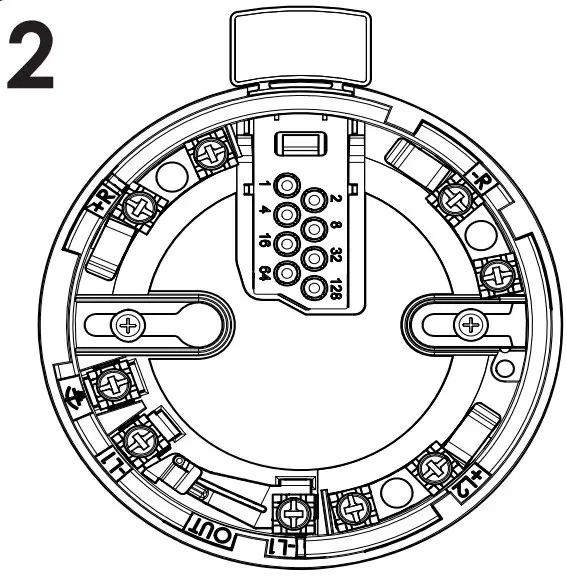
For wiring, please see Fig 1, 2 & 3 i
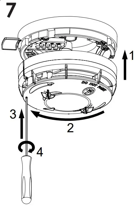
1.5mm A/F Hex Grub Screw for use as anti-tamper / locking mechanism
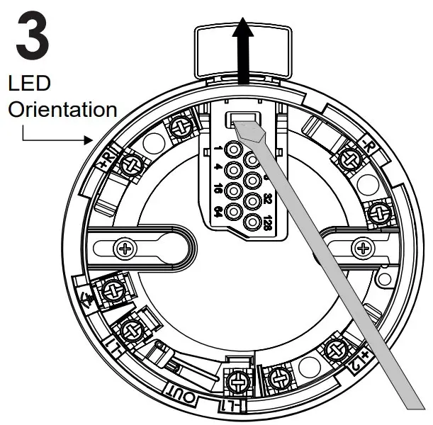
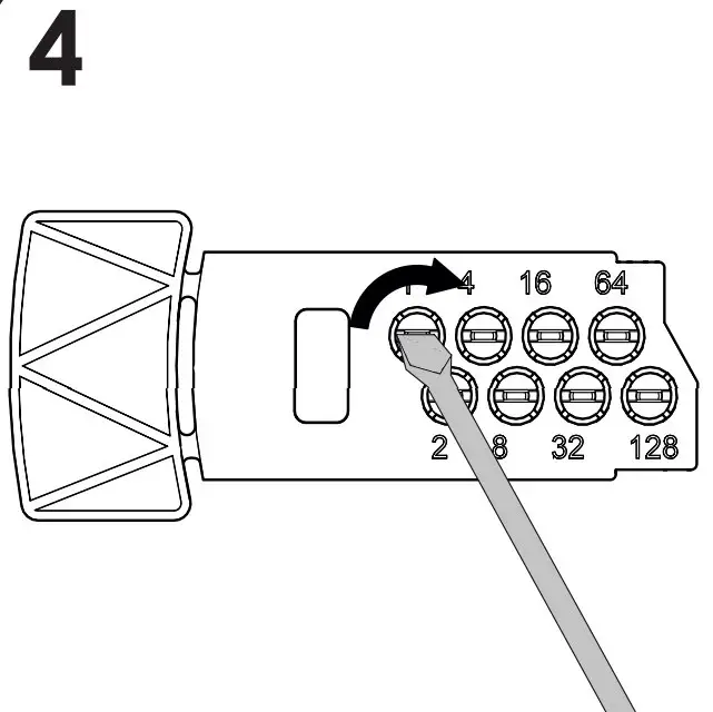
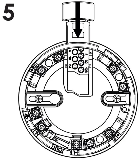
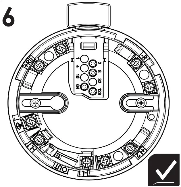
XPERT 8 Card Addressing
Select the desired address and remove the pips indicated in black.
To reach maximum address range use Soteria UL Bases with XPERT 8 card, Soteria Detector and Core Protocol Control Panel.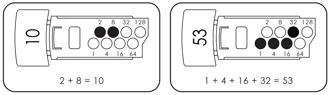
Further details of XPERT 8 addressing can be found in the Apollo Fire App, please refer to https://www.apollo-fire. co.uk/training-support/apollo-mobile-app
For further technical information please refer to Technical Bulletin 39215-400 Issue 1.
Wiring
CAUTION: Do not use looped wire under wiring terminals. Break wire run to provide supervision of connections. Terminals L1 and L2 are polarity sensitive. It is recommended the wiring be no smaller than 18AWG (0.8mm2). Wire sizes up to 14 AWG (3.3mm2) may be used.
Warning: Check the base compatibility before installing Check the polarity for Soteria UL detector installation
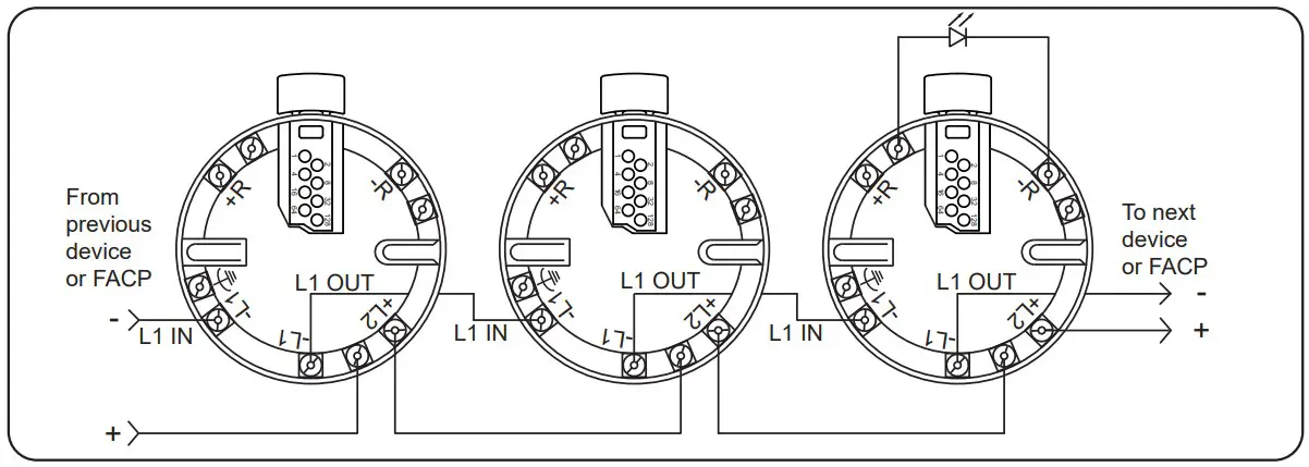
Fig. 1 Schematic Wiring Diagram: Soteria UL Base wiring with remote LED connection. To be used with new installs for XP95A and Soteria UL detectors
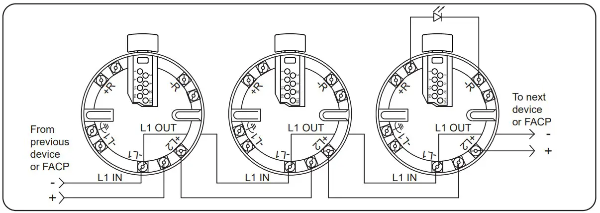
Fig. 2 Schematic Wiring Diagram: Soteria UL Base Detector to bypass isolator with remote LED connection. To be used in a retrofi t application for the older version of XP95A or Discovery UL product. Can also be used when the isolator feature is not required
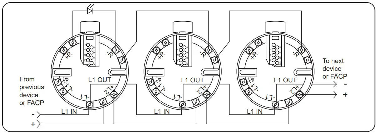
Fig. 3 Schematic Wiring Diagram: Soteria UL Base to bypass isolator with a Common Remote LED. To be used in a retrofi t application for the older version of XP95A or Discovery UL product. Can also be used when the isolator feature is not required
Technical Data
Technical Data XP95A Detectors
| Detector Model No | SA5050-250APO | SA5050-350APO | SA5500-450APO |
| Detector Type | XP95A Smoke Detector | XP95A Multi-Criteria Detector (Smoke/Heat) | XP95A Heat Detector |
| Equivalent Obsolete Dectector | 55000-650 | 55000-886 | 55000-450 |
| UL Listed Voltage | 17 – 28 V dc | 17 – 28 V dc | 17 – 28 V dc |
| Modulation Voltage (V peak to peak) | 5 – 9 V | 5 – 9 V | 5 – 9 V |
| Maximum Alarm Current LED on* | 4 mA | 4 mA | 2.5 mA |
| Surge Current* | 1 mA | 1 mA | 1 mA |
| Supervisory Current* | 340 μA | 500 μA | 250 μA |
| Additional Remote LED Current* | 5 mA | 5 mA | 5 mA |
| Heat Element Rating | N/A | Rate of Rise (RoR) 20ºF/min (11ºC/min) | 131ºF (55ºC) |
| Sensitivity | UL 1.23%/Ft -2.09%/Ft ULC 1.44%- 2.3%/Ft | UL 1.23%/Ft -2.09%/Ft ULC 1.44%- 2.3%/Ft | N/A |
| UL/ULC Instruction | Smoke-automatic fire detec- tor for use with a S5022 UL/ ULC listed base | Smoke-automatic fire detector head with integral heat detector for use with a S5022 UL/ULC listed base | Heat-automatic fire detector for use with a S5022 UL/ULC listed base |
| Test Method | Please refer to the panel manufacturer instructions Spray with any of the following smoke products:
| Hair Dryer | |
| Control Panel | Refer to www.apollo-fire.co.uk for compatible panels | ||
Technical Data Soteria UL Detectors
| Detector Model No | SA5150-650APO** | SA5150-750APO** | SA5800-450APO |
| Detector Type | Soteria UL Smoke Detector | Soteria UL Multi-Criteria Detector (Smoke/Heat) | Discovery/Soteria UL Non-isolating Heat Detector |
| Equivalent Obsolete Dectector | 58000-650 | 58000-750 | 58000-450 |
| UL Listed Voltage | 17- 28 V dc | 17 – 28 V dc | 17- 28 V dc |
| Modulation Voltage (V peak to peak) | 5 – 9 V | 5 – 9 V | 5 – 9 V |
| Maximum Alarm Current LED on* | 4 mA | 4 mA | 3.5 mA |
| Surge Current* | 1 mA | 1 mA | 1 mA |
| Supervisory Current* | 500 μA | 500 μA | 500 μA |
| Additional Remote LED Current* | 5 mA | 5 mA | 5 mA |
| Heat Element Rating | N/A | Modes 1,3,4 Rate of Rise (RoR) 20ºF/min (11ºC/min). Mode 5 135ºF (57ºC) | 135ºF (57ºC) – 210ºF (99ºC) |
| Sensitivity | As SA5050-250APO | As SA5050-350APO | N/A |
| UL/ULC Instruction | Smoke-automatic fire detec- tor for use with a S5022 UL/ ULC listed base | Smoke-automatic fire detector head with integral heat detector for use with a S5022 UL/ULC listed base | Heat-automatic fire detector for use with a S5022 UL/ULC listed base |
| Test Method | Please refer to test methods in the table above | ||
| Control Panel | Refer to www.apollo-fire.co.uk for compatible panels | ||
* All current measurements made with polling off
**Isolation feature is only available in SA5150-650APO and SA5150-750APO
© Apollo Fire Detectors Ltd 2021
Apollo Fire Detectors Ltd,
36 Brookside Road, Havant, Hampshire, PO9 1JR, UK
Tel +44 (0)23 9249 2412 e-mail: [email protected]
Website: www.apollo-fire.co.uk
In the USA: Apollo America Inc.,
30 Corporate Drive, Auburn Hills, Michigan, 48326, USA
Tel: (248) 332-3900 Fax: (248) 692-0888
e-mail: [email protected]
Website: www.apollo-fire.com