![]() PAD300-4DB/6DB
PAD300-4DB/6DB
4”/6” Detector Base
![]()
Features
- Terminals marked with polarity to assist with installation
- Duplicate Terminals for In-and-out SLC Wiring
- Terminals accept 22 to 12 AWG wire sizes
- Installs on Single Gang, Double Gang, Octagon or 4” Square Box
- Locking tab prevents unauthorized detector removal
- Product includes 5-year warranty
- 6” mounting base comes with trim plate cover
Application
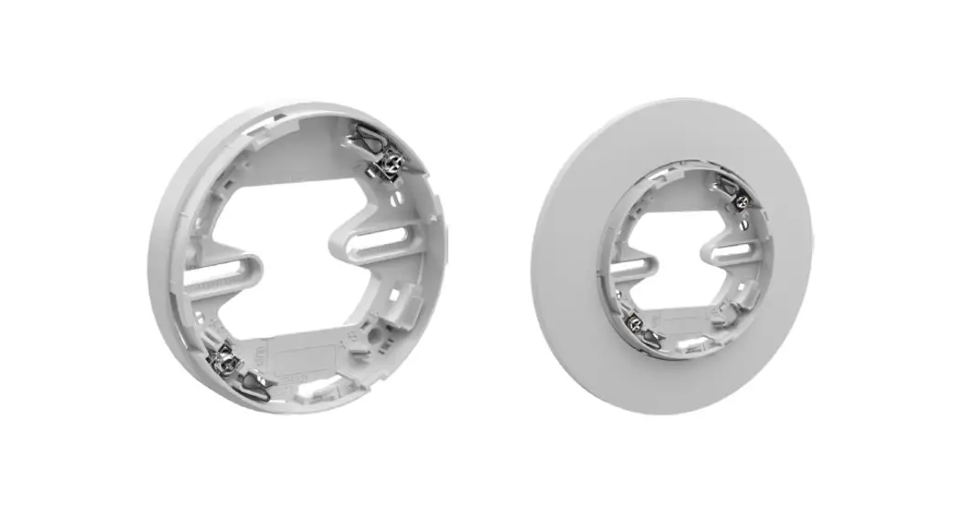
The Potter PAD300-6DB and PAD300-4DB detector bases are used to install PAD300 series detectors. The PAD300-6DB will mount on a single gang, double gang, octagon, 4” square, 50mm, 60mm, and 70mm electrical box.
Description
The PAD300-6DB and PAD300-4DB are low-profile, surface-mount bases used with Potter’s addressable detectors. The base uses screw clamp terminals that accept wire ranging from 22 to 12 AWG. When installed on recessed electrical boxes, the PAD300-6DB is wide enough to completely cover the back box and the immediate surrounding area. The base is equipped with a locking tab to deter unauthorized removal of the attached detector.
Technical Specifications
| Installation Temp Range | 32°F to 150°F (0°C to 66°C) |
| Operating Humidity Range | 0% to 93% (Non-condensing) |
| Dimension | PAD300-4DB: 3.93 in / 100 mm PAD300-6DB: 6.3 in / 160 mm |
| Weight | PAD300-4DB: 1.34 oz / 38 g PAD300-6DB: 3.03 oz / 86 g |
| Height | 0.76 in / 20 mm |
| Acceptable Wire Gauge | 22 to 12AWG |
| Mounting Options | • Single Gang • Double Gang • 3-1/2″ Octagon Box • 4″ Octagon Box • 4″ Square with Plaster Ring • 50mm c/c Box • 60mm c/c Box • 70mm c/c Box |
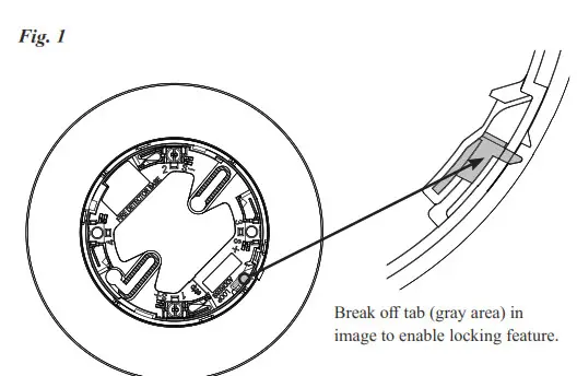
Locking Feature
The PAD300-6DB and PAD300-4DB include a locking feature that prevents removal of the detector without using a tool.
- To enable this feature, break off the locking tab (See Figure 1), and then install the detector.

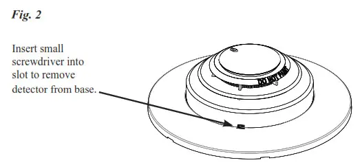
- To remove the detector from the base when the locking feature has been enabled, insert a small screwdriver into the slot on the base to push the plastic tab while simultaneously turning the detector head counter-clockwise.

Ordering Information
| Model | Description | Stock No. |
| PAD300-4DB | 4” Detector Base | 3992781 |
| PAD300-6DB | 6” Detector Base | 3992782 |
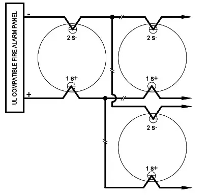
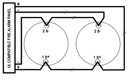
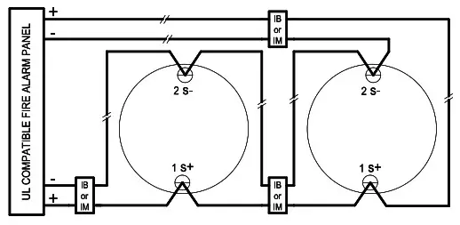
Wiring Diagrams
Fig. 3
- Class B Wiring:

- Class A Wiring:

- Class X Wiring:

![]() Potter Electric Signal Company, LLC
Potter Electric Signal Company, LLC
St. Louis, MO
Phone: 800-325-3936
www.pottersignal.com
PRINTED IN USA
8830203- REV A
10/22


