![]()
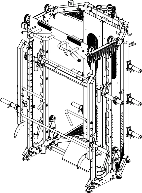
 ASSEMBLY MANUAL
!! IMPORTANT !!
DO NOT FULLY TIGHTEN HARDWARE UNTIL COMPLETELY ASSEMBLED.
PLEASE NOTE: Some components may be pre-assembled.
YOU MUST FOLLOW THESE PRECAUTIONS TO AVOID INJURY. SERIOUS INJURY CAN OCCUR ON THIS EQUIPMENT.
- Before using, read all the warnings and precautionary instructions for the use of this machine. Use only for exercise intended. DO NOT modify this machine.
- Consult a physician prior to use.
- Keep clothing and body parts free from all moving parts.
- Fully inspect machine before use. DO NOT use if broken or damage. DO NOT attempt to repair. Notify professional immediately.
- Be certain that all securing and safety pins are completely inserted and tightened during use. Use only the pins provided by the manufacturer. If unsure seek assistance.
- Inspect all parts of the machine including cables and pulleys for wear and or damage prior to use. DO NOT attempt to fix, seek professional assistance.
- Children are not allowed near this machine. Teenagers need to be supervised.
- This machine must be used and stored indoors in a dry and dust free environment. Not to be used or stored outside, on a veranda, in an unlined shed or any other type of shelter.
- IMPORTANT! When removing crown release pin (42) to fold machine, always hold the crown to avoid it from dropping onto the user.
As we are continually evolving our products please note that some miner details in the manual may differ from the product received.
PARTS LIST
No. | Description | Notes | Qty |
1 | Lower connection frame | – | 1 |
2 | Upper connection frame | – | 1 |
3 | Upright frame right | – | 1 |
4 | Hexagon bolt | M10*75 | 48 |
5 | Lock nut | M10 | 84 |
6 | Flat washer | Ø10 | 154 |
7 | Upright frame left | – | 1 |
8 | Upper side connection frame right | – | 1 |
9 | Upper side connection frame left | – | 2 |
10 | Side connecting frame right | – | 1 |
11 | Front connecting frame right | – | 2 |
12 | Inner shaft | Ø20*85 | 5 |
13 | Hexagon Bolt | M10*20 (thin head) | 8 |
14 | Large flat washer | Ø30*Ø10*3 | 21 |
15 | Lifting bolt | M10 | 2 |
16 | Side connecting frame left | – | 1 |
17 | Upper side connection frame left | – | 1 |
18 | Bottom plate | T5 | 4 |
19 | Upright post | 50*50*2 | 2 |
20 | Stainless steel front post right | 50*50*1.5 | 1 |
21 | Upper frame plate | T5 | 2 |
22 | Fixed plate | T5 | 2 |
23 | Smith machine holder | – | 1 |
24 | Pulley slider right | – | 1 |
25 | Pulley slider left | – | 1 |
26 | Hexagon bolt | M10*70 | 14 |
27 | Hexagon bolt | M10*25 | 5 |
28 | Upper decorative plate | T2 | 2 |
29 | Jammer foot plate fixing bracket right | T4 | 1 |
30 | Hexagon bolt | M10*80 | 6 |
31 | Jammer foot plate fixing bracket left | T4 | 1 |
32 | Stainless steel front post left | 50*50*1.5 | 1 |
33 | Smith machine racking plate | T5 | 2 |
34 | Guide rod holder | – | 2 |
35 | Inner shaft | Ø12*59.5 | 4 |
36 | Quick release locking foot | – | 2 |
37 | Front crown | – | 1 |
38 | Crown fixed plate right | – | 1 |
39 | Crown fixed plate left | – | 1 |
40 | Hexagon bolt | M8*16 | 20 |
41 | Flat washer | Ø8 | 28 |
42 | Crown release pin | Ø12*110 | 1 |
43 | Weight stack rubber pad | Ø60*Ø27*42 | 4 |
44 | Weight stack | 100kg | 2 |
45 | Stainless steel guide rod | – | 4 |
46 | Selector rod | Ø25 | 2 |
47 | Cylindrical pin | 10*60 | 2 |
48 | Magnetic pull pin | 10*100 | 2 |
49 | Weight stack pulley | – | 2 |
50 | Hexagon bolt | M10*95 | 4 |
51 | Long smith machine guide rod | Ø25*1850 | 2 |
52 | Safety hook left | – | 1 |
53 | Sliding tube left | – | 1 |
54 | Smith machine bar | – | 1 |
55 | Smith machine bar sleeve | – | 2 |
56 | Sliding tube right | – | 1 |
57 | Safety hook right | – | 1 |
58 | Long smith machine guide rod rubber pad lower | Ø60*Ø26*45 | 2 |
59 | Long smith machine guide rod rubber pad upper | Ø60*Ø26*45 | 2 |
60 | Adjustable setting lever | M12*32 | 1 |
61 | Aluminium cover | Ø50*Ø19*Ø11 | 3 |
62 | Fixing sleeve | Ø45*Ø25.5*Ø35 | 2 |
63 | Grub screw | M8*10 | 2 |
64 | Button head socket screw | M12*40 | 2 |
65 | Spring washer | Ø12 | 2 |
66 | Flat washer | Ø12 | 2 |
67 | Button head bolt | M10*20 | 3 |
68 | Spring washer | Ø10 | 3 |
69 | Snap lock collar | Ø80*Ø50*49 | 2 |
70 | Pulley | Ø92 | 8 |
71 | Hexagon bolt | M10*45 | 12 |
72 | Floating pulley bracket | – | 2 |
73 | Pulley | Ø50 | 4 |
74 | Sleeve | Ø20*16*10.5*20.5 | 8 |
75 | Cable | Ø5*4095 bulb | 2 |
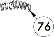
76 | Carabena | – | 10 |
78 | Pulley | Ø75 | 4 |
79 | Cable | – | 2 |
80 | Weight plate storage | – | 6 |
81 | Spring collar | Ø50 | 8 |
82 | Shield right | – | 1 |
83 | Hexagon bolt | M6*16 | 10 |
84 | Flat washer | Ø6 | 10 |
85 | Shield rubber seal | 32*1956 | 1 |
86 | Upper left/lower right triangle trim board | – | 2 |
87 | Hexagon bolt | M8*20 | 8 |
88 | Upper right/lower left triangle trim board | – | 2 |
89 | Shield left | – | 1 |
90 | Storage hook | – | 10 |
91 | J hook right | – | 1 |
92 | J hook left | – | 1 |
93 | Safety arm right | – | 1 |
94 | Safety arm left | – | 1 |
95 | Foam roller anchoring system | – | 1 |
96 | Dipping handle left | – | 1 |
97 | Dipping handle right | – | 1 |
98 | Core trainer | – | 1 |
99 | Sleeve | Ø33*Ø29*Ø20*18 | 2 |
100 | Leg press plate | – | 1 |
101 | T-shape locking pin | Ø10*85 | 6 |
102 | Jammer arm foot plate | – | 1 |
103 | Jammer arm fixing bracket right | – | 1 |
104 | Jammer arm right | – | 1 |
105 | Jammer handle | – | 2 |
106 | Jammer arm stopper bracket right | – | 1 |
107 | Jammer arm front rod | – | 1 |
108 | Jammer arm fixing bracket left | – | 1 |
109 | Jammer arm left | – | 1 |
110 | Lat pull down bar | – | 1 |
111 | Short tri-bi bar | – | 1 |
112 | D handle | – | 2 |
113 | Chain and Carabena | – | 2 |
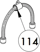
114 | Tricep/bicep rope | – | 1 |
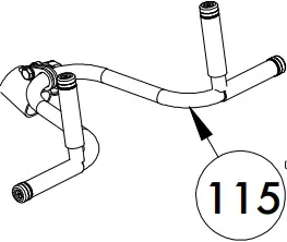
115 | Barbell lifting device | Ø28*690 | 1 |
120 | Jammer arm stopper bracket left | – | 1 |
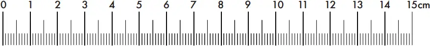
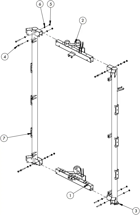
ASSEMBLY STEP 1
No. | Description | Notes | Qty |
1 | Lower connection frame | – | 1 |
2 | Upper connection frame | – | 1 |
3 | Upright frame right | – | 1 |
4 | Hexagon bolt | M10*75 | 8 |
5 | Lock nut | M10 | 8 |
6 | Flat washer | Ø10 | 16 |
7 | Upright frame left | – | 1 |
ASSEMBLY STEP 1 INSTRUCTIONS
- Connect lower connection frame (1) with upright frame right (3) and upright frame left (7) with M10*75 hexagon bolt (4), Ø10 flat washer (6), M10 lock nut (5).
- Connect upper connection frame (2) with upright frame right (3) and upright frame left (7) with M10*75 hexagon bolt (4), Ø10 flat washer (6), M10 lock nut (5).
ASSEMBLY STEP 2
No. | Description | Notes | Qty |
4 | Hexagon bolt | M10*75 | 8 |
5 | Lock nut | M10 | 8 |
6 | Flat washer | Ø10 | 16 |
8 | Upper side connection frame right | – | 1 |
9 | Upper side connection frame left | – | 2 |
10 | Side connecting frame right | – | 1 |
11 | Front connecting frame right | – | 2 |
12 | Inner shaft | Ø20*85 | 4 |
13 | Hexagon Bolt | M10*20 (thin head) | 6 |
14 | Large flat washer | Ø30*Ø10*3 | 8 |
15 | Lifting bolt | M10 | 2 |
16 | Side connecting frame left | – | 1 |
17 | Upper side connection frame left | – | 1 |
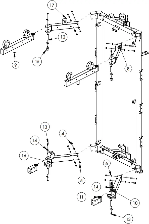
ASSEMBLY STEP 2 INSTRUCTIONS
- Connect side connecting frame right (10) with side connecting frame (16) and front connecting frame right (11) with hexagon bolt (13), large flat washer (14), inner shaft (12).
- Assemble the side connecting frame right (10) and side connecting frame left (16) to upper frame right (3) and upper frame left (7) with M10*75 hexagon bolt (4), flat washer (6), lock nut (5).
- Connect upper side connection frame right (8) and upper side connection frame left (17) to upper frame right (3) and upper frame left (7) with M10*75 hexagon bolt (4), flat washer (6), lock nut (5).
- Assemble upper side connection frame left (9) to upper side connection frame left (17) with M10*20 hexagon bolt (13), Ø30*Ø10*3 large flat washer (14), Ø20*85 inner shaft (12), lifting bolt (15). Assemble upper side connection frame left (9) to upper side connection frame right (8) with M10*20 hexagon bolt (13), Ø30*Ø10*3 large flat washer (14), Ø20*85 inner shaft (12), lifting bolt (15)
ASSEMBLY STEP 3
NOTE: (27) only goes through one plate (18) to secure smith machine holder (23).
No. | Description | Notes | Qty |
4 | Hexagon bolt | M10*75 | 18 |
5 | Lock nut | M10 | 30 |
6 | Flat washer | Ø10 | 60 |
18 | Bottom plate | T5 | 4 |
19 | Upright post | 50*50*2 | 2 |
20 | Stainless steel front post right | 50*50*1.5 | 1 |
21 | Upper frame plate | T5 | 2 |
22 | Fixed plate | T5 | 2 |
23 | Smith machine holder | – | 1 |
24 | Pulley slider right | – | 1 |
25 | Pulley slider left | – | 1 |
26 | Hexagon bolt | M10*70 | 4 |
27 | Hexagon bolt | M10*25 | 2 |
28 | Upper decorative plate | T2 | 2 |
29 | Jammer foot plate fixing bracket right | T4 | 1 |
30 | Hexagon bolt | M10*80 | 6 |
31 | Jammer foot plate fixing bracket left | T4 | 1 |
32 | Stainless steel front post left | 50*50*1.5 | 1 |
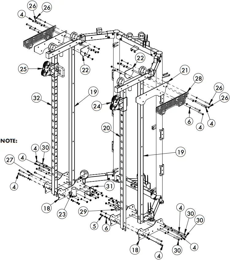
ASSEMBLY STEP 3 INSTRUCTIONS
- Fix smith machine holder (23) to the bottom frame plate (18) with M10*25 hexagon bolt (27), Ø10 flat washer (6), and M10 lock nut (5). NOTE: M10*25 hexagon bolt (27) only goes through one bottom frame plate (18).
- Fix the bottom frame plate (18), jammer foot plate fixing bracket right (29) and the jammer foot plate fixing bracket left (31) to the main frame with M10*80 hexagon bolt (30), Ø10 flat washer (6), and M10 lock nut (5).
- Install the pulley slider right (24) and pulley slider left (25) on the right (20) and left (32) stainless steel front posts.
- Install upright post (19), stainless steel front post right (20) and left (32) in middle of bottom frame plate (18) with M10*75 hexagon bolt (4), Ø10 flat washer (6), M10 lock nut (5).
- Install upper frame plate (21), fixing plate (22) and upper decorative plate (28) on the outside of upper side connection frame left (9).
ASSEMBLY STEP 4
No. | Description | Notes | Qty |
4 | Hexagon bolt | M10*75 | 10 |
5 | Lock nut | M10 | 20 |
6 | Flat washer | Ø10 | 30 |
12 | Inner shaft | Ø20*85 | 1 |
13 | Hexagon Bolt | M10*20 (thin head) | 2 |
14 | Large flat washer | Ø30*Ø10*3 | 12 |
26 | Hexagon bolt | M10*70 | 10 |
33 | Smith machine racking plate | T5 | 2 |
34 | Guide rod holder | – | 2 |
35 | Inner shaft | Ø12*59.5 | 4 |
36 | Quick release locking foot | – | 2 |
37 | Front crown | – | 1 |
38 | Crown fixed plate right | – | 1 |
39 | Crown fixed plate left | – | 1 |
40 | Hexagon bolt | M8*16 | 8 |
41 | Flat washer | Ø8 | 8 |
42 | Crown release pin | Ø12*110 | 1 |
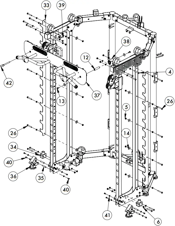
ASSEMBLY STEP 4 INSTRUCTIONS
- Quick release lock foot (36) is installed on the main frame with M8*16 hexagon bolt (40), Ø8 flat washer (41), Ø12*59.5 inner shaft (35).
- Use M10*75 hexagon bolt (4), Ø10 flat washer (6), M10 lock nut (5) to fix guide rod holder (34) to main frame.
- Assemble the crown fixed plate right (38), crown fixed plate left (39) with M10*20 hexagon bolt (4), Ø10 flat washer (6), M10 lock nut (5) to main frame.
- Front crown (37) is fixed with M10*20 hexagon bolt (13), Ø10 large flat washer (14), Ø20*85 inner shaft (12) is installed on the crown fixed plate right (38) and fixed to crown fixed plate left (39) with Ø12*110 crown release pin (42).
- Use M10*70 hexagon bolt (26), flat washer (6), M10 locking nut (5), large flat washer (14) to fix smith machine racking plate (33) to main frame.
ASSEMBLY STEP 5
No. | Description | Notes | Qty |
6 | Flat washer | Ø10 | 4 |
43 | Weight stack rubber pad | Ø60*Ø27*42 | 4 |
44 | Weight stack | 100kg | 2 |
45 | Stainless steel guide rod | – | 4 |
46 | Selector rod | Ø25 | 2 |
47 | Cylindrical pin | 10*60 | 2 |
48 | Magnetic pull pin | 10*100 | 2 |
49 | Weight stack pulley | – | 2 |
50 | Hexagon bolt | M10*95 | 4 |
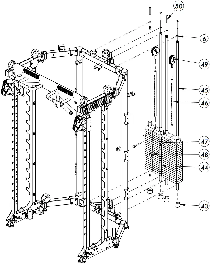
ASSEMBLY STEP 5 INSTRUCTIONS
- Assemble the stainless steel guide rod (45) through the weight stack rubber pad (43), weight stack (44) and fix to the main frame with M10*95 hexagon bolt (50) and Ø10 flat washer (6).
- Install selector rod (46) on weight stack (44) with cylindrical pin (47).
- Install the weight stack pulley (49) on the selector rod (46).
- Put magnetic pull pin (48) into weight stack (44).
ASSEMBLY STEP 6
No. | Description | Notes | Qty |
51 | Long smith machine guide rod | Ø25*1850 | 2 |
52 | Safety hook left | – | 1 |
53 | Sliding tube left | – | 1 |
54 | Smith machine bar | – | 1 |
55 | Smith machine bar sleeve | – | 2 |
56 | Sliding tube right | – | 1 |
57 | Safety hook right | – | 1 |
58 | Long smith machine guide rod rubber pad lower | Ø60*Ø26*45 | 2 |
59 | Long smith machine guide rod rubber pad upper | Ø60*Ø26*45 | 2 |
60 | Adjustable setting lever | M12*32 | 1 |
61 | Aluminium cover | Ø50*Ø19*Ø11 | 1 |
62 | Fixing sleeve | Ø45*Ø25.5*Ø35 | 2 |
63 | Grub screw | M8*10 | 2 |
64 | Button head socket screw | M12*40 | 2 |
65 | Spring washer | Ø12 | 2 |
66 | Flat washer | Ø12 | 2 |
67 | Button head bolt | M10*20 | 1 |
68 | Spring washer | Ø10 | 1 |
69 | Snap lock collar | Ø80*Ø50*49 | 2 |
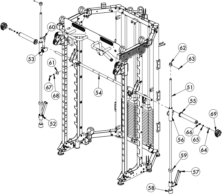
ASSEMBLY STEP 6 INSTRUCTIONS
- Pass the long smith machine guide rod (51) through the long smith machine guide rod rubber pad lower (58), safety hook left (52), long smith machine guide rod rubber pad upper (59), sliding tube left (53) and fix to left frame with fixing sleeve (62) and M8*10 grub screw (63).
- Connect smith machine bar (54) through sliding tube left (53) with M10*20 hexagon bolt (67), Ø10 spring washer (68), Ø50*Ø19*Ø11 aluminium cover (61).
- Pass the long guide rod (51) through the long smith machine guide rod rubber pad lower (58), safety hook right (57), long smith machine guide rod rubber pad upper (59), sliding tube right (56) and fix to left frame with fixing sleeve (62) and M8*10 grub screw (63).
- Use M12*45 button head socket screw (64), Ø12 flat washer (66) and Ø12 spring washer (65) to cover the smith machine bar sleeve (55) to mount on the smith machine (54).
- Install the snap lock collars (69) on the smith machine bar sleeve (55) and adjustable setting lever M12*32 (60) mounted on sliding tube left (53).
ASSEMBLY STEP 7
No. | Description | Notes | Qty |
4 | Hexagon bolt | M10*75 | 4 |
5 | Lock nut | M10 | 18 |
6 | Flat washer | Ø10 | 28 |
70 | Pulley | Ø19 | 8 |
71 | Hexagon bolt | M10*45 | 12 |
72 | Floating pulley bracket | – | 2 |
73 | Pulley | Ø50 | 4 |
74 | Sleeve | Ø20*16*10.5*20.5 | 8 |
75 | Cable | Ø5*4095 bulb | 2 |
76 | Carabena | – | 2 |
27 | Hexagon bolt | M10*25 | 2 |
78 | Pulley | Ø75 | 4 |
79 | Cable | – | 2 |
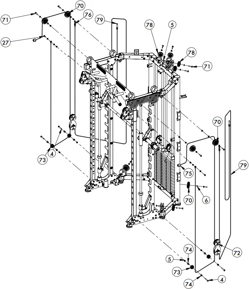
ASSEMBLY STEP 7 INSTRUCTIONS
- Install pulley (70) with M10*45 hexagon bolt (71), Ø10 flat washer (6), M10 lock nut (5) on the main frame.
- Install Ø50 pulley (73) on main frame with sleeve (74), M10*75 hexagon bolt (4), Ø10 flat washer (6) and M10 lock nut (5).
- Install the cable (75) and (79) to the main frame as shown in diagram with M10*25 hexagon bolt (27), Ø10 flat washer (6), M10 lock nut (5) and hoist hook (76).
ASSEMBLY STEP 8
No. | Description | Notes | Qty |
40 | Hexagon bolt | M8*16 | 12 |
41 | Flat washer | Ø8 | 20 |
80 | Weight plate storage | – | 6 |
81 | Spring collar | Ø50 | 6 |
82 | Shield right | – | 1 |
83 | Hexagon bolt | M6*16 | 10 |
84 | Flat washer | Ø6 | 10 |
85 | Shield rubber seal | 32*1956 | 1 |
86 | Upper left/lower right triangle trim board | – | 2 |
87 | Hexagon bolt | M8*20 | 8 |
88 | Upper right/lower left triangle trim board | – | 2 |
89 | Shield left | – | 1 |
90 | Storage hook | – | 10 |
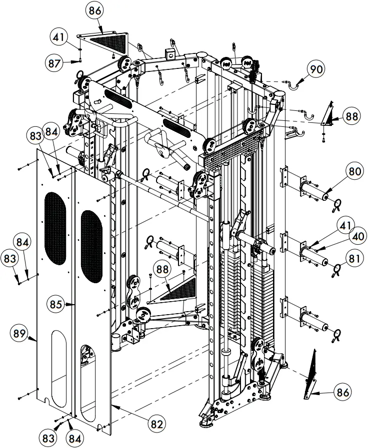
ASSEMBLY STEP 8 INSTRUCTIONS
- Install the upper left/lower right triangle trim board (86) and upper right/lower left triangle trim board (88) to the main frame with M8*20 hexagon bolt (87) and Ø8 flat washer (41).
- Install the shield right (82), shield rubber seal (85) and shield left (89) to the main frame with M6*16 hexagon bolt (83) and Ø6 flat washer (84).
- Attach all weight plate storage rod (80) to main frame with M8*16 hexagon bolt (40) and Ø8 flat washer (41)
- Spring collars (81) can be stored on weight plate storage rod (80).
- Screw in storage hooks (90) on the main frame.
ASSEMBLY STEP 9
No. | Description | Notes | Qty |
14 | Large flat washer | Ø30*Ø10*3 | 1 |
27 | Hexagon bolt | M10*25 | 1 |
91 | J hook right | – | 1 |
92 | J hook left | – | 1 |
93 | Safety arm right | – | 1 |
94 | Safety arm left | – | 1 |
95 | Foam roller anchoring system | – | 1 |
96 | Dipping handle left | – | 1 |
97 | Dipping handle right | – | 1 |
98 | Core trainer | – | 1 |
99 | Sleeve | Ø33*Ø29*Ø20*18 | 2 |
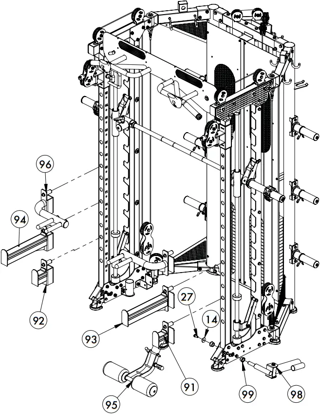
ASSEMBLY STEP 9 INSTRUCTIONS
- Use M10*25 hexagon bolt (27), Ø10 large flat washer (14) and sleeve (99) to install the core trainer (98) to the main frame.
- The j hook right (91), j hook left (92), safety arm right (93), safety arm left (94), dipping handle left (96) and dipping handle right (97) can be used on the front stainless steel posts.
ASSEMBLY STEP 10
No. | Description | Notes | Qty |
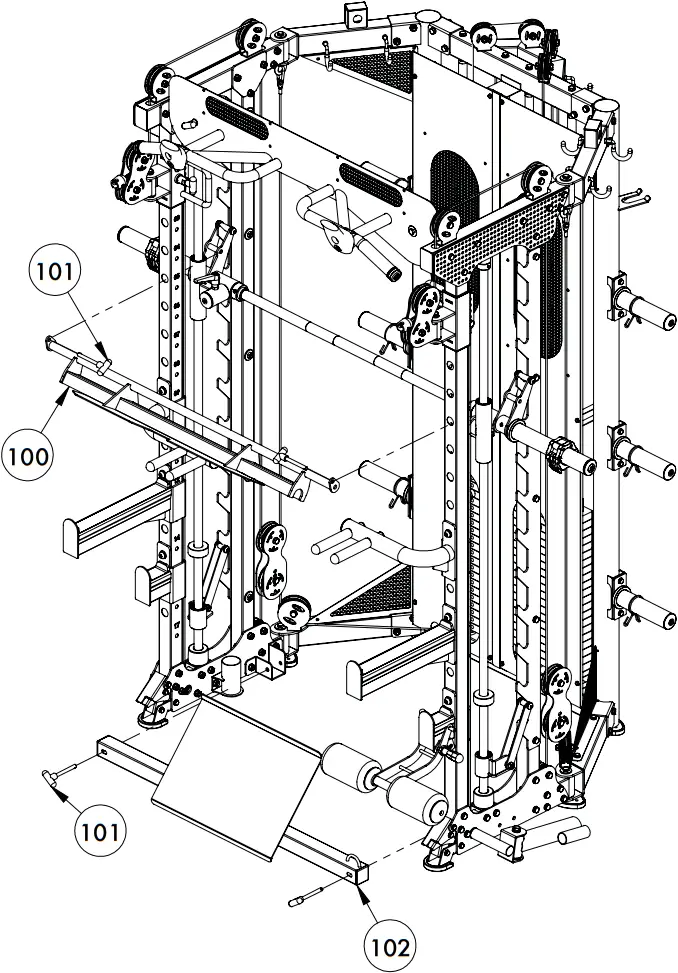
100 | Leg press plate | – | 1 |
101 | T-shape locking pin | M10*85 | 4 |
102 | Jammer arm foot plate | – | 1 |
ASSEMBLY STEP 10 INSTRUCTIONS
- Leg press plate (100) fixes to the smith machine with Ø10*85 T-shape locking pin (101).
- Use Ø10*85 T-shape locking pin (101) to secure jammer arm foot plate (102) to the main frame.
ASSEMBLY STEP 11
No. | Description | Notes | Qty |
61 | Aluminium cover | Ø50*Ø19*Ø11 | 2 |
67 | Hexagon bolt | M10*20 | 2 |
68 | Spring washer | Ø10 | 2 |
81 | Spring collar | Ø50 | 2 |
101 | T-shape locking pin | Ø10*85 | 2 |
103 | Jammer arm fixing bracket right | – | 1 |
104 | Jammer arm right | – | 1 |
105 | Jammer handle | – | 2 |
106 | Jammer arm stopper bracket right | – | 1 |
107 | Jammer arm front rod | – | 1 |
108 | Jammer arm fixing bracket left | – | 1 |
109 | Jammer arm left | – | 1 |
120 | Jammer arm stopper bracket left | – | 1 |
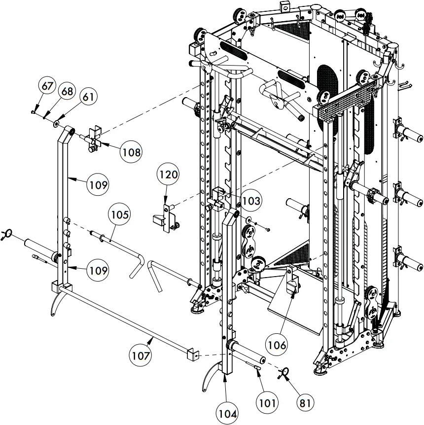
ASSEMBLY STEP 11 INSTRUCTIONS
- Connects the jammer arm fixing bracket left (108) and jammer arm left (109) with M10*20 hexagon bolt (67), Ø10 spring washer (68) and Ø50*Ø19*Ø11 aluminium cover (61).
- Connects the jammer arm fixing bracket right (103) and jammer arm right (104) with M10*20 hexagon bolt (67), Ø10 spring washer (68) and Ø50*Ø19*Ø11 aluminium cover (61).
- The jammer arm stopper bracket left and right (120) (106), hang on the front stainless steel posts when using the jammer arms.
- The jammer arm handle (105) is installed on the left and right jammer arms (104) (109).
- Use Ø10*85 T-shape pin (101) to install the jammer arm front rod (107) to both jammer arms.
ADDITIONAL ATTACHMENTS
No. | Description | Notes | Qty |
76 | Carabena | – | 8 |
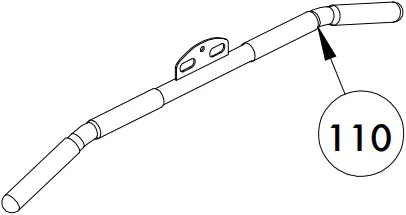
110 | Lat pull down bar | – | 1 |
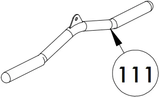
111 | Short tri-bi bar | – | 1 |
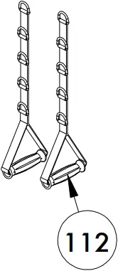
112 | D handle | – | 2 |
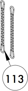
113 | Chain and Carabena | – | 2 |
114 | Tricep/bicep rope | Ø28*690 | 1 |
115 | Barbell lifting device | – | 1 |
![]()


