robustel R3000 Outdoor Gateway
Product Information
The Robustel R3000 is a hardware device designed for various wireless communication applications. It supports 2G, 3G, 4G, Wi-Fi, and GNSS technologies. The device complies with regulatory standards and has undergone type approval testing. It is manufactured by Guangzhou Robustel Co., Ltd.
Hardware Manual
- Version: 1.0.1
- Date: Nov. 22, 2022
- Manual Code: RT064_HM_R3000
Regulatory and Type Approval Information
| Name of Hazardous Substances | (Pb) | (Hg) | (Cd) | (Cr(VI)) | (PBB) | (PBDE) | (DEHP) | (BBP) | (DBP) | (DIBP) |
|---|---|---|---|---|---|---|---|---|---|---|
| Metal parts | o | o | o | o | – | – | – | – | – | – |
| Circuit modules | o | o | o | o | o | o | o | o | o | o |
| Cables and cable assemblies | o | o | o | o | o | o | o | o | o | o |
| Plastic and polymeric parts | o | o | o | o | o | o | o | o | o | o |
Note: “o” indicates that the toxic or hazardous substance is below the limit requirement in RoHS2.0, “-” indicates the absence of the substance.
Radio Specifications for Europe
The device supports the following RF technologies:
- 2G
- 3G
- 4G
- Wi-Fi
- GNSS
Cellular Frequencies
- 4G: LTE FDD:
- B1/B2/B3/B4/B5/B7/B8/B12/B13/B18/B19/B20/B25/B26/B28 LTE TDD:
- B38/B39/B40/B41
- 3G: WCDMA: B1/B2/B4/B5/B6/B8/B19
- 2G: GSM: B2/B3/B5/B8
Note: RF technologies and frequencies may vary depending on the device model. The operation of the 5150 ~ 5250 MHz frequency range is restricted to indoor use only.
Caution: Any changes or modifications not approved by the responsible party may void the user’s authority to operate the equipment.
FCC & IC Radiation Exposure Statement
The equipment complies with FCC and Canada radiation exposure limits for an uncontrolled environment. It should be installed and operated with a minimum distance of 20cm between the radiator and the user’s body. The transmitter should not be co-located or operated with any other antenna or transmitter.
Simplified EU Declaration of Conformity
The radio equipment complies with all applicable EU directives. The full text of the EU Declaration of Conformity is available at www.robustel.com/certifications/
Product Disposal The symbol indicates that the product should not be mixed with general household waste but must be sent to separate collection facilities for recovery and recycling. The symbol indicates that the product meets the requirements of the applicable EU directives. The symbol indicates that the product meets the requirements of the relevant UK legislation.
Related Downloads
Find more product documents or tools at: www.robustel.com/en/documentations/
Regulatory and Type Approval Information
Table 1: Toxic or Hazardous Substances or Elements with Defined Concentration Limits
| Name of the Part | Hazardous Substances | |||||||||
| (Pb) | (Hg) | (Cd) | (Cr(VI)) | (PBB) | (PBDE) | (DEHP) | (BBP) | (DBP) | (DIBP) | |
| Metal parts | o | o | o | o | – | – | – | – | – | – |
| Circuit modules | o | o | o | o | o | o | o | o | o | o |
| Cables and cable assemblie s |
o |
o |
o |
o |
o |
o |
o |
o |
o |
o |
| Plastic and polymeric parts |
o |
o |
o |
o |
o |
o |
o |
o |
o |
o |
| o: Indicates that this toxic or hazardous substance contained in all of the homogeneous materials for this part is below the limit requirement in RoHS2.0. X: Indicates that this toxic or hazardous substance contained in at least one of the homogeneous materials for this part might exceed the limit requirement in RoHS2.0. -: Indicates that it does not contain the toxic or hazardous substance. | ||||||||||
o:
Indicates that this toxic or hazardous substance contained in all of the homogeneous materials for this part is below the limit requirement in RoHS2.0.
X:
Indicates that this toxic or hazardous substance contained in at least one of the homogeneous materials for this part might exceed the limit requirement in RoHS2.0.
-:
Indicates that it does not contain a toxic or hazardous substance.
Radio Specifications for Europe
| RF technologies | 2G, 3G, 4G, Wi-Fi*, GNSS* |
|
Cellular Frequency* | 4G: LTE FDD: B1/B2/B3/B4/B5/B7/B8/B12/B13/B18/B19/B20/B25/B26/B28 LTE TDD: B38/B39/B40/B41 3G: WCDMA: B1/B2/B4/B5/B6/B8/B19 2G: GSM: B2/B3/B5/B8 |
| Wi-Fi Frequency | 2.4 GHz: 2.412 ~ 2.484 GHz 5 GHz: 4.910 ~ 5.825 GHz |
| Max RF power | 33 dBm±2dB@GSM, 24 dBm+1/-3dB@WCDMA, 23 dBm±2dB@LTE, 18 dBm@Wi-Fi |
May vary on different models.
Note
Operation of the 5150 ~ 5250 MHz frequency range is restricted to indoor use only.
Caution
The user is cautioned that changes or modifications not expressly approved by the party responsible for compliance could void the user’s authority to operate the equipment. This device contains license-exempt transmitter(s)/receiver(s) that comply with Innovation, Science, and Economic Development Canada’s license-exempt RSS(s) and Part 15 of the FCC Rules. Operation is subject to the following two conditions:
- This device may not cause interference.
- This device must accept any interference, including interference that may cause undesired operation of the device.
Note:
This equipment has been tested and found to comply with the limits for a Class B digital device, pursuant to Part 15 of the FCC Rules. These limits are designed to provide reasonable protection against harmful interference in a residential installation. This equipment generates, uses, and can radiate radio frequency energy and, if not installed and used in accordance with the instructions, may cause harmful interference to radio communications. However, there is no guarantee that interference will not occur in a particular installation. If this equipment does cause harmful interference to radio or television reception, which can be determined by turning the equipment off and on, the user is encouraged to try to correct the interference by one or more of the following measures:
- Reorient or relocate the receiving antenna.
- Increase the separation between the equipment and the receiver.
- connect the equipment to an outlet on a circuit different from that to which the receiver is connected.
- consult the dealer or an experienced radio /TV technician for
FCC& IC Radiation Exposure Statement
This equipment complies with FCC and Canada radiation exposure limits set forth for an uncontrolled environment. This equipment should be installed and operated with a minimum distance of 2 0cm between the radiator and your
body. This transmitter must not be co-located or operating in conjunction with any other antenna or transmitter.
Simplified EU Declaration of Conformity
We, Guangzhou Robustel Co., Ltd. are located at 501, Building #2, 63 Yongan
Road, Huangpu District, Guangzhou, China declares that this radio equipment complies with all applicable EU directives. The full text of the EU DoC is available on the following internet.
Safety Information
General
- The router generates radio frequency (RF) power. When using the router, care must be taken on safety issues related to RF interference as well as regulations of RF equipment.
- Do not use your router in aircraft, hospitals, petrol stations, or in places where using cellular products is prohibited.
- Be sure that the router will not be interfering with nearby equipment. For example pacemakers or medical equipment. The antenna of the router should be away from computers, office equipment, home appliance, etc.
- An external antenna must be connected to the router for proper operation. Only uses approved antenna with the router. Please contact the authorized distributor on finding an approved antenna.
RF Exposure - This device meets the official requirements for exposure to radio waves. This device is designed and manufactured not to exceed the emission limits for exposure to radio frequency (RF) energy set by authorized agencies.
- The device must be used with a minimum separation of 20 cm from a person’s body to ensure compliance with RF exposure guidelines. Failure to observe these instructions could result in your RF exposure exceeding the applicable
limits.
Note:
Some airlines may permit the use of cellular phones while the aircraft is on the ground and the door is open. A router may be used at this time. The symbol indicates that the product should not be mixed with general household waste but must be sent to separate collection facilities for recovery and recycling.
The symbol indicates that the product meets the requirements of the applicable EU directives. The symbol indicates that the product meets the requirements of the relevant UK legislation.
Related download link
Find more product
documents or tools at: www.robustel.com/en/documentations/
Technical Support
Tel: +86-20-82321505
Email: [email protected]
Web: www.robustel.com
Document
History
Updates between document versions are cumulative. Therefore, the latest document version contains all updates made to previous versions.
| Date | Firmware Version | Document Version | Change Description |
| Aug. 15, 2022 | 5.0.0 | 1.0.0 | Initial release. |
| Nov. 22, 2022 | 5.0.0 | 1.0.1 | Added declaration for product. |
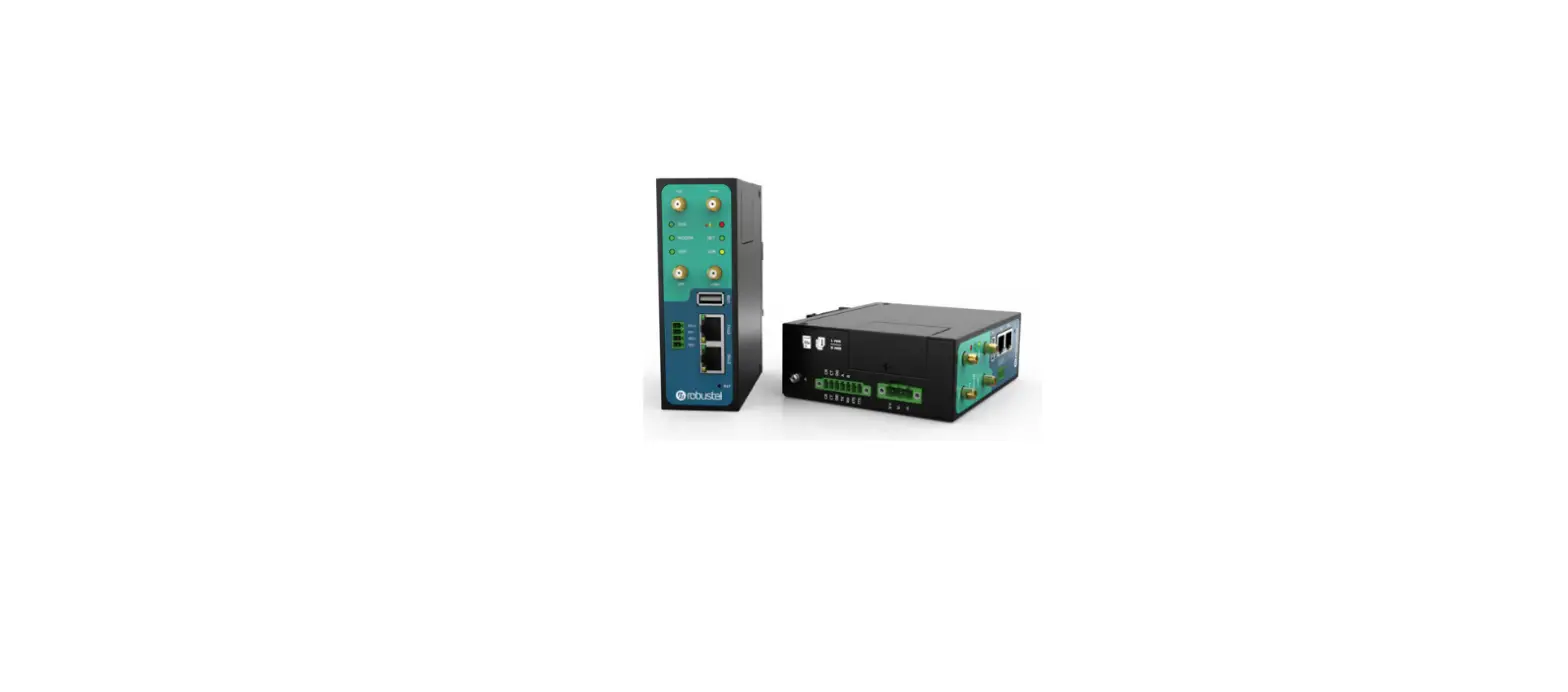
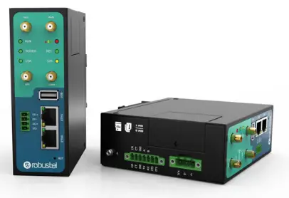
Overview
The Robustel Industrial Dual SIM Cellular VPN Router (R3000) is a rugged cellular router offering state-of-the-art mobile connectivity for machine-to-machine (M2M) applications.
Package Checklist
Before commencing installation ensure your package has the following components
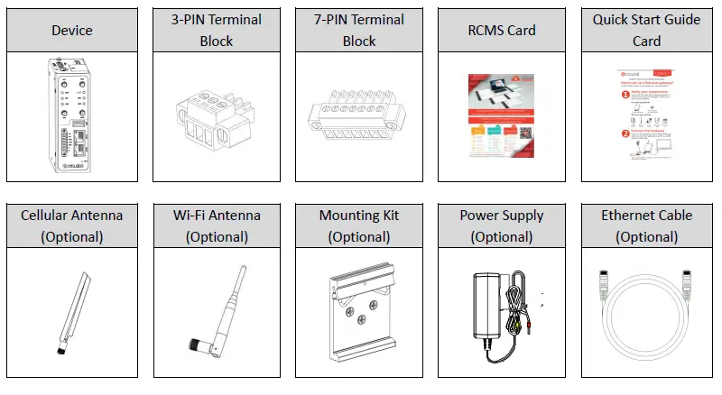
Note
The accessories could be different in a specific order.
Panel Layout(May
Vary on Different Models)
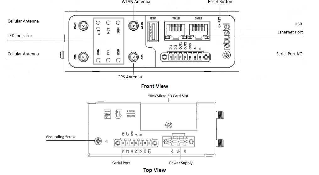
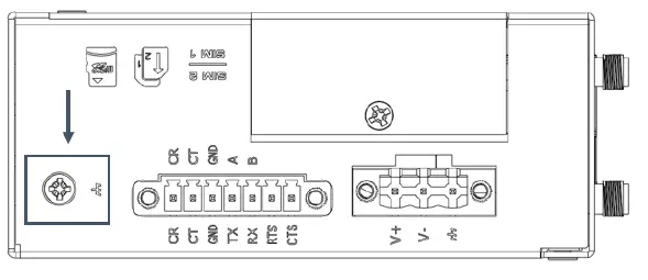
Interface Descriptions
PIN Assignment
Note: RS-232/RS-485 depends on the equipment hardware selection, please set it according to the actual situation of the equipment
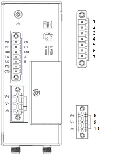
| PIN | Debug | RS-232 | Direction |
| 1 | CR | — | R3000 ¬ Device |
| 2 | CT | — | R3000 ® Device |
| 3 | GND | GND | — |
| 4 | — | TXD | R3000 ® Device |
| 5 | — | RXD | R3000 ¬ Device |
| 6 | — | RTS | R3000 ® Device |
| 7 | — | CTS | R3000 ¬ Device |
| PIN | Debug | RS-485 | Direction |
| 4 | — | Data+(A) | R3000 ® Device |
| 5 | — | Data- (B) | R3000 ¬ Device |
| PIN | Power |
| 8 | Positive |
| 9 | Negative |
| 10 | GND |
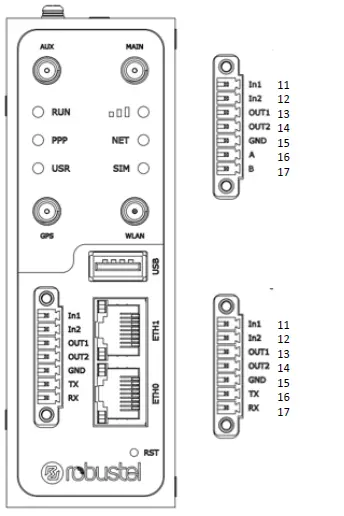
| PIN | DI/DO | RS-485 | Direction |
| 11 | Input 1 | — | R3000 ¬ Device |
| 12 | Input 2 | — | R3000 ¬ Device |
| 13 | Output 1 | — | R3000 ® Device |
| 14 | Output 2 | — | R3000 ® Device |
| 15 | GND | — | — |
| 16 | — | Data+(A) | R3000 ® Device |
| 17 | — | Data- (B) | R3000 ¬ Device |
| PIN | DI/DO | RS-232 | Direction |
| 11 | Input 1 | — | R3000 ¬ Device |
| 12 | Input 2 | — | R3000 ¬ Device |
| 13 | Output 1 | — | R3000 ® Device |
| 14 | Output 2 | — | R3000 ® Device |
| 15 | IO_GND | — | — |
| 16 | — | TXD | R3000 ® Device |
| 17 | — | RXD | R3000 ¬ Device |
| 3 | — | GND | — |
LED Indicators
| Name | Color | Status | Description |
|
RUN |
Green | On, fast blinking (250ms blink time) | Router is powered on (System is initializing) |
| On, blinking (500ms blink time) | Router starts operating | ||
| Off | Router is powered off | ||
| PPP | Green | On, solid | Link connection is working |
| Off | Link connection is not working | ||
| USR-OpenVPN | Green | On, solid | OpenVPN connection is established |
| Off | OpenVPN connection is not established | ||
| USR-IPsec | Green | On, solid | IPsec connection is established |
| Off | IPsec connection is not established | ||
| USR-Wi-Fi | Green | On, solid | Wi-Fi is enabled and working properly |
| Off | Wi-Fi is disabled or not working properly | ||
|
| Green | On, solid | High Signal strength (21-31) is available |
| Yellow | On, solid | Medium Signal strength (11-20) is available | |
| Red | On, solid | Low Signal strength (1-10) is available | |
| — | Off | No signal | |
|
NET | Green | On, solid | Connection to 4G network is established |
| Yellow | On, solid | Connection to 3G network is established | |
| Red | On, solid | Connection to 2G network is established | |
| — | Off | Connection to network is not established or establishing | |
|
SIM |
Green | On, solid | Main card is being used |
| On, blinking | Backup card is being used | ||
| Off | NO SIM card |

Note
You can choose the display type of USR LED. For more details, please refer to
RT
123 _SM_RobustOS Software Manual Service > Advanced > System >System Settings > User LED Type.
Reset Button
Ethernet Ports. There are 2 Ethernet ports on R3000 Router, including ETH0 and ETH1. Each Ethernet port has 2 LED indicators. The yellow one is a link indicator, while the green one is a speed indicator. For details about the status, see the table below.
| Feature | Operation |
| Reboot | Press and hold the RST button for 2~ 5 seconds under the operating status. |
| Restore to default configuration | Press and hold the RST button for 5~10 seconds, the RUN LED starts blinking quickly, the router will restore to default configuration. |
| Restore to factory default settings | Once the operation of restoring default configuration is performed twice within one minute, the router will restore to factory default settings. |
| Note: The more details please refer to RT123_SM_RobustOS Software Manual, 2.3 Factory Reset. | |
USB Interface
| Indicator | Status | Description |
| Link indicator | On, solid | Connection is established |
| On, blinking | Data is being transferred | |
| Off | Connection is not established | |
| Speed indicator | On, solid | 100 Mbps mode |
| Off | 10 Mbps mode |
| Feature | Operation |
| Firmware upgrade | USB interface is used for batch firmware upgrading, but cannot be used for sending or receiving data from slave devices which connected to it. You can insert a USB storage device into the router’s USB interface, such as a U disk or a hard disk. If there have a supported configuration file or a router firmware in this USB storage device, the router will automatically update the configuration file or the firmware. For more details, see RT123_SM_RobustOS Software Manual. |
Hardware Installation
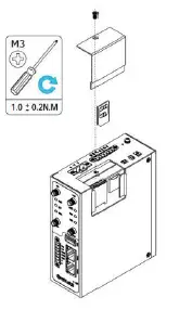
- SIM Card Installation. Loosen the screws associated with the cover by using a screwdriver and then find the SIM card slot/Micro SD card slot.

- Press the card with your finger until you hear a click and then tighten the screws associated with the cover by using a screwdriver. Put back the cover and tighten the screws associated with the cover by using a screwdriver.

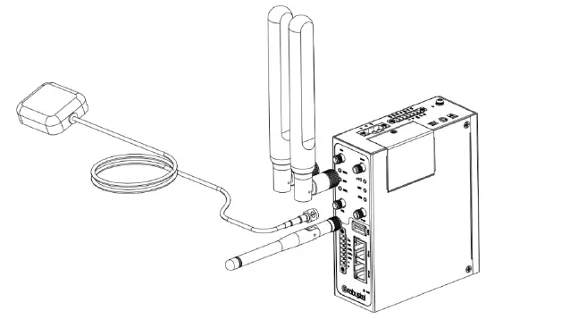
- Antenna Installation. Rotate the antenna into the antenna connector accordingly

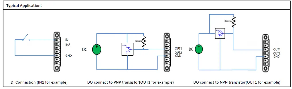
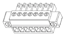
- Terminal Block Installation. Insert the terminal blocks into the interfaces connector, then can connect the devices or sensors to the gateway via corresponding interfaces e.g. RS232/RS485, DIDO…

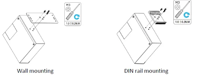
- Mounting Kit installation. (Optional)

- Grounding the Device. Grounding will help to prevent the noise effect due to electromagnetic interference (EMI). Connect the device to the site ground wire by the grounding screw before powering it on.

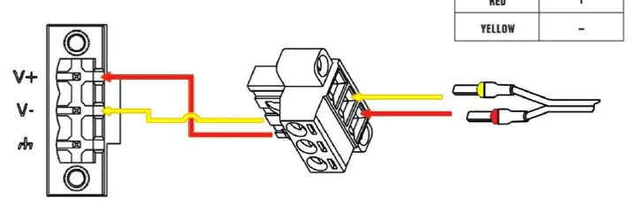
- Power Supply Installation. Following the color of the head, connect the cable marked red to the positive pole through a terminal block, and connect the yellow one to the negative in the same way. The last step is to plug the power adapter into your socket.
Note: The range of power voltage is 9 to 60V DC.
Log in to the Device
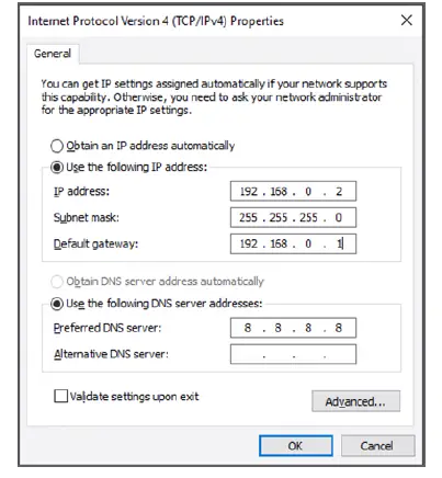
- Connect the router’s Ethernet port to a PC with a standard Ethernet cable. Before logging in, manually configure the PC with a static IP address on the same subnet as the gateway address, click, and configure “Use the following IP address”.

- To enter the gateway’s web interface, type http://192.168.0.1 into the URL field of your Internet browser.

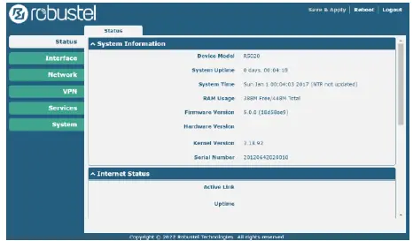
- Use login information shown in the product label when prompted for authentication.

- After logging in, the home page of the web interface is displayed, then you can view system information and perform configuration on the device
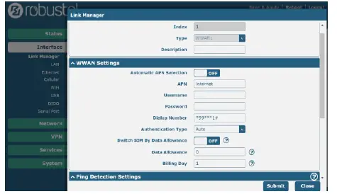
- The automatic APN selection is ON by default, if need to specify your own APN, please go to the menu Interface->Link Manager->Link Setting->WWAN Settings to finish the specific setting.

- The more configuration details please refer to RT123_SM_RobustOS Software Manual. (END)

Support
[email protected]
Website: www.robustel.com
202 2 Guangzhou Robuste l Co., Ltd.
All rights reserved. Subject to change without notice.


