
![]() SE-0115 aSENSE RL CO2 and Temperature Transmitters
SE-0115 aSENSE RL CO2 and Temperature Transmitters
Installation Guide
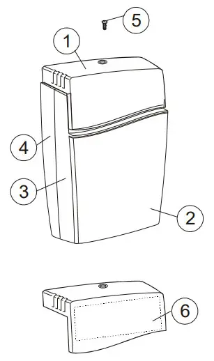
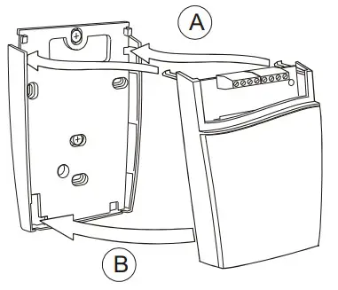
| 1 top part 2 lid 3 front part | 4 wall plate 5 screw 6 label with settings inside the top part |
Dismounting the sensor
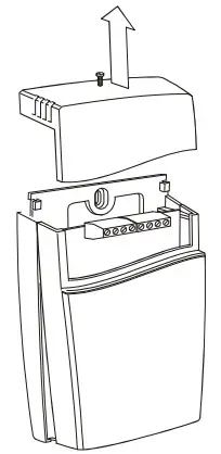 |  | 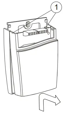 |
| Pull the top part upwards | Push the front part with the lid upwards while keeping the wall plate steady | Fold the front part with the lid forwards and lose it from the hooks (#1) |
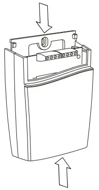
Mounting the sensor
 | 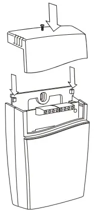 | |
| Screw head diameter: max 7.5mm (0.295 inches) Screw head height: max 2.5mm (0.1 inches) | A) Put the top tabs of the front part into the top holes of the wall plate. (B) Press the lower edge of the case on to the wall plate to latch | The top part is pushed under the locking hooks of the wall plate and is secured with a screw. |
If the connection cables are drawn through a conduit the conduit must be sealed.
The air of different temperatures may otherwise disturb the temperature measurements.
If possible keep the sensor powered up after mounting. Connect the analog output before measuring (see Electrical connections).
![]() If for some reason, the PCB must be removed, care must be taken to protect from electrostatic discharge! Normally, removing the PCB is NOT required.
If for some reason, the PCB must be removed, care must be taken to protect from electrostatic discharge! Normally, removing the PCB is NOT required.
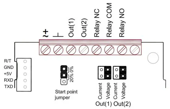
Terminals and jumpers under the top part on a sense RL. The darker positions are default settings.
Electrical connections
The power supply has to be connected to ![]() and
and ![]() .
.![]() is considered as system ground. If the analog output is connected to a controller the same ground reference has to be used for the aSENSE RL unit and for the control system! Unless different transformers are used, special precautions need to be taken.
is considered as system ground. If the analog output is connected to a controller the same ground reference has to be used for the aSENSE RL unit and for the control system! Unless different transformers are used, special precautions need to be taken.
| Connection Terminal | Function | Electrical Data | Remarks |
| Power (+) Power ground (-) | 24 VAC/DC+ (+-20%), 3W 24 VAC/DC- | 2W without output load See note 1! | |
| Out(1) CO2 Out(2) Temp | Analogue Output 1 (+) 0-2000 ppm See label for non-standard Analog Output 2 (+) 0-50 °C ppm See label for non-standard | 0-10 VDC or 0-20 mA, 2-10 VDC or 4-20 mA, Same as Output 1 | According to positions of Out(1) and start point jumpers. See note 2! According to positions of Out(2) and start point jumpers. See notes 2 and 3! |
| 5 6 7 | Normally closed relay Relay COM Normally open relay | Contact-free relay minimum load 1mA/5V rated load 0,5A/125VAC; 1A/24VDC | Triggered by register Out(3) Standard relay ON/OFF 1000/900 ppm CO2 See label for non-standard |
| 8 | Not used |
Table I. Electrical terminal connections for aSENSE RL
Note 1: The ground terminal is used as negative power supply DC input or AC phase ground ![]() (halfwave rectifier). A single transformer may be used for the entire system.
(halfwave rectifier). A single transformer may be used for the entire system.
Note 2: aSENSE RL can deliver a voltage or a current loop for Out(1)/ Out(2). To change between voltage and current output mode the hardware jumpers are used. There is one jumper for Out(1) and one for Out(2), so that one output can be a voltage output and the other a current output. Both, voltage output and current output can have start points O % (0-1 O VDC or 0-20mA) or 20 % (2-10 VDC or 4-20mA). The same starting point is used for both outputs. See the function manual.
Note 3: Please use voltage outputs for temperature measurements. The accuracy of temperature measurements is valid only for units configured in voltage outputs mode.
Senseair® AB (headquarter)
Stationsgatan 12
Phone: +46-(0)653-71 77 70
Box 96
E-mail; [email protected]
824 08 Delsbo
SWEDEN Web site: www.senseair.com


