![]() CT1R Select Series Room CO2 Transmitters
CT1R Select Series Room CO2 Transmitters
Installation Guide
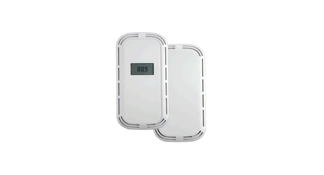
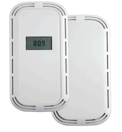 Room CO2 & CO2/T Transmitters
IMPORTANT WARNINGS
- Only qualified trade installers should install this product
- This product is not intended for life-safety applications
- Do not install in hazardous or classified locations
- The installer is responsible for all applicable codes
- De-energize power supply prior to installation or service
PRODUCT APPLICATION LIMITATION:
Senna products are not designed for life or safety applications.
Senna products are not intended for use in critical applications such as nuclear facilities, human implantable device or life support. Senna is not liable, in whole or in part, for any claims or damages arising from such uses.
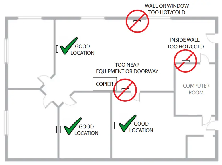
INSTALLATION
- IMPORTANT! Locate sensor in an area away from ventilation sources and heat generating equipment and appliances. Sensor should be mounted at light switch height in a vertical orientation. Use insulating material behind sensor to ensure reading accuracy.
NOTE: Do not install sensor in multi-gang electrical boxes with line voltage or other electrical devices.

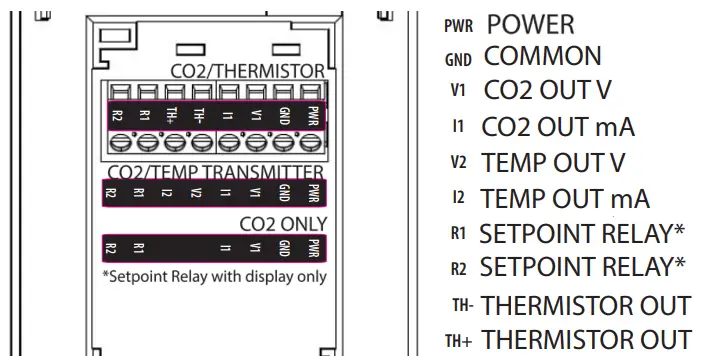
- Wire sensor as shown above.
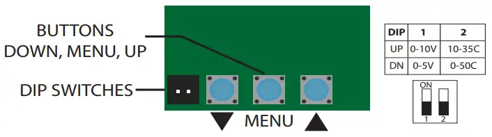
- Set DIP switch positions to accommodate your application. DIP switch 2 only applies to units with transmitter temperature output selected.

- See mounting section.
- Apply power to sensor.
OPERATION
Press center MENU button to cycle between:![]() Scaling “2” = 2000ppm, “5” = 5000ppm, “10” =10000ppm
Scaling “2” = 2000ppm, “5” = 5000ppm, “10” =10000ppm![]() *Setpoint, Hi (Closed above this level)
*Setpoint, Hi (Closed above this level)![]() *Setpoint, Lo (Open below this level)
*Setpoint, Lo (Open below this level)![]() Manual calibration adjustment +/-250ppm
Manual calibration adjustment +/-250ppm![]() **Automatic calibration – ON/OFF
**Automatic calibration – ON/OFF
The upper arrow▲ and lower▼ arrow will show the current setting and then adjusted values on consecutive presses.
For No Display:
0-2000ppm output and ABC is ON
* Relay only available with Display.
**For continuously occupied areas or greenhouses, it is recommended to turn automatic calibration to ‘off’. CT1R-XXX-D (Dual Channel CO2) products will have with calibration ‘off’ by default.
TROUBLESHOOTING
| Symptom | Solution |
| No output | Check wiring. Ensure power supply meets requirements. |
| CO2 reading error | Verify control panel software is configured for correct output scaling. |
| Verify accuracy of test instrument. Observe installation and calibration guidelines | |
| Install insulation foam gasket provided to prevent thermal conduction from inside wall. | |
| Perform calibration only if necessary. |
MOUNTING
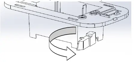
IF MOUNTING INTO A JUNCTION BOX:
1. Remove drywall clamps by turning screws counter clockwise.
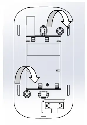
IF MOUNTING INTO DRYWALL:
- Turn both mounting clamps all the way counter clockwise.

- Insert into drywall cutout.
- Turn screws clockwise to tighten drywall mounts until tight to wall.

CALIBRATION
Automatic Calibration feature:
The sensor will automatically track low ambient CO2 levels and gradually make adjustments to compensate for sensor drift due to long-term aging of the IR light source. In applications where CO2 levels are continuously elevated, or spaces are occupied day and night, it is recommended to use our dual channel CO2 sensor with ABC disabled.
Senna CO2 sensors are factory calibrated to controlled test gases. No field calibration is necessary or recommended.
However, to facilitate compliance with job requirements and commissioning procedures, provisions for field calibration are provided:
- Locate calibration instrument and sensor in close proximity to each other in a controlled environment free of drafts, people, and equipment to reduce influence on CO2 and temperature.
- Compare output of sensor to calibration instrument, and note difference. (In 0-10V mode/2000ppm range, 1V =200ppm)
- Using the buttons on front of unit, adjust offset value for CO2 as needed. Factory calibration may be restored by setting offset back to 0.
SPECIFICATIONS
| Power supply | AC Supply/DC Supply | 24VAC (1) 100mA max / 12-30VDC, 50mA max |
| Outputs | CO2 and Temperature (option) | 3-wire 4-20mA, 0-5V or 0-10V (2) (selectable) |
| Relay | Solid state, 1A@30VAC/DC, N.O. (3) | |
| Output scaling | CO2 | 0-2000ppm (default), 0-5000ppm or 10,000ppm (selectable) |
| CO2 Sensor Performance
| Type | Non-dispersive Infrared (NDIR) |
| Accuracy (Standard) | ±(30ppm +3% of reading) (400-2000ppm), @-10-50°C ±(50ppm +5% of reading) (2000-5000ppm), @-10-50°C ±(100ppm+10% of reading) (5000-10000ppm), @ 0-50C | |
| Accuracy (Dual Channel) | ±(30ppm+3% of reading) (0-2000ppm), @ 0-50C ±(50ppm+3% of reading) (2000-5000ppm), @ -10-50C ±(100ppm+10% of reading) (5000-10000ppm), @ 0-50C | |
| Drift with ABC disabled (Standard) | 35ppm/month (4) | |
| Drift with ABC disabled (Dual Channel) | 5ppm/month (5) | |
| Range | 0-2000/5000ppm; Programmable up to 10,000ppm | |
| Response time | 60s to 90% reading | |
| Output update rate | 1s | |
| Element Operating Environment(4) | 14 to 122ºF (-10 to 50ºC), 0 to 95% RH | |
|
Temperature Transmitter
| Accuracy | <±0.2oC |
| Resolution | 0.01oC | |
| Repeatability | 0.04oC | |
| Response time | 2s | |
| Output update rate | 0.5s | |
| Element Operating range | -40 to 140oF (-40 to 60oC) | |
| Environmental
| Enclosure Rating | IP20/NEMA 1 |
| Dimensions | 5.66”h x 3.00”w x 0.36”d (1.69”d including recessed portion) | |
| Max Operating Temp | 14 to 122oF (-10 to 50oC) |
- One side of transformer secondary is connected to signal common. Dedicated transformer is recommended.
- 15-30VDC/24VAC power supply voltage required for 10 Volt output.
- Relay only available with display.
- It is not recommended to de-activate ABC (auto-calibration) except for continuously occupied spaces or greenhouses. Drift ratings may vary based on environment.
- Operation outside of element operating environment may result in reduced accuracy.
![]() senvainc.com
senvainc.com
1-866-660-8864
1825 NW 167th Place Beaverton Oregon 97006


