VTSCO2-SENS-D-MODRTU CO2 Concentration Transducer
CO2 Transducer CO2-SENS-D-MODRTU
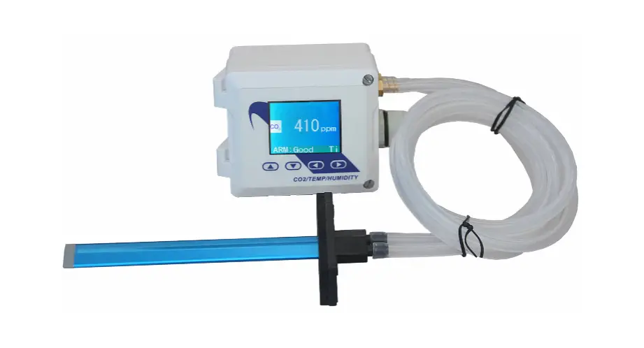
The CO2 Transducer CO2-SENS-D-MODRTU is designed to measure the concentration of CO2 in the air using an integrated MH-Z19B sensor.
The device is equipped with an RS-485 interface using the MODBUS RTU protocol and 0-5V / 0-10V analog output. It is suitable for use in various applications such as HVAC systems, greenhouses, and indoor air quality monitoring.
Functions of the Device
- CO2 measurement
- 0-5V or 0-10V analogue output (hardware selectable range) proportional to CO2 concentration
- 3 status LEDs
- RS485 serial interface for remote management (setup and reading of measurement values)
- MODBUS RTU protocol
- Integrated terminating resistor 120
- Communication in HALF DUPLEX mode
- Hardware/software configurable address in the range 1-247
- Hardware configurable communication baud rate: 19200, 9600, 4800, 2400
- Software configurable communication baud rate: 115200, 57600, 38400, 19200, 9600, 4800, 2400
Technical Data
General Parameters of the Transducer
- Power supply: DC voltage 20-30 V (nom DC 24 V) or AC voltage 20-28 V (nom AC 24 V)
- Current consumption: 30 mA typical, 100 mA max
- LED indicators
- Signal connection: Screw terminals in 5 mm pitch (wire diameter 2.5 mm)
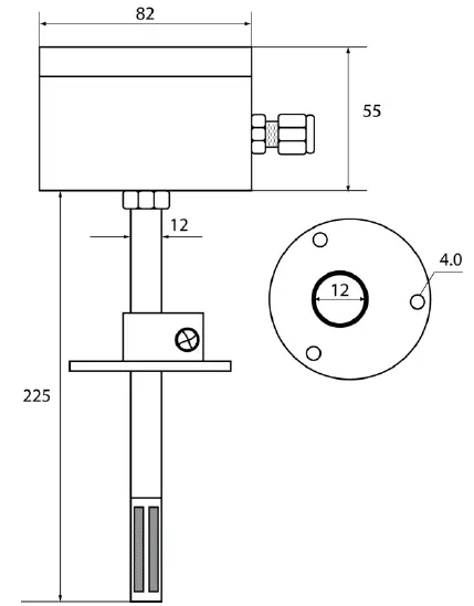
- Housing dimensions: 80x82x55 mm without sampling mast, 80x82x280 mm with sampling mast
- Weight: 230g
- Working environment: Dust-free, air, neutral gases
- Working temperature: -10°C to 50°C
Parameters of CO2 Measurement
- Sensor model: MH-Z19B
- Measurement range: 0/400-2000 ppm
- Measurement accuracy: ±50 ppm ±3% of reading value (in the range of 400-2000 ppm)
- Sampling period: 5 s
- Response time T90*: <2 min (*response time T90 is the time from moment of change of state to the moment when the measurement value reaches 90% of the steady value.)
Parameters of Analog Output
- Output type: voltage 0-5 V or 0-10 V
- Output range resolution in mV: for the range 0-10 V – 3.2 mV, for the range 0-5 V – 1.6 mV
- Loading capacity: RL >1 kΩ
- Refreshing period: 1 s
Parameters of Serial Interface
- Transmission interface: RS-485
- Communication protocol: MODBUS RTU
- Transmission type: HALF DUPLEX
- Communication baud rate: 2400 / 4800 / 9600 / 19200 / 38400 / 57600 / 115200 Baud/s
- Integrated resistor terminating the RS-485 bus: 120 Ω
Installation Instructions
It is important to read the user manual carefully before attempting to start up the device. The CO2 transducer must be installed by qualified staff only. All connections must be made in accordance with wiring diagrams.
- Choose a suitable location for the transducer, taking into account the working environment and temperature requirements.
- Mount the transducer on a wall, using screws or other appropriate fixings.
- Connect the power supply according to the wiring diagram, making sure to connect the correct polarity.
- Connect the signal wires according to the wiring diagram.
- Configure the device’s address and communication baud rate according to your requirements.
- Once the device is properly installed and configured, it will start measuring CO2 concentration and outputting data through the analog and serial interfaces.
VTS reserves the right to implement changes without prior notice. www.vtsgroup.com Page 1 of 16 ver. 2.0 (11.2021)
Introduction
This document describes functionality of CO2 concentration transducer based on integrated MH-Z19B sensor, equipped with RS-485 interface using MODBUS RTU protocol and 0-5V / 0-10V analogue output.
NOTES:
- Read this document carefully before attempting to start up the device!
- The device must be installed by qualified staff only.
Functions of the device
- CO2 measurement
- 0-5V or 0-10V analogue output (hardware selectable range) proportional to CO2 concentration
- 3 status LEDs
- RS485 serial interface for remote management (setup and reading of measurement values)
- MODBUS RTU protocol
- integrated terminating resistor 120Ω
- communication in HALF DUPLEX mode
- hardware/software configurable address in the range 1-247
- hardware configurable communication baud rate: 19200, 9600, 4800, 2400
- software configurable communication baud rate: 115200, 57600, 38400, 19200, 9600, 4800, 2400
Device characteristics
The main function of the CO2 transmitter is to measure the CO2 concentration in the air using an integrated MH-Z19B sensor. The measurement result, as well as the sensor missing/error status, is processed by the built-in microprocessor and then made available on the RS-485 bus via registers of the MODBUS RTU protocol. Additionally, the measurement result is available as analog signal on the 0-5V / 0-10V voltage output.
Technical data
General parameters of the transducer
| Power supply | |
| · DC voltage | DC 20-30 V (nom DC 24 V) |
| · AC voltage | AC 20-28 V (nom AC 24 V) |
| Current consumption | |
| · typical | 30 mA |
| · max | 100 mA |
| LED indicators | See section 3.5 |
| Signal connection | Screw terminals in 5 mm pitch (wire diameter ≤ 2.5 mm) |
| Housing dimensions | |
| · without sampling mast | 80x82x55 mm |
| · with sampling mast | 80x82x280 mm |
| Weight | 230g |
| Working environment | Dust-free, air, neutral gases |
| Working temperature | 0ºC ÷ 50ºC |
* response time T90 is the time from moment of change of state to the moment when the measurement value reaches 90% of the steady value.
Parameters of analogue output
| Sensor model | MH-Z19B |
| Measurement range | 0/400-2000 ppm |
| Measurement accuracy | ± (5% of measured value + 50ppm) |
| Sampling period | 5 s |
| Response time T90 *) | < 2 min |
Parameters of serial interface
| Output type | voltage |
| Output range | 0-5 V or 0-10 V |
| Resolution | 11.5 bit |
| · in [mV] for the range 0-10 V | 3.2 mV~ |
| · in [mV] for the range 0-5 V | 1.6 mV~ |
| Loading capacity | RL > 1 kΩ |
| Refreshing period | 1 s |
Installation
Safety
- The device must be installed by qualified staff only!
- All connections must be made in accordance with wiring diagrams shown in this document!
- Check all electrical connections prior to commissioning!
Device design
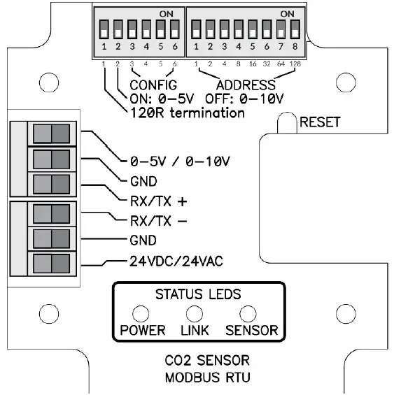
Description of terminals
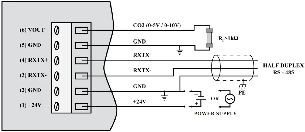
Notes:
- The RXTX+ and RXTX- signals must be connected to the A and B lines of the MODBUS bus respectively.
- The analogue output returns following voltage values:

whereas the concentration value can be calculated basing on the voltage value form using the following formula:

where:
VOLTAGERANGE = 5V or 10V (0-5V or 0-10V set on the configuration DIP-switch 2 – see section 3.4)
Exemplary values are shown in the table below:
| CO2 concentration [ppm] | Voltage range = 5 V | Voltage range = 10V |
| 0 | 0.0V | 0.0V |
| 400 | 1.0V | 2.0V |
| 1000 | 2.5V | 5.0V |
| 2000 | 5.0V | 10.0V |
Configuration of MODBUS bus, serial port and analogue output
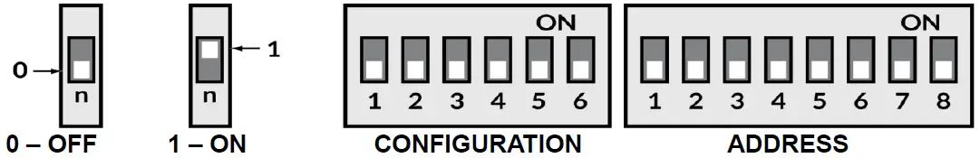
The purpose of the consecutive switches of the left DIP-switch is as follows (default values are in bold)
| 1 | 2 | 3 | 4 | 5 | 6 | Effect |
| ON | Terminating resistor 120R switched on | |||||
| OFF | Terminating resistor 120R switched off | |||||
| ON | Analogue output range 0-5V | |||||
| OFF | Analogue output range 0-10V | |||||
| ON | ON | Use BAUDRATE and PAR from the software configuration | ||||
| ON | OFF | PAR – parity check (1 STOP bit) | ||||
| OFF | ON | PAR – no parity check (2 STOP bits) | ||||
| OFF | OFF | PAR – no parity check (1 STOP bit) | ||||
| ON | ON | BAUDRATE=2400 | ||||
| ON | OFF | BAUDRATE=4800 | ||||
| OFF | ON | BAUDRATE=9600 | ||||
| OFF | OFF | BAUDRATE=19200 |
The device address on the MODBUS bus is set using the right DIP-switch:
| 1 | 2 | 3 | 4 | 5 | 6 | 7 | 8 | Effect |
| ON | Address = address + 1 | |||||||
| ON | Address = address + 2 | |||||||
| ON | Address = address + 4 | |||||||
| ON | Address = address + 8 | |||||||
| ON | Address = address + 16 | |||||||
| ON | Address = address + 32 | |||||||
| ON | Address = address + 64 | |||||||
| ON | Address = address + 128 |
Note: the configuration set by the means of DIP-switches is read once after device restart (after switching on the power or pressing the RESET button). For this reason, if the DIP-switch settings are changed during operation, then after changing the settings, it is necessary to restart the device by pressing the RESET button or temporarily unplugging the power supply.
LED indicators
LED POWER
| No. | Description | Color / mode of light |
| 1 | Power supply present | Red – flashing 1000 ms / 1000 ms |
LED LINK
| No. | Description | Color / mode of light |
| 1 | Data transmission on the bus | Green – continuous light / irregular flashing |
| 2 | No transmission | LED off |
LED SENSOR
| No. | Description | Color / mode of light |
| 1 | Warm up of the CO2 module | Green – flashing 250 ms / 250 ms |
| 2 | 0 – 799 ppm | Green – continuous light |
| 3 | 800 – 1199 ppm | Yellow – continuous light |
| 4 | 1200 – 1999 ppm | Red – continuous light |
| 5 | ≥ 2000 ppm | Red – flashing 1000 ms / 1000 ms |
| 6 | Sensor missing or other error | Red – flashing 100 ms / 600 ms |
Recommendations for installation
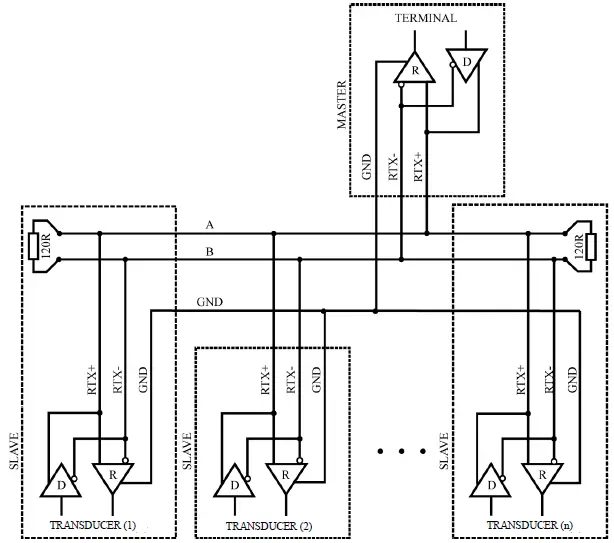
It is recommended that devices on the MODBUS (RS485) are connected in a daisy-chain configuration, whereby 120R terminating resistors should be connected between A and B lines of the bus at both ends of the chain (close to the outer devices). This resistor is built-in in the CO2-SENS-D-MODBRTU transducer and can be switched on using the no. 1 switch on the configuration DIP-switch (see section 3.4).
Moreover, shielded cables should be used when the device is operated in high interference environments and the shield should be connected to the nearest PE point on the power supply side.
The automatic zero calibration (ABC logic function)
It is assumed that CO2 concentration in the outdoor air amounts to 400 – 500 ppm. The CO2 concentration inside buildings is higher, mainly due to the presence of people. When there are no people in the building and the ventilation systems works properly, the CO2 concentration inside the building decreases to a level close to those of outdoor air.
VTS reserves the right to implement changes without prior notice.
www.vtsgroup.com of 16 ver. 2.0 (11.2021)
ABC logic is an algorithm for long term tracking of CO2 concentration and adjusting the sensor characteristics in the low concentration range. The sensor stores low values of CO2 concentration from many last days, which enables taking intelligent account of periodical CO2 concentration level increases (e.g. when rooms were used 24 hours per day over a few days). As a result of the ABC logic algorithm, the “automatic zero calibration” of the sensor is carried out.
The automatic calibration ABC logic, is designed for applications where rooms remain unoccupied for several hours per day, as a result, CO2 concentration values periodically drop to low values, similar to those outside the building. In contrast, in an environment where the level of CO2 concentration reaches high values and doesn’t drop to low values, the ABC logic system should be switched off, because it would adjust automatic calibration to the lowest levels, distorting the values indicated by the sensor.
In the sensor described in this document, the ABClogic function is off by default (factory setting). The status of ABClogic function (switching on or off) can be changed by writing the respective command (see section 4.1.1).
MODBUS protocol
Register map
| Register no. | R/W | Name | Values | Notes |
| 0x0000 | R | VALUE_REG | 0 – 2000 | CO2 concentration in [ppm] |
| 0x0001 | R | STATUS_REG | 0 / 1 / 2 / 3 | 0-Sensor missing, 1 – correct operation, 2 – sensor error, 3 – warm up (first 3 minutes after start) |
| 0x0002 | R | TEST_VAL_REG | 1000 (0x3E8) | Test value – to verify the correctness of register readings |
| 0x0003 | RW | PASS_REG | 1234 (0x04D2) | password register |
| 0x0004 | RW | COMMAND_REG | 1 / 2 / 3 / 4 / 5 / 6 | command register |
| 0x0005 | RW | PARAM_REG | Refer to command table | parameter register |
| 0x0006 | R | — | 0 | reserved |
| 0x0007 | R | — | 0 | reserved |
| 0x0008 | R | — | 0 | reserved |
| 0x0009 | R | — | 0 | reserved |
| 0x000A | R | — | 0 | reserved |
| 0x000B | R | DEV_ID_REG | 0xC100 | Device identification |
| 0x000C | R | SOFT_VER_REG | 0 – 0x9999 | Software version (e.g. 0x3210 means software 3.21a) |
Command table:
| Command no. | Function | Parameters |
| 1 | Set device address | 1-247 (1 – default value) |
| 2 | Set the baud rate | 24 – 2400 bit/s 48 – 4800 bit/s 96 – 9600 bit/s 192 – 19200 bit/s = default value 384 – 38400 bit/s 576 – 57600 bit/s 1152 – 115200 bit/s |
| 3 | Set parity bits | 0 – NO PARITY, no parity bit (default value) 1 – EVEN PARITY 2 – ODD PARITY |
| 4 | Set stop bits | 1 – 1x STOP, 1 stop bit (default value) 2 – 2x STOP, 2 stop bits |
| 5 | Function on / off | 0 – ABC logic off (off by default) 1 – ABC logic on |
| 6 | Device reset | 1 – software reset of the device 2 – software reset of sensor module |
Notes:
- Reading registers from addresses not listed in this table results in 0x02 exception.
- Specifying an incorrect or out-of-range parameter value results in entering the value 0xEEEE into the command register.
- The device is configured by writing three registers (password / command /parameter) at the same time using the 0x10 function with the corresponding values
- according to the command table, or by writing single registers (using 0x06 or 0x10 function) with the latter writing of a (valid) password causing the execution of the command.
- During a single password entry (both with function 0x06 and 0x10) in case of a password match, the correctness of information in command and parameter registers is checked and if correct, the command is executed.
DEV_ID_REG (addr=11=0x000B) – read only
| Bit no. | 15 | 14 | 13 | 12 | 11 | 10 | 9 | 8 | 7 | 6 | 5 | 4 | 3 | 2 | 1 | 0 |
| name | DEV[4..0] | HV[1..0] | OPTIONS[4..0] | 0 | 0 | T[1..0] | ||||||||||
This register is used to store device ID. Meaning of bits:
DEV[4..0] = b11000 – fixed value meaning “air parameter sensors” HV[1..0] – value 0..3 – hardware version
OPTIONS[4..0] – values 0..31 – device type b10000 – CO2 transducer with MH-Z19B sensor
T[1..0] – value 0..3 – type
- 0 – duct type
- 1 – room type
- 2, 3 – reserved
CO2 duct sensor in basic hardware version returns the value b1100000100000000=0xC100.
SOFT_VER_REG (addr=12=0x000C) – read only
| Bit no. | 15 | 14 | 13 | 12 | 11 | 10 | 9 | 8 | 7 | 6 | 5 | 4 | 3 | 2 | 1 | 0 |
| name | N[3..0] | A[3..0] | B[3..0] | REV[3..0] | ||||||||||||
Software version is represented as a sting of 4 characters: N.ABrev where
N, A, B are digits in the the 0..9 range rev (with values 0..9) is a letter in the range ‘a’…’j’.
Examples:
0x0000 represents software version: 0.00a; 0x4321 → 4.32b ; 0x2345 → 2.34f
Protocol functions
| CODE | Name |
| 0x03 (dec 3) | Reading N x 16-bit registers |
| 0x06 (dec 6) | Writing single 16-bit registers |
| 0x10 (dec 16) | Writing N x 16-bit registers |
Reading the contents of a group of output registers (0x03) Command format:
| Description | Size [Bytes] | Values | Notes |
| Address | 1 | 1 – 247 | |
| Function code | 1 | 0x03 | |
| Data block address | 2 | 0x0000 – 0xFFFF | |
| Number of registers (N) | 2 | 1 – 125 | |
| CRC check sum | 2 | 0x0000 – 0xFFFF | See section 4.4 |
Response format:
| Description | Size [Bytes] | Values | Notes |
| Address | 1 | 1 – 247 | |
| Function code | 1 | 0x03 | |
| Byte counter | 1 | 2* n | |
| Register values | 2 * N | Acc. to register map | |
| CRC check sum | 2 | 0x0000 – 0xFFFF | See section 4.4 |
Error format:
| Description | Size [Bytes] | Values | Notes |
| Address | 1 | 1 – 247 | |
| Function code | 1 | 0x83 | |
| Error code | 1 | 1– 4 | See section 4.2.4 |
| CRC check sum | 2 | 0x0000 – 0xFFFF | See section 4.4 |
Writing single 16-bit registers (0x06) Command format:
| Description | Size [Bytes] | Values | Notes |
| Address | 1 | 1 – 247 | |
| Function code | 1 | 0x06 | |
| Register address | 2 | 0x0000 – 0xFFFF | |
| Value to be stored | 2 | 0x0000 – 0xFFFF | |
| CRC check sum | 2 | 0x0000 – 0xFFFF | See section 4.4 |
Response format:
| Description | Size [Bytes] | Values | Notes |
| Address | 1 | 1 – 247 | |
| Function code | 1 | 0x06 | |
| Register address | 2 | 0x0000 – 0xFFFF | |
| Value to be stored | 2 | 0x0000 – 0xFFFF | |
| CRC check sum | 2 | 0x0000 – 0xFFFF | See section 4.4 |
Error format:
| Description | Size [Bytes] | Values | Notes |
| Address | 1 | 1 – 247 | |
| Function code | 1 | 0x86 | |
| Error code | 1 | 1 – 4 | See section 4.2.4 |
| CRC check sum | 2 | 0x0000 – 0xFFFF | See section 4.4 |
Writing a group of output registers (0x10) Command format:
| Description | Size [Bytes] | Values | Notes |
| Address | 1 | 1 – 247 | |
| Function code | 1 | 0x10 | |
| Data block address | 2 | 0x0000 – 0xFFFF | |
| Number of registers (N) | 2 | 1 – 123 | |
| Byte counter | 1 | 2 * N | |
| Values to be stored | 2 * N | 0x0000 – 0xFFFF | |
| CRC check sum | 2 | 0x0000 – 0xFFFF | See section 4.4 |
Response format:
| Description | Size [Bytes] | Values | Notes |
| Address | 1 | 1 – 247 | |
| Function code | 1 | 0x10 | |
| Data block address | 2 | 0x0000 – 0xFFFF | |
| Number of registers (N) | 2 | 1 – 123 | |
| CRC check sum | 2 | 0x0000 – 0xFFFF | See section 4.4 |
Error format:
| Description | Size [Bytes] | Values | Notes |
| Address | 1 | 1 – 247 | |
| Function code | 1 | 0x90 | |
| Error code | 1 | 1 – 4 | See section 4.2.4 |
| CRC check sum | 2 | 0x0000 – 0xFFFF | See section 4.4 |
Description of errors
| CODE | Name |
| 0x01 | Invalid function |
| 0x02 | Invalid data range / address |
| 0x03 | Invalid data value |
| 0x04 | SLAVE device error |
Data format
Character / byte format
The following figure shows the format of a byte transmitted in the MODBUS RTU protocol. Each transmitted character has 10 or 11 bits, which are sent in order from the least significant to the most significant.
With even / odd parity check
| START | 1 | 2 | 3 | 4 | 5 | 6 | 7 | 8 | PAR | STOP |
Without parity check (1 or 2 stop bits):
| START | 1 | 2 | 3 | 4 | 5 | 6 | 7 | 8 | STOP | (STOP) |
Order of bytes in 16-bit data fields in a transmission frame
The following figure shows the byte order of the 16-bit data fields. For 16-bit data fields, the correct byte order is that the older byte is transmitted first, then the younger byte (HI→LO – BIG ENDIAN), while for the CRC field the younger byte is transmitted first, then the older byte (LO→ HI – LITTLE ENDIAN).
| DATA | CHECK SUM | ||||||||
| REG-0 (16bit) | REG-1 (16 bit) | … | REG-N (16bit) | CRC (16bit) | |||||
| HI | LO | HI | LO | HI | LO | LO | HI | ||
CRC check sum
WORD CRC16 (const BYTE *nData, WORD wLength)
{
static const WORD wCRCTable[] = {
0x0000, 0xC0C1, 0xC181, 0x0140, 0xC301, 0x03C0, 0x0280, 0xC241, 0xC601, 0x06C0, 0x0780, 0xC741, 0x0500, 0xC5C1, 0xC481, 0x0440, 0xCC01, 0x0CC0, 0x0D80, 0xCD41, 0x0F00, 0xCFC1, 0xCE81, 0x0E40, 0x0A00, 0xCAC1, 0xCB81, 0x0B40, 0xC901, 0x09C0, 0x0880, 0xC841, 0xD801, 0x18C0, 0x1980, 0xD941, 0x1B00, 0xDBC1, 0xDA81, 0x1A40, 0x1E00, 0xDEC1, 0xDF81, 0x1F40, 0xDD01, 0x1DC0, 0x1C80, 0xDC41, 0x1400, 0xD4C1, 0xD581, 0x1540, 0xD701, 0x17C0, 0x1680, 0xD641, 0xD201, 0x12C0, 0x1380, 0xD341, 0x1100, 0xD1C1, 0xD081, 0x1040, 0xF001, 0x30C0, 0x3180, 0xF141, 0x3300, 0xF3C1, 0xF281, 0x3240, 0x3600, 0xF6C1, 0xF781, 0x3740, 0xF501, 0x35C0, 0x3480, 0xF441, 0x3C00, 0xFCC1, 0xFD81, 0x3D40, 0xFF01, 0x3FC0, 0x3E80, 0xFE41, 0xFA01, 0x3AC0, 0x3B80, 0xFB41, 0x3900, 0xF9C1, 0xF881, 0x3840, 0x2800, 0xE8C1, 0xE981, 0x2940, 0xEB01, 0x2BC0, 0x2A80, 0xEA41, 0xEE01, 0x2EC0, 0x2F80, 0xEF41, 0x2D00, 0xEDC1, 0xEC81, 0x2C40, 0xE401, 0x24C0, 0x2580, 0xE541, 0x2700, 0xE7C1, 0xE681, 0x2640, 0x2200, 0xE2C1, 0xE381, 0x2340, 0xE101, 0x21C0, 0x2080, 0xE041, 0xA001, 0x60C0, 0x6180, 0xA141, 0x6300, 0xA3C1, 0xA281, 0x6240, 0x6600, 0xA6C1, 0xA781, 0x6740, 0xA501, 0x65C0, 0x6480, 0xA441, 0x6C00, 0xACC1, 0xAD81, 0x6D40, 0xAF01, 0x6FC0, 0x6E80, 0xAE41, 0xAA01, 0x6AC0, 0x6B80, 0xAB41, 0x6900, 0xA9C1, 0xA881, 0x6840, 0x7800, 0xB8C1, 0xB981, 0x7940, 0xBB01, 0x7BC0, 0x7A80, 0xBA41, 0xBE01, 0x7EC0, 0x7F80, 0xBF41, 0x7D00, 0xBDC1, 0xBC81, 0x7C40, 0xB401, 0x74C0, 0x7580, 0xB541, 0x7700, 0xB7C1, 0xB681, 0x7640, 0x7200, 0xB2C1, 0xB381, 0x7340, 0xB101, 0x71C0, 0x7080, 0xB041, 0x5000, 0x90C1, 0x9181, 0x5140, 0x9301, 0x53C0, 0x5280, 0x9241, 0x9601, 0x56C0, 0x5780, 0x9741, 0x5500, 0x95C1, 0x9481, 0x5440, 0x9C01, 0x5CC0, 0x5D80, 0x9D41, 0x5F00, 0x9FC1, 0x9E81, 0x5E40, 0x5A00, 0x9AC1, 0x9B81, 0x5B40, 0x9901, 0x59C0, 0x5880, 0x9841, 0x8801, 0x48C0, 0x4980, 0x8941, 0x4B00, 0x8BC1, 0x8A81, 0x4A40, 0x4E00, 0x8EC1, 0x8F81, 0x4F40, 0x8D01, 0x4DC0, 0x4C80, 0x8C41, 0x4400, 0x84C1, 0x8581, 0x4540, 0x8701, 0x47C0, 0x4680, 0x8641, 0x8201, 0x42C0, 0x4380, 0x8341, 0x4100, 0x81C1, 0x8081, 0x4040};
BYTE nTemp;
WORD wCRCWord = 0xFFFF;
while (wLength–) {
nTemp = *nData++ ^ wCRCWord;
wCRCWord >>= 8;
wCRCWord ^= wCRCTable[nTemp];
}
return wCRCWord;
}
VTS reserves the right to implement changes without prior notice.
www.vtsgroup.com of 16 ver. 2.0 (11.2021)


