
HK INSTRUMENTS CDT-MOD-2000 Series Carbon Dioxide Transmitters
INTRODUCTION
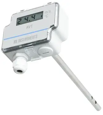
Thank you for choosing an HK Instruments CDT-MOD-2000 series carbon dioxide transmitter. The CDT-MOD-2000 series is intended for use in commercial environments in HVAC/R applications. The CDT-MOD-2000 series measures carbon dioxide (CO2), utilizing the industry-standard NDIR measurement principle, and temperature (T). Optional relative humidity (RH) measurement is also available in the same device. The CDT-MOD-2000 series devices are available with a large touchscreen display making the configuration of the device quick and easy. Configuration is also possible via the Modbus network.
The CDT-MOD-2000 series transmitters calibrate themselves automatically using ABCTM logic. The ABCTM logic requires that the space in which the transmitter is used needs to be unoccupied for four hours per day so that the indoor CO2 concentration drops to the outside level. CDT-MOD-2000-DC is a dual-channel model with a measuring channel and a reference channel that makes a continuous comparison and the necessary adjustment accordingly. CDT-MOD-2000-DC is also suitable for buildings that are continuously occupied.
WARNING
- READ THESE INSTRUCTIONS CAREFULLY BEFORE ATTEMPTING TO INSTALL, OPERATE OR SERVICE THIS DEVICE.
- Failure to observe safety information and comply with instructions can result in PERSONAL INJURY, DEATH, AND/OR PROPERTY DAMAGE.
- To avoid electrical shock or damage to equipment, disconnect power before installing or servicing and use only wiring with insulation rated for full device operating voltage.
- To avoid potential fire and/or explosion do not use in potentially flammable or explosive atmospheres.
- Retain these instructions for future reference.
- This product, when installed, will be part of an engineered system whose specifications and performance characteristics are not designed or controlled by HK Instruments. Review applications and national and local codes to assure that the installation will be functional and safe. Use only experienced and knowledgeable technicians to install this device.
APPLICATIONS
CDT-MOD-2000 series devices are commonly used to monitor:
- CO2 and humidity levels in offices, public spaces, meeting rooms, and classrooms
- CO2 levels of return air in ventilation systems
- incoming air and return air humidity levels in the ventilation system
- humidity in various industrial applications
- temperatures in the HVAC/R environment
- CDT-MOD-2000-DC series devices can also be used in applications where there is a constant source of carbon dioxide present (for example hospitals and greenhouses)
SPECIFICATIONS
Performance
Measurement ranges
- CO2: 400–2000 ppm
- Temperature: 0…50 °C
- Relative humidity: 0–100 %
Accuracy
- CO2: ±40 ppm + 2 % of reading, DC model: 75 ppm or 10 % of reading (whichever is greater)
- Temperature: <0.5 ºC
- Relative humidity: ±2…3 % at 0…50 °C and 10–90 % RH Total error band include accuracy, hysteresis, and temperature effect over 5…50 °C and 10–90% RH.
Technical Specifications
Media compatibility
- Dry air or non-aggressive gases
- Measuring units:
- ppm, °C, and % RH
Measuring element
- CO2: Non-dispersive infrared (NDIR)
- Temperature: Pt1000 (models without rH-measurement)
- Integrated (models with RH-measurement) Relative humidity: Thermoset polymer capacitive sensing element
Calibration
Automatic self-calibration ABC LogicTM or continuous comparison (DC)
Environment
- Operating temperature: 0…50 °C
- Storage temperature: -20…70 °C
- Humidity: 0 to 95 % RH, non condensing
Physical
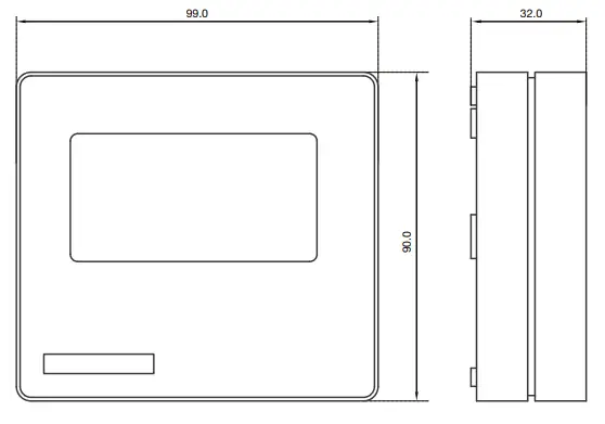
- Dimensions
- Case: 99 x 90 x 32 mm Weight:
- 150 g
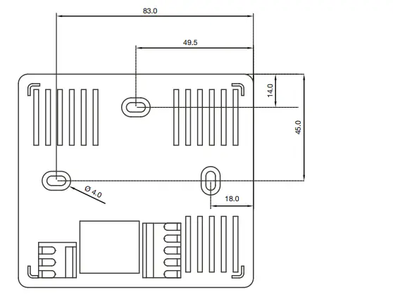
Mounting - 3 screw holes slotted, 3.8 mm Materials:
- Case: ABS
Protection standard - IP20
- Display (Optional) Touchscreen
- Size: 77.4 x 52.4 mm
Electrical connections
- Power supply
- 5-screw terminal block
- (24 V, GND)
- 0.2–1.5 mm2 (12–24 AWG)
- Relay out
- 3-screw terminal block
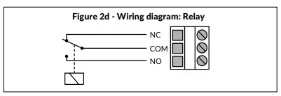
- (NC, COM, NO)
- 0.2–1.5 mm2 (12–24 AWG)
Electrical
- Input: 24 VAC or VDC, ±10 %
- Current consumption: max 90 mA (at 24 V) + 10 mA for each voltage output or 20 mA for each current output
- SPDT Relay, 250 VAC / 30 VDC / 6 A Adjustable switching point and hysteresis One analog output for selected media:
- 0/2*–10 VDC, Load R minimum 1 kΩ
- *(2–10 VDC display models only) or
- 4–20 mA, maximum load 500 Ω
Communication
Protocol
- MODBUS over Serial Line
- Transmission Mode: RTU
- Interface: RS485
- Byte format (11 bits) in RTU mode:
- Coding System: 8-bit binary Bits per Byte:
- 1 start bit
- 8 data bits, the least significant bit sent first
- 1 bit for parity
- 1 stop bit
Baud rate: selectable in configuration Modbus address: 1−247 addresses selectable in the configuration menu
Conformance
- Meets requirements for CE marking:
- EMC Directive 2014/35/EU
- RoHS Directive 2011/65/EU
- LVD Directive 2014/35/EU
- WEEE Directive 2012/19/EU
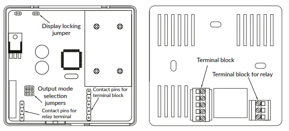
SCHEMATICS
DIMENSIONAL DRAWINGS
INSTALLATION
- Mount the device in the desired location (see step 1).
- Route the cables and connect the wires (see step 2).
- The device is now ready for configuration.
- Apply power only after the device is properly wired.
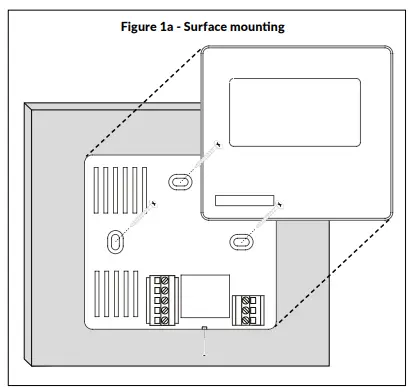
MOUNTING THE DEVICE
- Select a mounting location on the wall at 1.2–1.8 m (4–6 ft) above the floor and at least 50 cm (20 in) from the adjacent wall. Do not block device air vents from any direction and leave atleast 20 cm (8 in) gap to other devices. Locate the unit in an area with good ventilation and an average temperature, where it will be responsive to changes to the room conditions. The CDT-MOD should be mounted on a flat surface. Do not locate the CDT-MOD where it can be affected by:
- Direct sunlight
- Drafts or dead areas behind doors
- Radiant heat from appliances
- Concealed pipes or chimneys
- Outside walls or unheated/uncooled areas
- Use the device as a template and mark the screw holes.
- Mount the wall plate with screws.
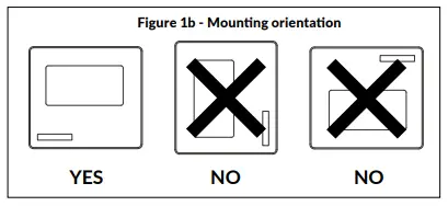
- Incorrect installation may cause a shift in temperature output
- Secure the lid with a locking screw, if the relay is connected to the mains power
WIRING DIAGRAMS
CAUTION!
- For CE compliance, a properly grounded shielding cable is required.
- Use copper wire only. Insulate or wire nut all unused leads.
- Supply a separate cable for the relay and signal out when using line voltage to power the relay.
- Any wiring may carry the full operating line voltage current based on field installation. The cover locking screw must be installed if the line voltage is supplied to the relay.
- Care should be used to avoid electrostatic discharge to the device.
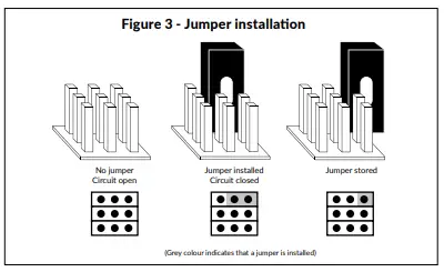
- This unit has configuration jumpers. You may need to reconfigure this device for your application.
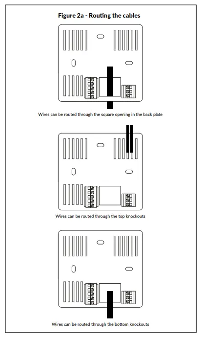
- Route the cables through the square opening in the backplate or for surface wiring select a knockout on the top or bottom of the wall plate, as shown in Figure 2a.
- Connect the wires as shown in Figures 2b and 2c.
WIRING DIAGRAMS CONTINUED
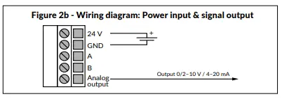
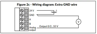
When using long connection wires it may be necessary to use a separate GND wire for voltage output current to prevent measurement distortion. The need for an extra GND wire depends on the cross-section and length of the used connection wires. If long and/or small cross-section wires are used, supply current and wire resistance may generate a voltage drop in the common GND wire resulting in a distorted output measurement.
CONFIGURATION
Configuration of the CDT-MOD-2000 series device consists of:
1) Configuring the jumpers (see step 4)
2) Configuration menu options. (Display versions only. See the user manual for further details)
Jumper settings
Configuration of the output modes
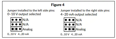
Select the output mode, current (4–20 mA) or voltage (0–10 V), by installing jumpers as shown in Figure 4.
To select 2–10 V output mode on a display version of the device: First, select 0–10 V output by jumper, then change the voltage (V) output from 0–10 V to 2–10 V via the configuration menu. Please see the user manual for more details.
Locking the display
Install the jumper to lock the display to prevent access to the configuration menu after installation is completed (see the schematics for the location of the pins).
MODBUS REGISTERS
Functions for Modbus communication:
| Function Code | Description |
| 01 | Read coil status |
| 02 | Read input status |
| 03 | Read holding registers |
| 04 | Read input registers |
| 05 | Force single coil |
| 06 | Preset single register |
| 07 | Read exception status |
| 15 | Force multiple coils |
| 16 | Preset multiple registers |
| 17 | Report slave ID |
Read input status
| Register | Parameter description | Data Type | Value | Range |
| 1×0001 | Relay status | Bit 0 | 0…1 | 0=Off – 1=On |
| 1×0002 | Relay trend | Bit 0 | 0…1 | 0=Increasing, 1=Decreasing |
| 1×0003 | Timer status | Bit 0 | 0…1 | 0=Off – 1=On |
Read input holding register
| Register | Parameter description | Data Type | Value | Range |
| 4×0001 | Parameter for P-controller | 16 bit | 0…3 | 0=CO2, 1=rH, 2=TE, 3=MAX |
| 4×0002 | CO2 hIgh limit | 16 bit | 500…2000 | 500…2000 ppm |
| 4×0003 | CO2 low limit | 16 bit | 0…1900 | 0…1900 ppm |
| 4×0004 | rH high limit | 16 bit | 100…1000 | 10.0…100.0 % |
| 4×0005 | rH low limit | 16 bit | 0…900 | 0.0…90.0 % |
| 4×0006 | TE high limit | 16 bit | 50…500 | 5.0. 50.0 °C |
| 4×0007 | TE low limit | 16 bit | 0…450 | 0.. 45.0 °C |
| 4×0008 | Parameter for relay | 16 bit | 0…3 | 0=CO2, 1=rH, 2=TE, (3=Off) |
| 4×0009 | CO2 relay on | 16 bit | 500…1950 | 500…1950 ppm |
| 4×0010 | CO2 relay off | 16 bit | 450…1900 | 450…1900 ppm |
| 4×0011 | rH relay on | 16 bit | 15…990 | 1.5…99.0 % |
| 4×0012 | rH relay off | 16 bit | 10…985 | 1.0…98.5 % |
| 4×0013 | TE relay on | 16 bit | 15…490 | 1.5. 49.0 °C |
| 4×0014 | TE relay off | 16 bit | 10…485 | 1.0.. 48.5 °C |
Read input register
| Register | Parameter description | Data Type | Value | Range |
| 3×0001 | Parameter for P-controller | 16 bit | 0…3 | 0=CO2, 1=rH, 2=TE, 3=MAX |
| 3×0002 | CO2 reading | 16 bit | 0…2000 | 0…2000 ppm |
| 3×0003 | rH reading | 16 bit | 0…1000 | 0,0…100.0 % |
| 3×0004 | Temp. reading | 16 bit | 0…500 | 0.0. 50.0 °C |
| 3×0005 | CO2 high limit | 16 bit | 500…2000 | 500…2000 ppm |
| 3×0006 | CO2 low limit | 16 bit | 0…1900 | 0…1900 ppm |
| 3×0007 | rH high limit | 16 bit | 100…1000 | 10.0…100.0 % |
| 3×0008 | rH low limit | 16 bit | 0…900 | 0.0…90.0 % |
| 3×0009 | TE high limit | 16 bit | 50…500 | 5.0. 50.0 °C |
| 3×0010 | TE low limit | 16 bit | 0…450 | 0.. 45.0 °C |
| 3×0011 | Parameter for relay | 16 bit | 0…3 | 0=CO2, 1=rH, 2=TE, (3=Off) |
| 3×0012 | CO2 relay on | 16 bit | 500…1950 | 500…1950 ppm |
| 3×0013 | CO2 relay off | 16 bit | 450…1900 | 450…1900 ppm |
| 3×0014 | rH relay on | 16 bit | 15…990 | 1.5…99.0 % |
| 3×0015 | rH relay off | 16 bit | 10…985 | 1.0…98,5 % |
| 3×0016 | TE relay on | 16 bit | 15…490 | 1.5. 49.0 °C |
| 3×0017 | TE relay off | 16 bit | 10…485 | 1.0.. 48.5 °C |
Write single coil
| Register | Parameter description | Data Type | Value | Range |
| 0x0001 | Relay trend | Bit 0 | 0…1 | 0=Increasing, 1=Decreasing |
| Register | Parameter description | Data Type | Value | Range |
| 4×0001 | Parameter for P-controller | 16 bit | 0…3 | 0=CO2, 1=rH, 2=TE, 3=MAX |
| 4×0002 | CO2 hIgh limit | 16 bit | 500…2000 | 500…2000 ppm |
| 4×0003 | CO2 low limit | 16 bit | 0…1900 | 0…1900 ppm |
| 4×0004 | rH high limit | 16 bit | 100…1000 | 10.0…100.0 % |
| 4×0005 | rH low limit | 16 bit | 0…900 | 0.0…90.0 % |
| 4×0006 | TE high limit | 16 bit | 50…500 | 5.0. 50.0 °C |
| 4×0007 | TE low limit | 16 bit | 0…450 | 0.. 45.0 °C |
| 4×0008 | Parameter for relay | 16 bit | 0…3 | 0=CO2, 1=rH, 2=TE, (3=Off) |
| 4×0009 | CO2 relay on | 16 bit | 500…1950 | 500…1950 ppm |
| 4×0010 | CO2 relay off | 16 bit | 450…1900 | 450…1900 ppm |
| 4×0011 | rH relay on | 16 bit | 15…990 | 1.5…99.0 % |
| 4×0012 | rH relay off | 16 bit | 10…985 | 1.0…98.5 % |
| 4×0013 | TE relay on | 16 bit | 15…490 | 1.5. 49.0 °C |
| 4×0014 | TE relay off | 16 bit | 10…485 | 1.0.. 48.5 °C |
Write multiple registers
| Register | Parameter description | Data Type | Value | Range |
| 4×0001 | Parameter for P-controller | 16 bit | 0…3 | 0=CO2, 1=rH, 2=TE, 3=MAX |
| 4×0002 | CO2 hIgh limit | 16 bit | 500…2000 | 500…2000 ppm |
| 4×0003 | CO2 low limit | 16 bit | 0…1900 | 0…1900 ppm |
| 4×0004 | rH high limit | 16 bit | 100…1000 | 10.0…100.0 % |
| 4×0005 | rH low limit | 16 bit | 0…900 | 0.0…90.0 % |
| 4×0006 | TE high limit | 16 bit | 50…500 | 5.0. 50.0 °C |
| 4×0007 | TE low limit | 16 bit | 0…450 | 0.. 45.0 °C |
| 4×0008 | Parameter for relay | 16 bit | 0…3 | 0=CO2, 1=rH, 2=TE, (3=Off) |
| 4×0009 | CO2 relay on | 16 bit | 500…1950 | 500…1950 ppm |
| 4×0010 | CO2 relay off | 16 bit | 450…1900 | 450…1900 ppm |
| 4×0011 | rH relay on | 16 bit | 15…990 | 1.5…99.0 % |
| 4×0012 | rH relay off | 16 bit | 10…985 | 1.0…98.5 % |
| 4×0013 | TE relay on | 16 bit | 15…490 | 1.5. 49.0 °C |
| 4×0014 | TE relay off | 16 bit | 10…485 | 1.0.. 48.5 °C |
RECYCLING/DISPOSAL
The parts left over from installation should be recycled according to your local instructions. Decommissioned devices should be taken to a recycling site that specializes in electronic waste.
WARRANTY POLICY
The seller is obligated to provide a warranty of five years for the delivered goods regarding material and manufacturing. The warranty period is considered to start on the delivery date of the product. If a defect in raw materials or a production flaw is found, the seller is obligated, when the product is sent to the seller without delay or before the expiration of the warranty, to amend the mistake at his/her discretion either by repairing the defective product or by delivering free of charge to the buyer a new flawless product and sending it to the buyer. Delivery costs for the repair under warranty will be paid by the buyer and the return costs by the seller. The warranty does not comprise damages caused by accident, lightening, flood or another natural phenomenon, normal wear and tear, improper or careless handling, abnormal use, overloading, improper storage, incorrect care or reconstruction, or changes and installation work not done by the seller or his/her authorized representative. The selection of materials for devices prone to corrosion is the buyer’s responsibility unless otherwise is legally agreed upon. Should the manufacturer alter the structure of the device, the seller is not obligated to make comparable changes to devices already purchased. Appealing for a warranty requires that the buyer has correctly fulfilled his/her duties arising from the delivery and stated in the contract. The seller will give a new warranty for goods that have been replaced or repaired within the warranty, however only to the expiration of the original product’s warranty time. The warranty includes the repair of a defective part or device, or if needed, a new part or device, but not installation or exchange costs. Under no circumstance is the seller liable for damages compensation for indirect damage.


