Shinko DSW-200-CO2 Indoor CO2 Sensor Instruction Manual
Preface
Thank you for purchasing our DSW-200-CO2, Indoor CO2 Sensor.
This manual contains instructions for installation and handling of the DSW-200-CO2. To ensure safe and correct use, thoroughly read and understand this manual before using this sensor. To prevent accidents arising from the misuse of this instrument, please ensure the operator receives this manual.
Notes
- This instrument should be used in accordance with the specifications described in the manual. If it is not used according to the specifications, it may malfunction or cause a fire.
- Be sure to follow all of the warnings, cautions and notices. If they are not observed, serious injury or malfunction may occur.
- The contents of this instruction manual are subject to change without notice.
- Care has been taken to ensure that the contents of this instruction manual are correct, but if there are any doubts, mistakes or questions, please inform our sales department.
- Any unauthorized transfer or copying of this document, in part or in whole, is prohibited.
- Shinko Technos Co., Ltd. is not liable for any damage or secondary damage(s) incurred as a result of using this product, including any indirect damage.
Safety Precautions
(Be sure to read these precautions before using our products.)
The safety precautions are classified into 2 categories: “Warning” and “Caution”.
Depending on the circumstances, procedures indicated by Caution may result in serious consequences, so be sure to follow the directions for usage.
 Warning
Procedures which may lead to dangerous conditions and cause death or serious injury, if not carried out properly.
Caution
Procedures which may lead to dangerous conditions and cause superficial to medium injury or physical damage or may degrade or damage the product, if not carried out properly.
Warning
- To prevent an electrical shock or fire, only Shinko or other qualified service personnel may handle the inner assembly.
- To prevent an electrical shock, fire or damage to the instrument, parts replacement may only be undertaken by Shinko or other qualified service personnel.
SAFETY PRECAUTIONS
- To ensure safe and correct use, thoroughly read and understand this manual before using this instrument.
- This instrument is intended to be used for general equipment. Verify correct usage after purpose-of-use consultation with our agency or main office. (Never use this instrument for medical purposes with which human lives are involved.)
- External protection devices must be installed, as malfunction of this product could result in serious damage to the system or injury to personnel. Proper periodic maintenance is also required.
- This instrument must be used under the conditions and environment described in this manual. Shinko Technos Co., Ltd. does not accept liability for any injury, loss of life or damage occurring due to the instrument being used under conditions not otherwise stated in this manual.
Caution with Respect to Export Trade Control Ordinance
To avoid this instrument from being used as a component in, or as being utilized in the manufacture of weapons of mass destruction (i.e. military applications, military equipment, etc.), please investigate the
end users and the final use of this instrument. In the case of resale, ensure that this instrument is not illegally exported.
1. Model
1.1 Model
| Model | DSW-200 | – | – | – | ||
| Measuring object | CO2 | CO2 concentration | ||||
| Measurement range | 1 | 360 to 2000 ppm (with Sensor Correction Function) | ||||
| 2 | 360 to 5000 ppm (with Sensor Correction Function) | |||||
| 3 | 0 to 2000 ppm | |||||
| 4 | 0 to 5000 ppm | |||||
|
Output spec | 1 | 4 to 20 mA DC | ||||
| 2 | 0 to 20 mA DC | |||||
| 3 | 1 to 5 V DC | |||||
| 4 | 0 to 5 V DC | |||||
| 5 | 0 to 1 V DC | |||||
| Moisture-proof coating | 0 | Not needed | ||||
| 1 | Needed | |||||
1.2 How to Read the Model Label
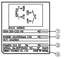
Model label is attached to the inside of the case.
- Model
- Measurement range, Output
- Power supply voltage, Power consumption
- Serial number
2. Mounting
Caution
Turn the power supply to the instrument OFF before wiring, otherwise it may result in a malfunction.
Installation site should be examined, giving careful consideration to the following conditions. Please note that this product is designed for indoor use only.
[This instrument is intended to be used under the following environmental conditions.]
- Mount on a wall about 1.5 m high above the floor, in average temperature and humidity
- 0.1 to 0.15 m/s of ambient wind velocity
- Sufficient space for maintenance in front of the sensor
- Install in a location where heat does not stay on such as near OA equipment.
- No furniture, fixtures or doors to block air flow
- No draft, downdraft, or cool/warm air from water pipes/ducts
- A minimum of dust, and an absence of corrosive gases
- No flammable, explosive gases
- Few mechanical vibrations or shocks
- No exposure to direct sunlight, an ambient temperature of 0 to 50 (32 to 122 ) without rapid change, and no icing
- An ambient non-condensing humidity of 5 to 95 %RH
- An absence of chlorinated and sulfidizing gases
- No water, oil, chemicals or the vapors of these substances can come into direct contact with the sensor.
Maintenance
- Check and clean the main unit cover thoroughly once a year.
- Change the sensor when no output occurs.
- For products without the Sensor Correction Function, a maximum of ±300 ppm/year of sensitivity decrease may occur in continuous power-on status.
Therefore, a periodic calibration and/or replacement of the sensor are/is recommended.
(1) Fixing the Mounting Plate
Screw either (A) or (B), and fix the Mounting Plate to the outlet box, via outlet box cover located inside the wall.
For screws, use M4 screw (2 pieces) and spring washer provided.
(2) Wiring
Connect the main unit lead wire to
the wire from the wall side.
(3) Mounting Main Unit
Screw 4 places (C) as indicated by the dotted lines, and fix the sensor main unit to the Mounting Plate. For screws, use M3 screw (4 pieces) provided.
(4) Fitting Main Unit Cover Insert the main unit cover protrusion (2 places) into the cover mounting holes (2 places) located on the
upper part of the sensor main unit, then fit the cover to the sensor main unit.
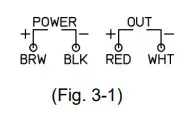
3. Wiring
| Lead Wire Color | Lead Wire Type | |
| BRW: Brown | + | Power supply |
| BLK: Black | – | |
| RED: Red | + | Output |
| WHT: White | – | |
4. Operation Checking
| Sensor Status | Output |
| Initial operation | Output low limit value |
| Sensor is operating normally. | Output low limit to Output high limit |
| Sensor is out of order. | Output high limit value +10 %FS |
Sensor status and output are described.
5. Specifications
| Measurement Range | 360 to 2000 ppm, 360 to 5000 ppm, 0 to 2000 ppm, 0 to 5000 ppm (must be specified) | ||
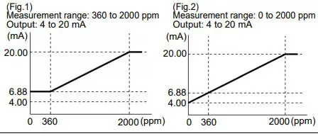
| Output | 4 to 20 mA DC, 0 to 20 mA DC, 1 to 5V DC, 0 to 5V DC, 0 to 1V DC (must be specified) [Output of CO2 Sensor] (Fig.1) (Fig.2) For each range of CO2 con- Measurement range: 360 to 2000 ppm Measurement range: 0 to 2000 ppm Output: 4 to 20 mA Output: 4 to 20 mA centrations, linearly outputs centration. However, if the “360 to 2000 ppm” or “360 to 5000 ppm” range is selected, and if the measured value is lower than 360 ppm, the value corresponding to 360 ppm will be output. | ||
| Power Supply Voltage | 24 V DC 10% | ||
| Measurement Method | Non-dispersive infrared (NDIR) | ||
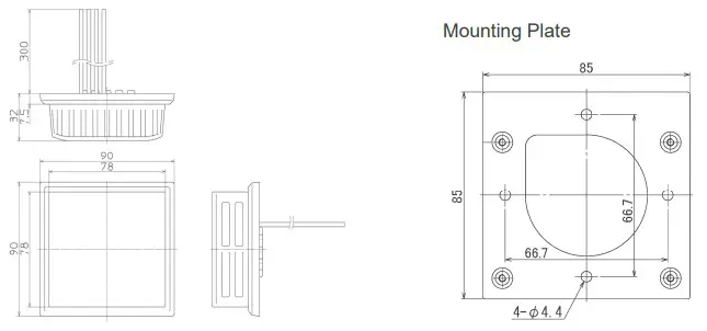
| Mounting | To the outlet box (inside wall), via outlet box cover: Mounting dimension: 66.7 mm (JIS C8340: 1999) (JIS: Japan Industrial Standards) | ||
| Material | Flame-resistant PC resin, Color: White | ||
| Wiring | Lead wire: 300 mm Cross-section area: 0.5 mm2 See “3. Wiring” for details. | ||
| Performance | Accuracy | (50 ppm + 3% of measured value). However, 300 ppm or less: 100 ppm Accuracy described here is the factory default. | |
| Warm-up period | 30 minutes | ||
| Response characteristics | Within 120 seconds | ||
 corresponding to CO2 con-
| Atmospheric pressure | The atmospheric pressure can be corrected by setting the altitude of the installation site with the Rotary Switch. | |||
| Setting range | 0 to 9900 m above sea level, however, for 2500 m or more of altitude setting, 2550 m is the maximum correction value. | |||
| Setting unit | 100 m | |||
| Output spec | Output signal | Outputs linearly corresponding to CO2 concentration of each range. | ||
| Resolution | 0.05 %FS max. | |||
| Allowable load resistance | Output Range | Allowable Load Resistance | ||
| 4 to 20 mA, 0 to 20 mA | 550 max. | |||
| 1 to 5 V, 0 to 5 V | 5 k minimum | |||
| 0 to 1 V | 1 k minimum | |||
| Sensor Correction | One cycle is equivalent to 45 days, and if the measured value drops below 400 ppm in the current cycle, the lowest value in the current cycle will become 400 ppm in the next cycle. and the difference between the lowest value and 400 ppm will be added to all other measured values in the next cycle. (Available for the “360 to 2000 ppm” and “360 to 5000 ppm” ranges.) If the power supply is turned OFF, the number of days in the cycle will be reset. | |||
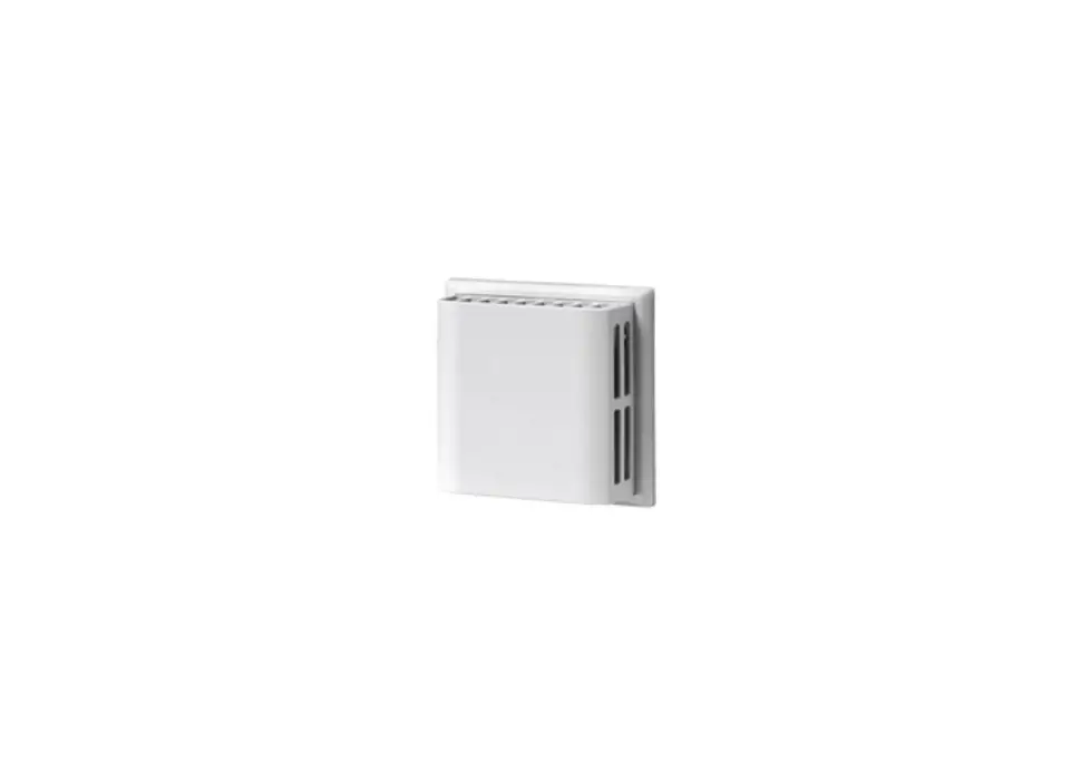
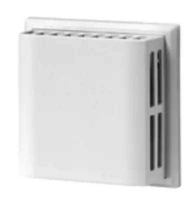
| External Dimensions | W90 x H90 x D32 mm (excluding lead wire)
Mounting Plate
| |||
| Power Consumption | Approx. 3 W | |||
| Operating Environment | Temperature: 0 to 50 Humidity: 0 to 95 %RH (Non-condensing) | |||
| Storage Environment | Temperature: -30 to 70 Humidity: 0 to 95 %RH (Non-condensing) | |||
| Weight | Approx. 100 g | |||
| Insulation Resistance | Between Case – Output: 500 M minimum, at 500 V DC | |||
| Dielectric Strength | Between Case – Output: 1.5 kV for 1 minute, 3 mA max. | |||
| Moisture-Proof Coating | Printed-circuit board inside the main unit (excluding sensor) | |||
| Accessories | Mounting Plate, Mounting Plate screw: M4 x 8 (2 pieces), Spring washer: 2 pieces, Sensor main unit mounting screw: M3 x 4 (4 pieces), Instruction manual: 1 copy | |||
| Environmental Spec | RoHS directive compliant | |||
Inquiries:
For any inquiries about this instrument, please contact our agency or the vendor where you purchased the unit after checking the model and serial number. Please let us know the details of the malfunction, or discrepancy, and the operating conditions


