
Inhand RS-CO2 WS-N01 CO2 Temperature and Humidity Transmitter
Product Introduction
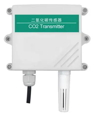
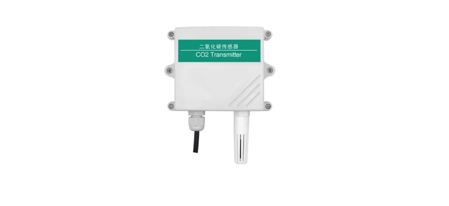
Product summary
The transmitter is widely used in communication room, warehouse buildings and automatic temperature and humidity monitoring needs of the place, the sensor input power, temperature measurement unit, the signal output is completely isolated from three parts. Safe, reliable, beautiful appearance, easy installation.
Function feature
This product uses high sensitivity gas detection probe, signal stability, high precision. With a wide measuring range, good linearity, easy to use, easy to install, transmission distance and so on.
Main technology parameter
- Power supply: 10 ~ 30V DC
- average current: <85mA
- CO2 Measurement range: 0 ~ 5000ppm (can be customized)
- Accuracy of CO2: ± (40ppm + 3% F · S) (25 ℃)
- Temperature measurement range: -40 ℃ ~ 80 ℃
- Humidity measurement range: 0 ~ 100% RH
- Stability: <2% F · S
- Data Update Time: 2s
- Temperature effects: comes with temperature Compensation
- Temperature accuracy: ± 0.5 ℃
- Humidity accuracy: ± 3% RH
- Nonlinearity: <1% F · S
- Warm-up time: 2min (available), 10min (maximum precision)
- Output signal: 485, relay (optional)
System frame diagram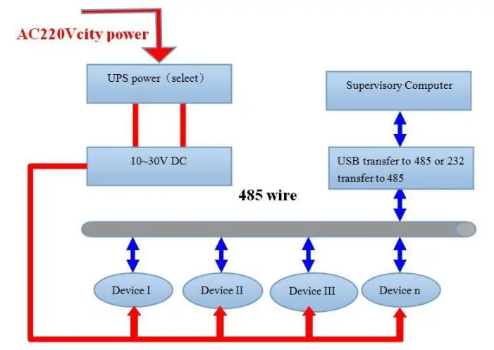
Device Installation Instruction
Check before the device installation
Device list:
- One transmitter equipment
- Certificate, warranty card, and after sales service card and so on
- one 12V/2A waterproof power (select)
- USB transfer to 485 (select)
Joggle instruction
Range 10V-30V of wide voltage is available in power input, the A wire and B wire cannot be connected contrary when connecting to 485 signals, and the address among several devices on the total wire cannot be conflicted.
| Line color | Description | |
| power | brown | Power supply is (10 ~ 30V DC) |
| black | Power supply negative | |
| Communication | yellow | 485-A |
| blue | 485-B |
485 field wiring instructions
Multiple 485 models of equipment access the same bus, the field wiring has certain requirements, please refer to the specific parameters Test data packets in the “485 device field wiring manual.”
Configuration Software Installation and Application
Software selection
Opening the datagram, and choosing “test software” —- “485 parameter setting software” and finding out and opening it.
Parameter setting
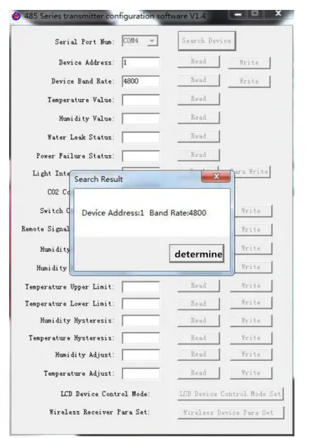
- select the right COM port (“my computer——properties——deceive manager——Port”) and check the COM port from the Port, the name of several different kinds of 485 transmitter drive

- connect with only one device and be powered, and click “test the baud rate” of the software to test the device baud rate and address, the default baud rate is 4800bit/s and default address is 0x01
- Change the address and baud rate based on the application requirement, and meanwhile the current situation of the device function can be checked
- if the test is not success, please check the device wring and 485 drive installation situations again


Communication Agreement
Communication basic parameter
| Stop Bit | 1bit |
| Error check | CRC(Redundant cyclic codes) |
| Baud Rat e | 2400bit/s, 4800bit/s, 9600 bit/s options, the factory default 4800bit/s |
The concept of data frame format
Apply Modbus-RTU communication rules, the format below:
- Initial structure ≥4 byte time
- Address code = 1 byte
- Function code = 1 byte
- Data area = N byte
- Incorrect revision = 16 byte CRC code
- Ending structure ≥4 byte time
- Address code:the address of the transmitter,and will be the only (factory default 0x01) in the communication net. Function code : the order function orders from
- host computer; this transmitter only uses function code 0x03(reading register date).
- Data area:data area is the specific communication data, attention16bits data high byte in front!
- CRC codetwo-byte revision code.
- Main computer enquires frame structure
| Addr ess Code | Functi on Code | Register Origin Address | Register Length | Revision Code in Low Position | Revision Code in High Position |
| 1byte | 1byte | 2bytes | 2bytes | 1byte | 1byte |
Accessorial computer replying frame structure:
| Addres s Code | Func tion Code | Effectiv e ness Byte NO. | Data Area One | Data Are a Two | Data Area N | Revision Code |
| 1byte | 1byte | 1byte | 2bytes | 2bytes | 2bytes | 2bytes |
Register address
| Register | PLC or | Content | Operati | Scope and definition |
| Address | Configuration Address | ion | of the definition | |
| 0000 H | 40001 | Temperature | Read only | 0~1000 |
| 0001 H | 40002 | humidity | Read only | -400~1000 |
| 0002 H | 40003 | CO2 concentration | Read and write | 0~5000 |
| 0030 H | 40049 | Temperature upper limit alarm value | Read and write | -400~1000 |
| 0031 H | 40050 | Temperature lower limit alarm value | Read and write | -400~1000 |
| 0032 H | 40051 | Temperature alarm back to the difference | Read and write | 0~1000 |
| 0033 H | 40052 | Temperature calibration value | Read and write | -400~1000 |
| 0034 H | 40053 | The temperature relay is enabled | Read and write | 1 is enabled, 0 is disabled |
| 0035 H | 40054 | High humidity alarm value | Read and write | 0~1000 |
| 0036 H | 40055 | Low alarm value of humidity | Read and write | 0~1000 |
| 0037 H | 40056 | Humidity alarm back to the difference | Read and write | 0~1000 |
| 0038 H | 40057 | Humidity calibration value | Read and write | -400~1000 |
| 0039 H | 40058 | The humidity relay is | Read and | 1 is enabled, 0 is disabled |
| enabled | write | |||
| 003a H | 40059 | CO2 high alarm value | Read and write | 0~5000 |
| 003b H | 40060 | CO2 lower limit alarm value | Read and write | 0~5000 |
| 003c H | 40061 | CO2 alarm back to the difference | Read and write | 0~5000 |
| 003d H | 40062 | CO2 calibration value | Read and write | -2000~2000 |
| 003e H | 40063 | CO2 relay is enabled | Read and write | 1 is enabled, 0 is disabled |
| 0040 H | 40065 | Relay Status | Read and write | 1 for the suction, 0 for the disconnect |
Communication agreement example and explaining
For example: Read the CO2 value at device address 0x01 enquiry frame:
| Address Code | Function Code | Start Address | Data Length | Check Dig it Low | Check Digit High |
| 0x01 | 0x03 | 0x00 0x0 2 | 0x00 0x01 | 0x25 | 0xCA |
Replication frame: (For example, read CO2 to 3000 ppm)
| Address Code | Functio n Code | Returns the number of valid bytes | Light intensity value | Check digit low | Check digit high |
| 0x01 | 0x03 | 0x02 | 0x0B 0xB8 | 0xBF | 0x06 |
CO2: BB8 H (Hex) = 3000 => CO2 = 3000 ppm
For example:Read the CO2 with Temperature and humidity value at device address 0x01
enquiry frame:
| Address Code | Function Code | Start Address | Data Length | Check Di git | Check Digit High |
| Low | |||||
| 0x01 | 0x03 | 0x00 0x0 0 | 0x00 0x0 3 | 0x05 | 0xCB |
Replication frame: (when reading temperature is -7.5℃,humidity is 35.9%RH, CO2 is 3000ppm)
| Address Code | Function Code | Valid bytes | Humidity value | Temperature value | CO2 value | Check digit low | Check digit high |
| 0x01 | 0x03 | 0x06 | 0x01 0x67 | 0xFF 0xB5 | 0x0B 0xB8 | 0x33 | 0xDC |
Common Problem and Solution
Device cannot be connected with PLC or computer
Reasons possible:
- Several COM ports in the computer, the port be chosen is incorrect.
- The device address is wrong, or some device addresses are repeat.(all factory defaults are ).
- Baud rate, revision mode, data position and stop position are wrong.
- The main computer and polling interval is too small and time waiting for replying is too short, and all need to set over 200ms.
- The 485 general wire is broken or the A wire and B wire are connected in the wrong side.
- To many devices or too long wires, the power needs to be chosen nearby, add 485 intensifiers, and add 120Ω terminal electric resistance.
- The driver of USB transfer to 485is not installed or damaged.
- The device is broken.
Document History
- V1.0: Document building.
- V1.1: add a variety of card rail shell.
- V1.2: increase wiring rules and solutions to common problems.
Shell Size
The overall size: 110 × 85 × 44mm