![]() AQS-KAM-xx, AQS 71-KAM-T, AQS-KAM-RH-V
AQS-KAM-xx, AQS 71-KAM-T, AQS-KAM-RH-V
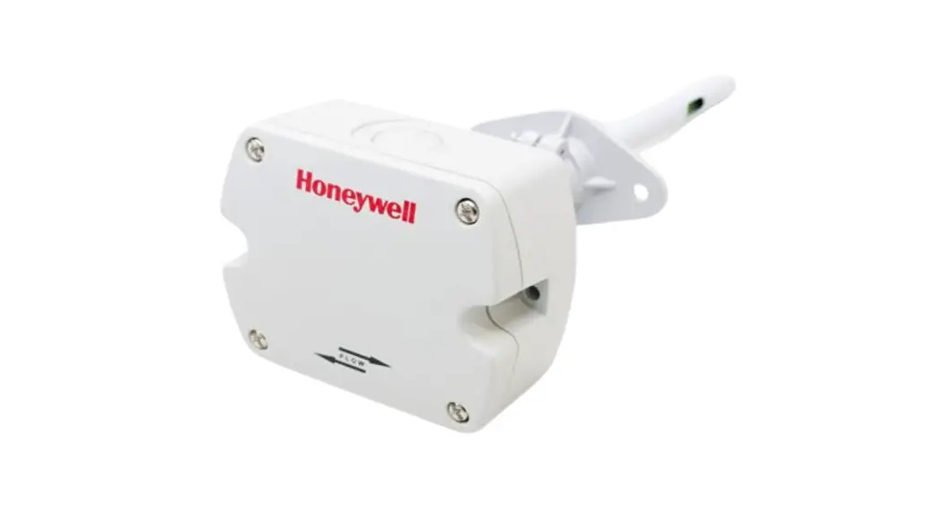
CO2 TEMPERATURE HUMIDITY TRANSMITTERS
Instruction Manual 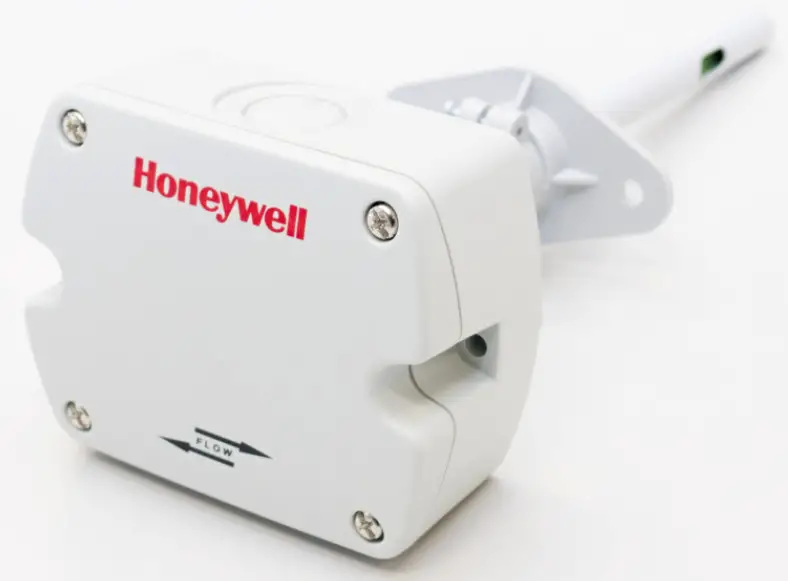
GENERAL
The AQS Temperature Transmitters set new standards in CO2 measurements in HVAC applications. Operation is based on the infrared principle. A calibration-free procedure compensates for aging of the infrared source and ensures outstanding long-term stability. The AQS provide 0…10 V analog output for CO2 and temperature and are designed for HVAC applications (contact Honeywell for special applications). They are suitable for direct wiring with universal and voltagecontrolled inputs. Additionally, the AQS-KAM-xx Temperature Transmitters feature a built-in passive temperature sensor. The AQS-KAM-RH-V Temperature Sensor is equipped with a relative humidity sensor. See also following table.
Table 1. List of devices
| OS number | CO2 + temp. output | temp. output (passive) | rel. humidity output |
| AQS-KAM-00 | 0…10 V | Pt1000 | — |
| AQS-KAM-01 | Ni1000 | — | |
| AQS-KAM-10 | NTC101Ω | — | |
| AQS-KAM-20 | NTC20kΩ | — | |
| AQS 71-KAM-T | — | ||
| AQS-KAM-RH-V | 0…10 V |
NOTE: Avoid strong mechanical stress and improper handling. The cable gland and housing cover must be screwed tightly against gas penetration, to avoid incorrect measurements.
PRODUCT DATA & INSTALLATION INSTRUCTIONS
FEATURES
- Calibration-free technology
- Outstanding long-term stability
- Maintenance free
- universal mounting flange
SPECIFICATION
| Power supply | 24 Vac, ±20% (SELV) 15…35 Vdc |
| Power consumption | 0.6 W |
| Max. current consumption | 0.35 A (0.3 sec / 15 sec) |
Ambient Limits
| Operating temperature | -20…+60 °C (-4…+140 °F) |
| Transport and storage | -20…+60 °C (-4…+140 °F) |
| Humidity | 0…95% rh, non-condensing |
Safety
| Protection class | III as per EN 60730-1 |
| Protection standard | Housing IP65 as per EN60529 Probe IP20 |
| Housing material | Flame retardant V0 as per UL94 |
| Housing | plastic (PC) |
| Dimensions | see Fig. 1 on page 3 |
| Mounting | duct, M16x1,5 cable inlet |
CO2 Sensor
| Output signal | 0…10 V |
| Output current | -1 mA < IL < 1 mA |
| Output scaling | 0…10 V = 0…2000 ppm CO2 |
| Accuracy (CO2 at | 0…2000 ppm < ± (50 ppm |
| 25°C [77°F], 1013 mbar) | +2% of measured value) |
| Temperature stability: | typ. ± (1 + CO2 conc. [ppm] / 1000) ppm / K (-20 … +45 °C) |
| Response time | t63 < 100 sec at 3 m/s |
| Warm-up time | < 5 min |
Temperature
| Output signal | 0…10 V |
| Output Current | -1 mA < IL < 1 mA |
| Output scaling | 0…10 V = 0…50 °C |
| Accuracy (20 °C [68 °F]) | ± 0.3 K |
| Response time | t63 < 50 sec. at 3 m/s |
| AQS-KAM-RH-V | t63 < 60 sec. at 3 m/s |
Table 2. Troubleshooting
| Error | Possible cause | Remedies |
| Unrealistic results | Skewed installation | Air inlet and probe tip must be perpendicular to air flow. |
| Low air velocity | Air velocity must be > 1 m/sec (200 ft/min). | |
| Housing not tight | Seal cover and gland tightly. | |
| Long response time | Contamination of sensor or probe | Check sensor and probe for soiling and clean, as necessary. |
Passive Temp. Sensors (AQS-KAM-xx)
| Output | 2-wire |
| Wire resistance (typ.) | 0.4 Ω (terminal-sensor) |
NTC10kΩ
| Nominal value | 10kΩ ±0.5% at 25 °C |
| Accuracy | ±0.2 °C at 25 °C |
| Response time (typ.) | t63 < 120 s at 3 m/s air velocity |
| Sensitivity (typ.) | -440 Ω / K at 25 °C (non-linear) |
NTC20kΩ
| Nominal value | 20kΩ ±0.5% at 25 °C |
| Accuracy | ±0.2 °C at 25 °C |
| Characteristic | NTC20kΩ (see EN0B-0476GE51) |
| Response time (typ.) | t63 < 120 s at 3 m/s air velocity |
| Sensitivity (typ.) | ≈ -934.5 Ω / K at 25 °C (non-linear) |
Ni1000
| Nominal value | 1000 W at 0 °C |
| Accuracy | ±0.4 °C at 0 °C |
| Characteristic | DIN 43760 |
| Sensitivity (typ.) | ≈ 6.18 W / K |
Pt1000
| Nominal value | 1000 W at 0 °C |
| Accuracy (IEC751 Cl. B) | 0.3 + 0.005*│t│ at 0 °C |
| Characteristic | see EN0B-0476GE51 |
| Sensitivity (typ.) | ≈ 3.85 W / K |
Relative humidity (AQS-KAM-RH-V)
| Working range | 0…95% RH, non-condensing |
| Output | 0…10 V prop. to 0…100% RH |
| Accuracy at 20 °C | typ. ±2% RH, max. ±3% RH in range of 20…80% RH |
NOTE: Temperature / relative humidity / CO2 accuracy may differ, depending on various environmental conditions (e.g., air velocity or temperature difference between the air temperature and the ambient temperature).
WIRING
| wiring run | maximum length |
| sensor to controller | 200 m (660 ft) |
NOTE: Installation of the sensor near high EMI-emitting devices may lead to faulty measurements.
Use shielded wiring in areas with high EMI.
Keep 15 cm (5.9’’) min. distance between sensor lines and 230 Vac power lines.
Use two transformers: one for sensors and actuators and one for the controller.
DIMENSIONS
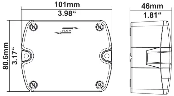 Fig. 1. Housing dimensions (mm)
MOUNTING
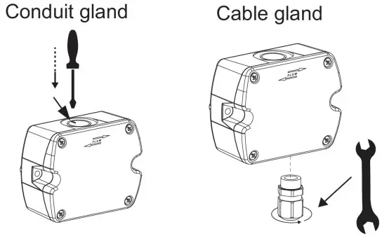 Screw with torque of 1.5 Nm for break-through. Recommended tightening torque: 3.5 Nm.
Fig. 2. Assembly of conduit / cable gland 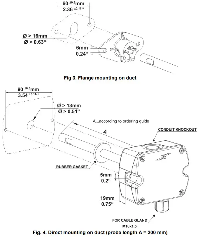
WIRING 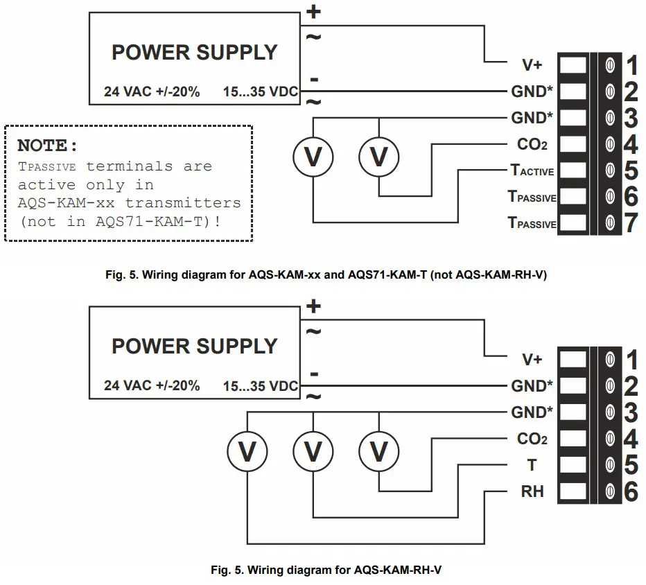
*IMPORTANT
For failure-free operation and performance according to specifications, it is essential that the supply GND and the measurement GND be wired separately!
Manufactured for and on behalf of the Environmental & Energy Solutions Division of Honeywell Technologies Sàrl, Rolle, Z.A. La Pièce 16, Switzerland by its Authorized Representative:
Home and Building Technologies
Honeywell GmbH
Böblinger Strasse 17
71101 Schönaich, Germany
Phone +49 (0) 7031 637 01
Fax +49 (0) 7031 637 740
http://ecc.emea.honeywell.com
EN1B-0377GE51 R0518F
![]() Subject to change without notice
Subject to change without notice
Strandvejen 42 • Saksild • 8300 Odder 86 62 63 64
• www.automatikcentret.dk
[email protected]![]()


