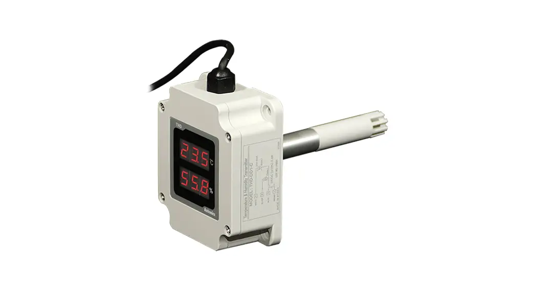
![]() THD Series Temperature and Humidity Sensor
THD Series Temperature and Humidity Sensor
Temperature / Humidity Sensor
THD Series
INSTRUCTION MANUAL
TCD220002AB
THD Series Temperature and Humidity Sensor
Thank you for choosing our Autonics product. Read and understand the instruction manual and manual thoroughly before using the product.
For your safety, read and follow the below safety considerations before using. For your safety, read and follow the considerations written in the instruction manual, other manuals and Autonics website.
Keep this instruction manual in a place where you can find easily.
The specifications, dimensions, etc. are subject to change without notice for product improvement. Some models may be discontinued without notice. Follow Autonics website for the latest information.
Safety Considerations
- Observe all `Safety Considerations’ for safe and proper operation to avoid hazards.
- symbol indicates caution due to special circumstances in which hazards may occur.
![]() Warning Failure to follow instructions may result in serious injury or death.
Warning Failure to follow instructions may result in serious injury or death.
- Fail-safe device must be installed when using the unit with machinery that may cause serious injury or substantial economic loss.(e.g. nuclear power control, medical equipment, ships, vehicles, railways, aircraft, combustion apparatus, safety equipment, crime/disaster prevention devices, etc.)
Failure to follow this instruction may result in personal injury, economic loss or fire. - Do not use the unit in the place where flammable/explosive/corrosive gas, high humidity, direct sunlight, radiant heat, vibration, impact or salinity may be present.
Failure to follow this instruction may result in explosion or fire. - Do not connect, repair, or inspect the unit while connected to a power source.
Failure to follow this instruction may result in fire. - Check `Connections’ before wiring.
Failure to follow this instruction may result in fire. - Do not disassemble or modify the unit.
Failure to follow this instruction may result in fire.
![]() Caution Failure to follow instructions may result in injury or product damage.
Caution Failure to follow instructions may result in injury or product damage.
- Use the unit within the rated specifications.
Failure to follow this instruction may result in fire or shortening the life cycle of the product. - Use a dry cloth to clean the unit, and do not use water or organic solvent.
Failure to follow this instruction may result in fire. - Keep the product away from metal chip, dust, and wire residue which flow into the unit.
Failure to follow this instruction may result in fire or product damage.
Cautions during Use
- Follow instructions in `Cautions during Use’. Otherwise, it may cause unexpected accidents.
- Keep away from high voltage lines or power lines to prevent inductive noise. In case installing power line and input signal line closely, use line filter or varistor at power line and shielded wire at input signal line. Do not use near the equipment which generates strong magnetic force or high frequency noise.
- Install a power switch or circuit breaker in the easily accessible place for supplying or disconnecting the power.
- 24VDC power supply should be insulated and limited voltage/current or Class 2, SELV power supply device.
- Do not overlapping communication line and power line. Use twisted pair wire for communication line and connect ferrite bead at each end of line to reduce the effect of external noise.
- Do not touch THD-W/D sensor part at the bottom of the sensor pole by hands. It may cause malfunction.
- THD-R must be installed on the wall. It may cause malfunction.
- Make a required space around the unit for radiation of heat. For accurate temperature measurement, warm up the unit over 20 min after turning on the power.
- Make sure that power supply voltage reaches to the rated voltage within 2 sec after supplying power
- Do not wire to terminals which are not used.
- This unit may be used in the following environments.
– Indoors (in the environment condition rated in `Specifications’)
– Altitude max. 2,000 m
– Pollution degree 2
– Installation category II
Ordering Information
This is only for reference.
For selecting the specified model, follow the Autonics website.

- Mounting type
R: Room type (for indoor)
D: Duct mounting type
W: Wall mounting type - Display
No mark: Non-display type
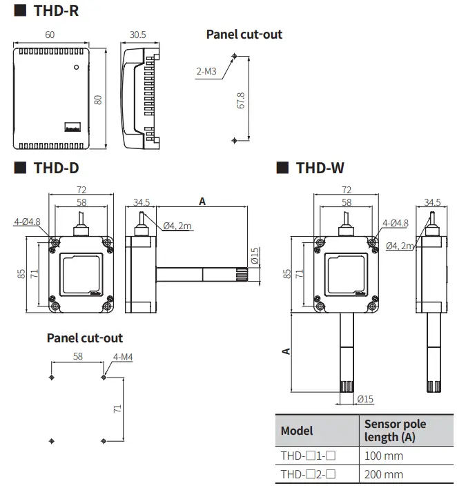
D: Display type - Sensor pole length
No mark: Built-in type
1: 100 mm
2: 200 mm - Output
| Temperature | Humidity | |
| C | Current output | |
| V | Voltage output | |
| T | RS485 communication output | |
| PT | DPt1000 resistance value | – |
| PT/C | DPt100 resistance value | Current output |
Product Components
- Product
- Instruction manual
- Bracket (THD-W / D model)
Software
Download the installation file and the manuals from the Autonics website.
■ DAQMaster
DAQMaster is comprehensive device management program. It is available for parameter setting, monitoring.
Dimensions
- Unit: mm, For the detailed drawings, follow the Autonics website.
Bracket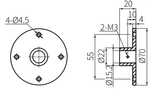
Connections
• Check the terminal connection diagram and be careful with connecting the power. 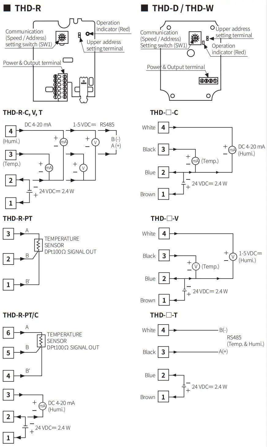
Case Detachment
When setting communication, turn off the power, remove the case cover, and operate the communication setting switch to set the communication address and speed. Refer to ‘RS485 Communication’ for the details.
■ THD-R
• Unfasten the bolt on the bottom of the product, separate the case from it.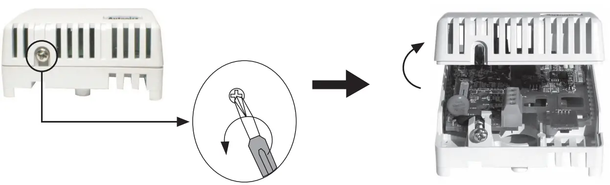 ■ THD-D/THD-W
• Unfasten 4 bolts on the top of the product, separate the case cover from it.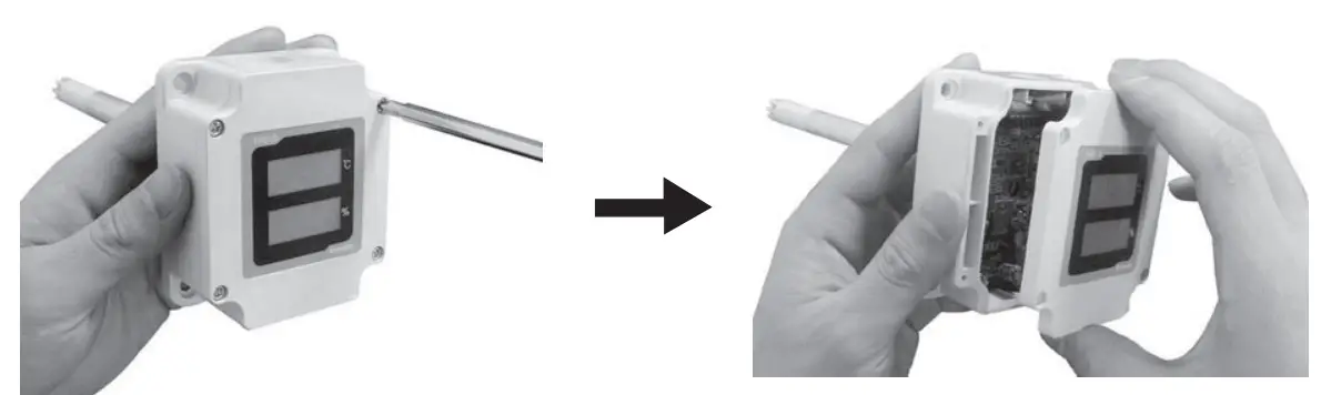
Errors
| Display part (Temp. / Humi) | Description | Troubleshooting |
| Light is ON when malfunction of sensor module. | Contact our A/S center. | |
| Light is ON when PV is higher than measuring range. | When input is within the measuring range, this display disappears. | |
| Light is ON when PV is lower than measuring range. |
Specifications
| Model | THD-R-PT |
| Sensor type | Temperature sensor |
| Display type | Non-display type |
| Temp. measuring range | -19.9 to 60.0 °C |
| Temp. accuracy | < +0 8 °C |
| Temp. output | DPt100 Q resistance value (TCR: 3850 ppm/°C) |
| Protection structure | IP10 (IEC standards) |
| Ambient temperature | -20 to 60 °C, Storage: -20 to 60 °C (rated at no freezing or condensation) |
| Approval |
| Model | THD-R-PT/C | THD-R-C THD-R-V THD-R-T | THD-DH-❑-❑………………………………..THD-WL-❑-❑ THD-WD❑-❑………………………………….THD-DD❑-❑ | |
| Power supply | 24 VDC= ±10 % | |||
| Power consumption | 2.4W | |||
| Sensor type | Temperature/Humidity Sensor | |||
| Sensor response time | 10 sec | |||
| Display type | Non-display type | 7 seg. LED display | ||
| Display digit | Each 3 digits for temp. / humi. | |||
| Temp. measuring range | -19.9 to 60.0 °C | |||
| Humi. measuring range | 0.0 to 99.9 %RH (THD-R is required to attend for using over 90 %RH) | |||
| Temp. accuracy | ± 1.0 °C (at room temp.) | |||
| Humi. accuracy | ± 3 %RH (30 to 70 %RH, at room temp.) ± 4 %RH (10 to 90 %RH) | Typ. (10 ± 2to 90 WO %RH RH, at room temp.) ± 2.5 WoRH | ||
| Temp. output | DPt100 0 resistance value (TCR: 3850 pp m/°C) | DC 4-20 mA (allowable impedance: 600 0), 1-5 VDC=, RS485 Communication (Modbus RTU) | ||
| Humi. output | DC 4-20 mA (allowable impedance: < 600 0) | |||
| Resolution | 1/1000 | |||
| Sampling period | 0.5 sec | |||
| Insulation resistance | 100 M0 (500 VDC= megger) | |||
| Dielectric strength | 500 VAC— 50/60 Hz for 1 min | |||
| Noise immunity | ±0.3 kV the square wave noise (pulse width: 1 ps) by the noise simulator | |||
| Vibration | 0.75 mm amplitude at frequency of 10 to 55 Hz (for 1 min) in each X, Y, Z direction for 1 hour | |||
| Vibration (Malfunction) | 0.5 mm amplitude at frequency of 10 to 55Hz (for 1 min) in each X, Y, Z direction for 1 hour | |||
| Shock | 300 m/s’ (——- 30 G) in each X, Y, Z direction for 3 times | |||
| Shock (Malfunction) | 100 m/s’ (#c—- 10 G) in each X, Y, Z direction for 3 times | |||
| Protection structure | I P10 (IEC standards) | IP65 (except sensor part, IEC standards) | ||
| Ambient temperature | -20 to 60 °C, Storage: -20 to 60 °C (rated at no freezing or condensation) | |||
| Cable spec. | 04 mm, 4-wire, length: 2 m | |||
| Wire spec. | AWG22 (0.08 mm, 60-wire), Insulator diameter:01.25 mm | |||
| Approval | ||||
Communication Interface
RS485
| Comm. protocol | Modbus RTU |
| Application standard | Compliance with EIA RS485 |
| Max. Connection | 31 units (address: 01 to 31) |
| Synchronous method | Asynchronous |
| Comm. method | 2-wire half duplex |
| Comm. distance | < 800 m |
| Comm. speed | 1200 to 115200 bps (selectable) |
| Start bit | 1 bit (fixed) |
| Data bit | 8 bit (fixed) |
| Parity bit | None (fixed) |
| Stop bit | 1 bit (fixed) |
- It is not allowed to change parameter related to THD communication under the communication with high order system. (THD and upper system are available to change the address at communication status.)
- Match the parameter of THD communication to be same as the high order system.
- It is not allowed to set overlapping communication address at the same communication line.
- Use twisted pair wire which is appropriate communication cable for RS485 communication.
![]() 18, Bansong-ro 513Beon-gil, Haeundae-gu,
18, Bansong-ro 513Beon-gil, Haeundae-gu,
Busan, Republic of Korea, 48002
www.autonics.com
+82-2-2048-1577
[email protected]


