Queclink GV600WG Wireless Solutions, GPS Tracker
![]()
| Document Title | GV600WG User Manual |
| Version | 1.01 |
| Date | 2019-02-14 |
| Status | Released |
| Document Control ID | QSZTRACGV600WGUM0101 |
General Notes
Queclink offers this information as a service to its customers, to support application and engineering efforts that use the products designed by Queclink. The information provided is based upon requirements specifically provided to Queclink by the customers. Queclink has not undertaken any independent search for additional relevant information, including any information that may be in the customer’s possession. Furthermore, system validation of this product designed by Queclink within a larger electronic system remains the responsibility of the customer or the customer’s system integrator. All specifications supplied herein are subject to change.
Copyright
This document contains proprietary technical information which is the property of Queclink. Copying of this document, distribution to others or using or communication of the contents thereof is forbidden without express authority. Offenders are liable to the payment of damages. All rights are reserved in the event of a patent grant or registration of a utility model or design. All specifications supplied herein are subject to change without notice at any time.
Copyright © Queclink Wireless Solutions Co., Ltd. 2020
Introduction
The GV600WG is a compact waterproof GPS trackers designed for a wide variety of vehicle tracking applications. They have multiple I/O interfaces that can be used for monitoring or controlling external devices, including a 1-wire interface used for temperature monitoring. Bluetooth 4.2 is supported. Virtual ignition detection and iButton function are both supported. Their built-in GPS receiver has superior sensitivity and fast initial positioning. Different models allow the GV600WG’s location to be monitored in real time or periodically tracked by a backend server or mobile devices. System integration is straightforward as complete documentation is provided for the full featured @Track protocol. The @Track protocol supports a wide variety of reports such as emergency, geo-fence boundary crossings, and external power supply monitoring and scheduled GPS position reports.
Reference
Table 1. GV600WG Protocol Reference
| SN | Document Name | Remark |
| [1] | GV600WG @Track Air Interface Protocol | The air protocol interface between GV600WG and backend server. |
Terms and Abbreviations
Table 2. Terms and Abbreviations
| Abbreviation | Description |
| AGND | Analogue Ground |
| AIN | Analogue Input |
| DIN | Digital Input |
| DOUT | Digital Output |
| GND | Ground |
| RXD | Receive Data |
| TXD | Transmit Data |
Product Overview
GV600WG Products
Table 3. Product Model
| Model No. | Region | Technology | Operating Band (MHz) |
| GV600WG | Worldwide | HSPA/UMTS/GSM | GSM/GPRS: 850/900/1800/1900 HSPA/UMTS: 850(B5)/900(B8)/1900(B2)/2100(B1) |
Parts List
Table 4. Parts List
| Name | Description |
| GV600WG Locator | 135*62*38 mm |
| User Cable | GV600WG standard cable [Optional accessory] |
| USB Configure Cable | USB to TTL serial port [Optional accessory] |
| Power & GND Cable | GV600WG Power &GND Cable [Optional accessory] |
Interface Definition
The GV600WG Tracker has an 18-pin interface connector which contains the connections for power, I/O, TTL, etc. The sequence and definition of the 18-pin connector are shown in the following figure:
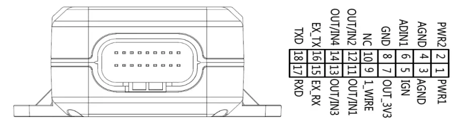
The 18-pin Connector on the GV600WG
Table 5. Description of 18-pin Connections
| Index | Description | Comment |
| 1 | PWR1 | Primary Power 8-32V |
| 2 | PWR2 | Secondary Power 8-32V |
| 3 | AGND | Primary Analogue Ground |
| 4 | AGND | Secondary Analogue Ground |
| 5 | IGN | Ignition Detection Input, Positive Trigger |
| 6 | ADIN1 | Analogue Input 0-32V |
| 7 | OUT_3V3 | External Accessory Power 400mA Max |
| 8 | GND | External Accessory Ground |
| 9 | 1_WIRE | Temperature Sensor Input |
| 10 | NC | NC |
| 11 | OUT/IN1 | Negative trigger input1 for normal use or Open drain output1 150mA max drive current |
| 12 | OUT/IN2 | Negative trigger input2 for normal use or Open drain output2 150mA max drive current |
| 13 | OUT/IN3 | Negative trigger input3 for normal use or Open drain output3 150mA max drive current |
| 14 | OUT/IN4 | Negative trigger input4 for normal use or Open drain output4 150mA max drive current |
| 15 | EX_RX | RS232 RX |
| 16 | EX_TX | RS232 TX |
| 17 | RXD | UART RXD TTL |
| 18 | TXD | UART TXD TTL |
GV600WG Standard Cable Color
GV600WG Standard Cable Color Definition
Definition | Color | Pin No. | Connector | Pin No. | Color | Definition |
PWR1 | Red | 1 | 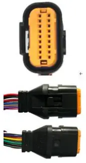
| 2 | Red/Green | RWR2 |
| AGNG | Black | 3 | 4 | Black | AGNG | |
IGN | White | 5 | 6 | Green | ADIN1 | |
| OUT-3V3 | Red/White | 7 | 8 | Black/White | GND | |
1-WIRE | Gray | 9 | 10 | NC | NC | |
| OUT/IN1 | Blue | 11 | 12 | Yellow | OUT/IN2 | |
OUT/IN3 | Brown | 13 | 14 | Orange | OUT/IN4 | |
| EX_RX | Purple | 15 | 16 | Purple/White | EX_TX | |
RXD | Pink | 17 | 18 | White/Black | TXD |
Note:
The main color of the dual color cable is the first color, for example, Black/White means black is the main color, and white is the secondary color.
Getting Started
Open and Close the Case
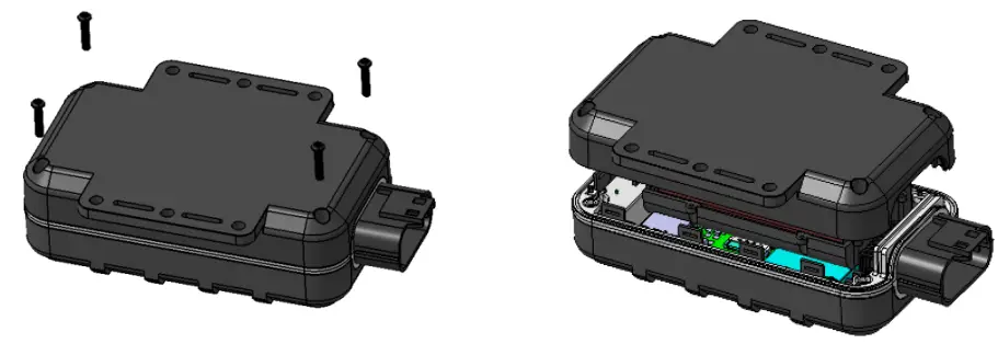
- To open: Use a cross screwdriver to loosen the four screws and then lift the top case gently.
- To close: Align the top case with the bottom case and then tighten the four screws.
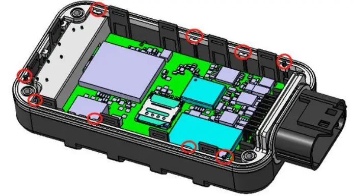
Note:
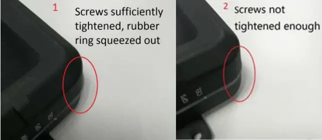
Pay attention to the following details to close the case. Otherwise, the waterproof capability of the device may be deteriorated.
- The positioning poles (total 11) on the top cover must be inserted into the holes of the rubber ring as shown below.

- Tighten the screws sufficiently until the rubber ring is squeezed out as shown in the following figure 1.

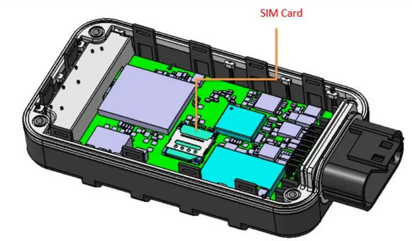
Install a SIM Card
Open the case and ensure the unit is powered off (unplug the 18-pin cable and switch the internal battery to the OFF position). Insert the SIM card into the holder. Take care to align the cut mark and ensure the SIM card is pushed into the SIM holder completely. Close the case.
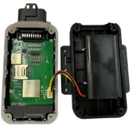
Install the Internal Backup Battery and Close the Case
GV600WG has an internal backup Li-ion battery (5200mAH).
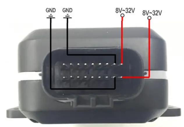
Power Supply Connection
PWR (pin 1 or pin 2)/GND (pin 3 or pin 4) are the power input pins. The input voltage range is from 8V to 32V. The device is designed to be installed in vehicles that operate on 12V or 24V systems without the need of external transformers.
Ignition Detection
Table 7. Electrical Characteristics of Ignition Detection
| Logical Status | Electrical Characteristics |
| Active | 5V to 32V |
| Inactive | 0V to 3V or open loop |
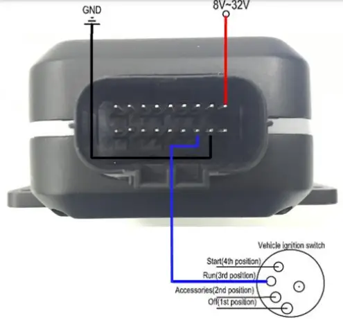
IGN (pin 5) is used for ignition detection. It is recommended to connect this pin to the “RUN” position of the vehicle ignition switch as shown above.
An alternative to connect to the ignition switch is to find a non-permanent power source that is only available when the vehicle is running, for example, the power source for the FM radio.
IGN signal can be configured to transmit information to the backend server when ignition is on and enter the power saving mode when ignition is off.
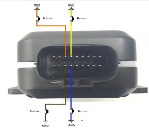
Digital Inputs
There are four general purpose digital inputs on GV600. They all are negative triggers.
Table 8. Electrical Characteristics of the Digital Inputs
| Logical Status | Electrical Characteristics |
| Active | 0V to 0.8V |
| Inactive | Open loop |
The following picture shows the recommended connection of a digital input.
Analogue Inputs
There is one analogue input on GV600WG, and the analogue input voltage range is from 0 to 32V. The following picture shows the recommended connection.
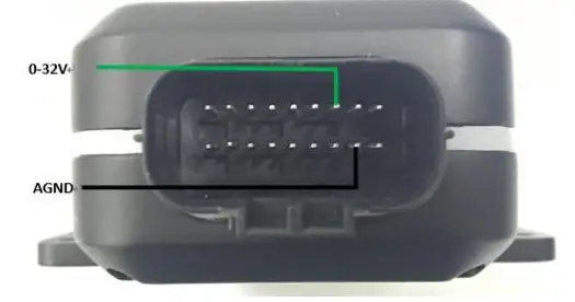
Note:
Pin 6 is a multifunction pin: it can be configured as an analogue input.
Digital Outputs
There are four digital outputs on GV600WG. All are of open drain type and the maximum drain current is 150 mA. Each output has a built-in over current PTC resettable fuse.
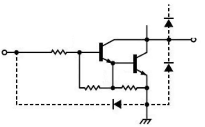
Table 9. Electrical Characteristics of Digital Outputs
| Logical Status | Electrical Characteristics |
| Enable | <1.5V @150 mA |
| Disable | Open drain |
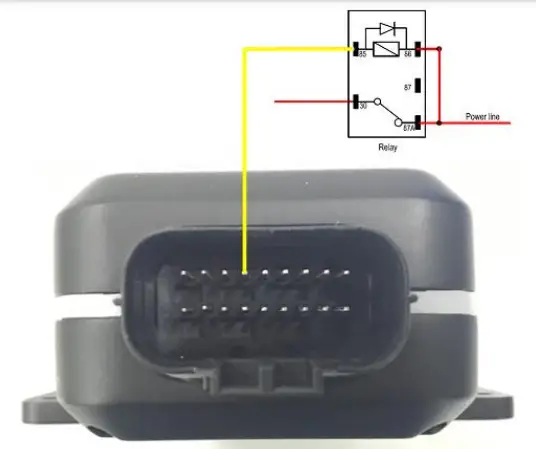 Typical Connection with a Relay
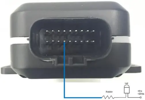 Typical Connection with a LED
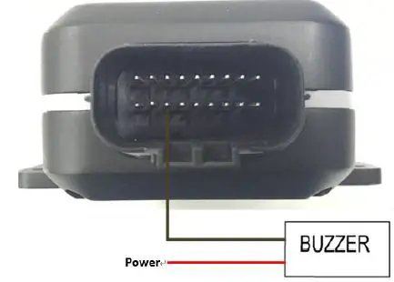 Typical Connection with a Buzzer
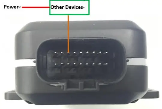 Typical Connection with Other Devices
Note:
Pay attention to the polarity of the relay if it is pre-installed with an internal flyback diode during connection. Install an additional diode externally if there is no pre-installed internal diode. A common diode such as a 1N4004 one will work in most circumstances.
Device Status and LED
Table 10. Definition of Device Status and LED
| LED | Device Status | LED Status |
| CELL (Note 1) | Device is searching CELL network. | Fast flashing (Note 3) |
| Device has registered to CELL network. | Slow flashing (Note 4) | |
| Device goes into sleep mode. | OFF | |
| SIM card needs pin code to unlock. | ON | |
| GPS (Note 2) | GPS chip is powered off. | OFF |
| GPS sends no data or data format error occurs. | Slow flashing | |
| GPS chip is searching GPS info. | Fast flashing | |
| GPS chip has gotten GPS info. | ON | |
| PWR (Note 2) | No external power and internal battery voltage is lower than 3.46V. | OFF |
| No external power and internal battery voltage is below 3.6V. | Slow flashing | |
| External power in and internal battery is charging. | Fast flashing | |
| External power in and internal battery is fully charged. | ON |
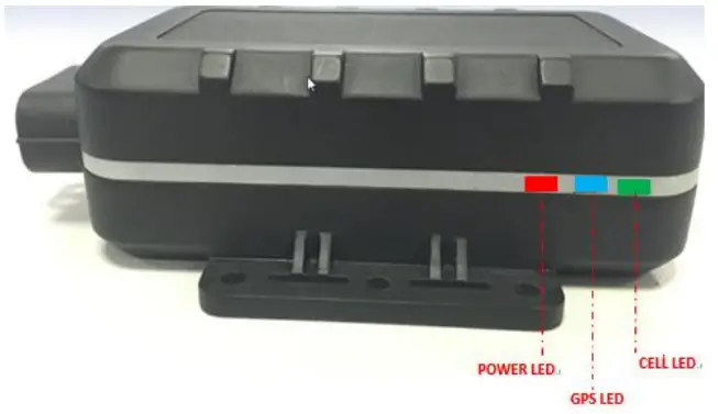 GV600WG LEDs on the Case
Note:
- LED cannot be configured.
- Fast flashing: about 100ms ON/200ms OFF
- Slow flashing: about 200ms ON/1000ms OFF
Temperature Sensor Interface
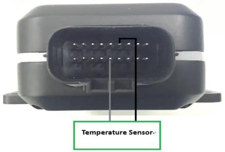 Typical Connection with a Temperature Sensor
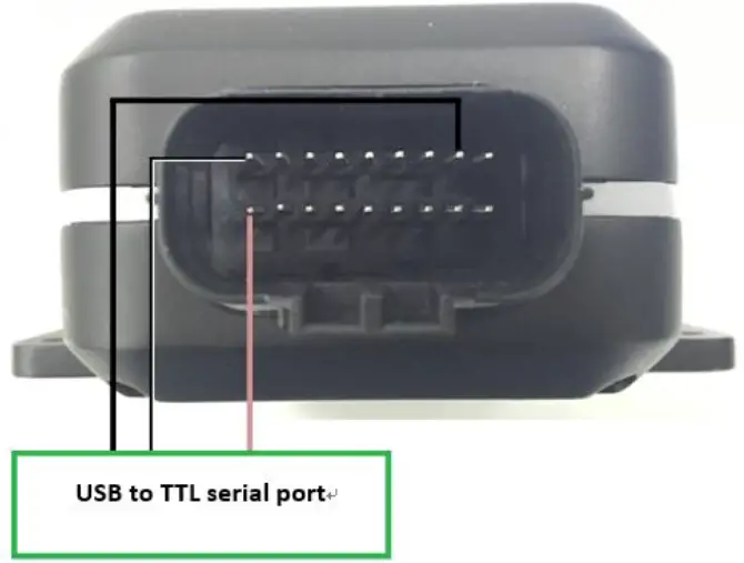 Typical Connection with USB to TTL Serial Port
Supported Peripheral List
| Name | Description |
| Temperature Sensor | 1-Wire temperature sensor DS18B20 |
| Fuel level Sensor | Digital RS232 (DUT-E COM Protocol) Ultrasonic fuel level sensor UFS300 |
| Bluetooth Sensor | BLE 4.2 protocol supported |
| iButton | Supported (should be used with iButton reader) |
CE Declaration
Hereby, Queclink Wireless Solutions Co., Ltd. declares that the radio equipment type GPS tracker is in compliance with Directive 2014/53/EU.
The full text of the EU declaration of conformity is available at the following internet address: http://www.queclink.com/
FCC Statement:
This device complies with part 15 of the FCC rules. Operation is subject to the following two conditions:
- This device may not cause harmful interference, and
- This device must accept any interference received, including interference that may cause undesired operation.
This Class B digital apparatus complies with Canadian ICES-003.
NOTE: The manufacturer is not responsible for any radio or TV interference caused by unauthorized modifications to this equipment. Such modifications could void the user’s authority to operate the equipment.
NOTE: This equipment has been tested and found to comply with the limits for a Class B digital device, pursuant to part 15 of the FCC Rules. These limits are designed to provide reasonable protection against harmful interference in a residential installation. This equipment generates uses and can radiate radio frequency energy and, if not installed and used in accordance with the instructions, may cause harmful interference to radio communications. However, there is no guarantee that interference will not occur in a particular installation. If this equipment does cause harmful interference to radio or television reception, which can be determined by turning the equipment off and on, the user is encouraged to try to correct the interference by one or more of the following measures:
- Reorient or relocate the receiving antenna.
- Increase the separation between the equipment and receiver.
- Connect the equipment into an outlet on a circuit different from that to which the receiver is connected.
- Consult the dealer or an experienced radio/TV technician for help
- This device and its antenna(s) must not be co-located or operating in conjunction with any other antenna or transmitter.
RF Exposure Information:
This equipment complies with FCC exposure limits set forth for an uncontrolled environment. This equipment should be installed and operated with minimum distance of 20 cm between the radiator and your body. This transmitter must not be co-located or operating in conjunction with any other antenna or transmitter.


