TRITON Neo Eight Rectangular Sliding Door Shower Installation Guide
SAFETY
- Handle glass with great care. Although the glass is very tough, sharp impacts can damage both the glass and metal frame.
- Make sure there are no hidden pipes or cables hidden in the wall where you intend to drill.
- Wear safety goggles, shoes and appropriate clothing.
BEFORE INSTALLATION
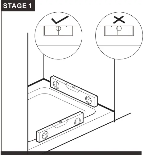
- Check that the shower tray is level in all directions. The enclosure will not sit correctly on an uneven surface. If uneven, the wall channels may not fit and the doors may not shut correctly.
- The enclosure should be fitted on tiled walls which are sealed with waterproof grout.
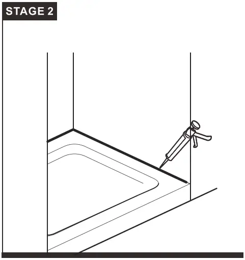
- There must be a good silicone seal between the rim of the shower tray and the wall.
- The shower tray and the enclosure must match in size. Attempting to fit the incorrect size of enclosure to the shower tray will result in water leaks.
- Always check very carefully that components are vertical.
- To avoid damage, use the opened out packaging to build the enclosure on.
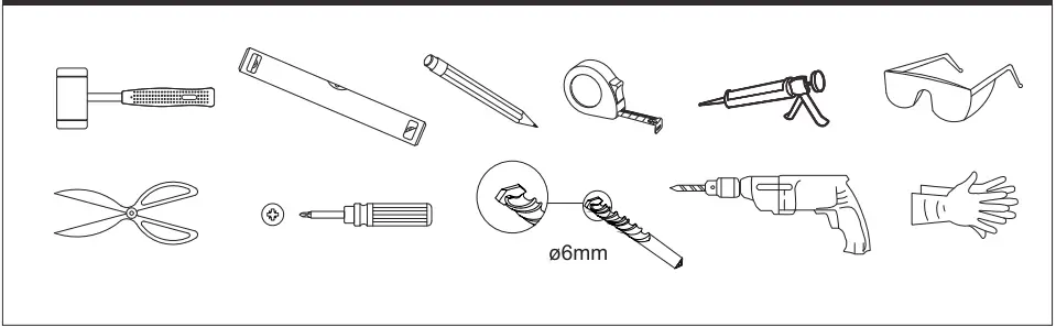
Equipment needed: Drill. 6.0mm Masonry Bit. Crosshead PH2 Screwdriver . Spirit Level. Pencil. Tape Measure. Silicone Sealant.
Note: The screws and wall plugs supplied are for masonry walls. For lightweight walls i.e. stud partition, plasterboard etc, use the correct type of fixings.
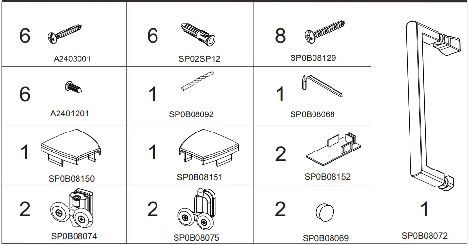
FIXING KIT COMPONENTS
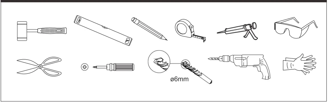
TOOLS REQUIRED
| SLIDER DOOR CODE | DOOR SIZE IN MM | OVERALL ADJUSTMENT IN RECESS mm |
| TN8S10 | 1000 | 930-990 |
| TN8S11 | 1100 | 1030-1090 |
| TN8S12 | 1200 | 1130-1190 |
| TN8S14 | 1400 | 1330-1390 |
Installation instruction
Loosen fixed glass panel clip. Do not remove the screw.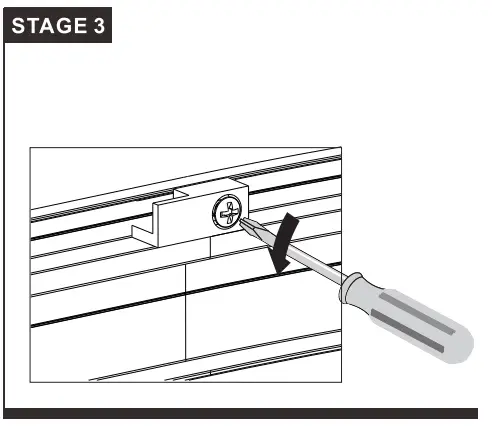
Fix the two fixed panels and upright profiles to the top bottom rail,using SP0B08129 screw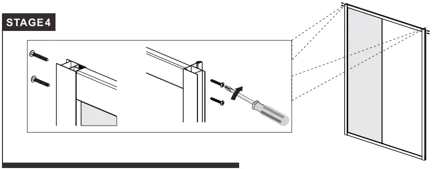
Put a dab of silicone in the corner between glass panel and fixed clip to the bottom when sliding the clip under the glass and back into position.Ensure bottom seal is present on glass,remove small corner protector/seal if present.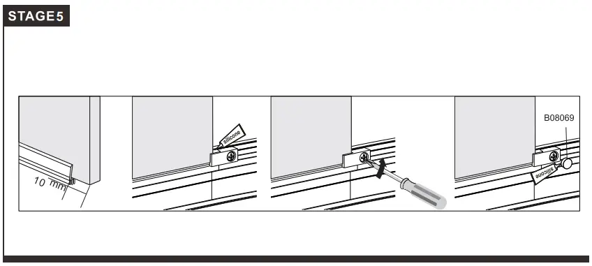
Fitting the wall profile
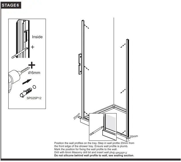
Fit both wall profile onto the frame, then lift the frame onto the tray, keep side of profile with fixing holes to the inside, fix both profiles with 30mm screws A2403001.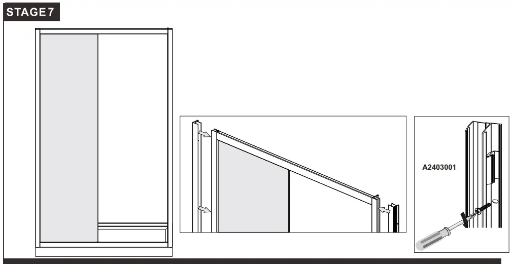
Install Moving Panel
Fit the rollers,to the moving panel.
Note:ensure OUTSIDE label is facing the outside.Spring loaded roller are to be located at the bottom Hang the doors onto the top track, and push the spring loaded button on the bottom rollers and ease the rollers into the bottom rail.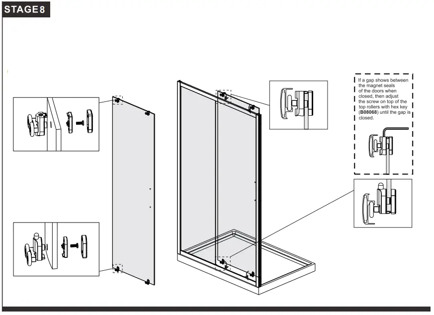
Secure Wall Channel & Upright Profile
Once you have check that the door opens and the closes correctly,fix the door frame to the wall channels.From inside,drill 3 holes through each wall channel/door frame using 3.0mm drill bit.Fix using A2401201.
Important
Please follow the right diagram for drilling, so as not to frill into the glass, frame for the screw to fix both profiles.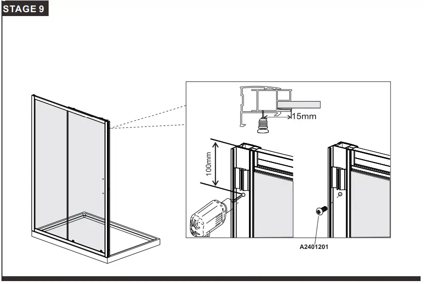
Push the upright seals SP0B08117 onto the fixed panels,and the upright seals SP0B08080 onto the moving panel.(As shown diagram below).Attach cover strip SP0B08138 to the wall profile.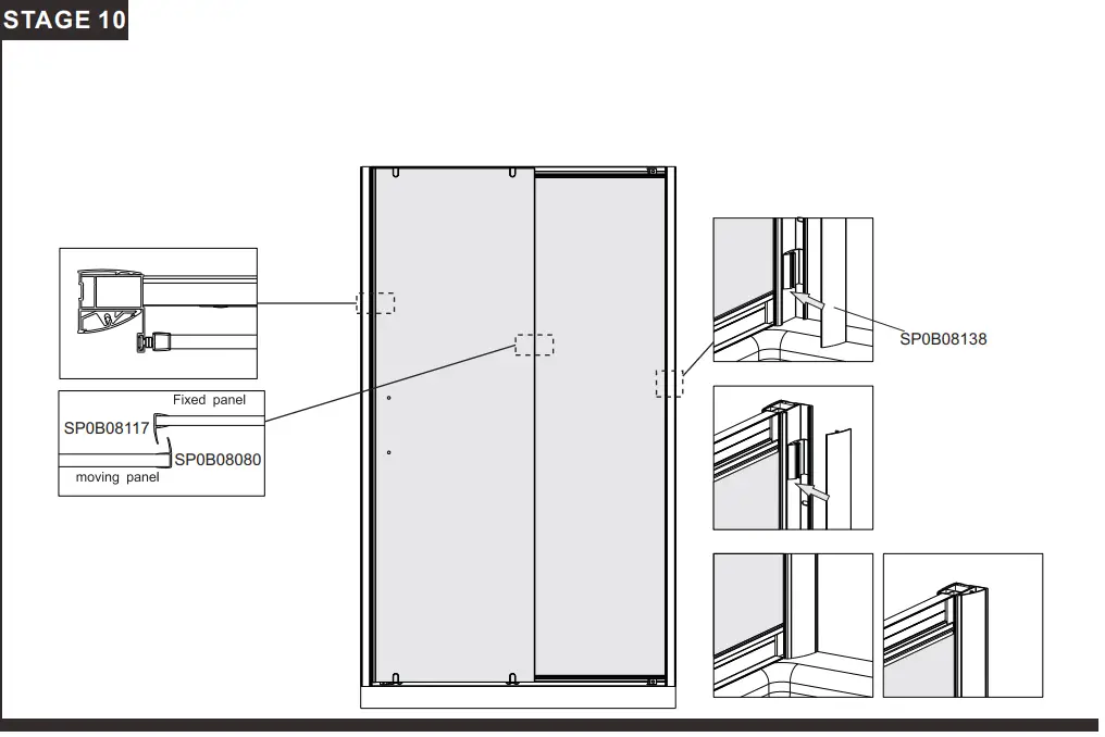
Use a quality silicone sealant to seal the finished door. Seal joints between the upright profiles and the bottom rail.
Sealing Inside Seal top to bottom on the INSIDE between the wall profile and the wall.
Note: Do not apply sealant on inside of tray.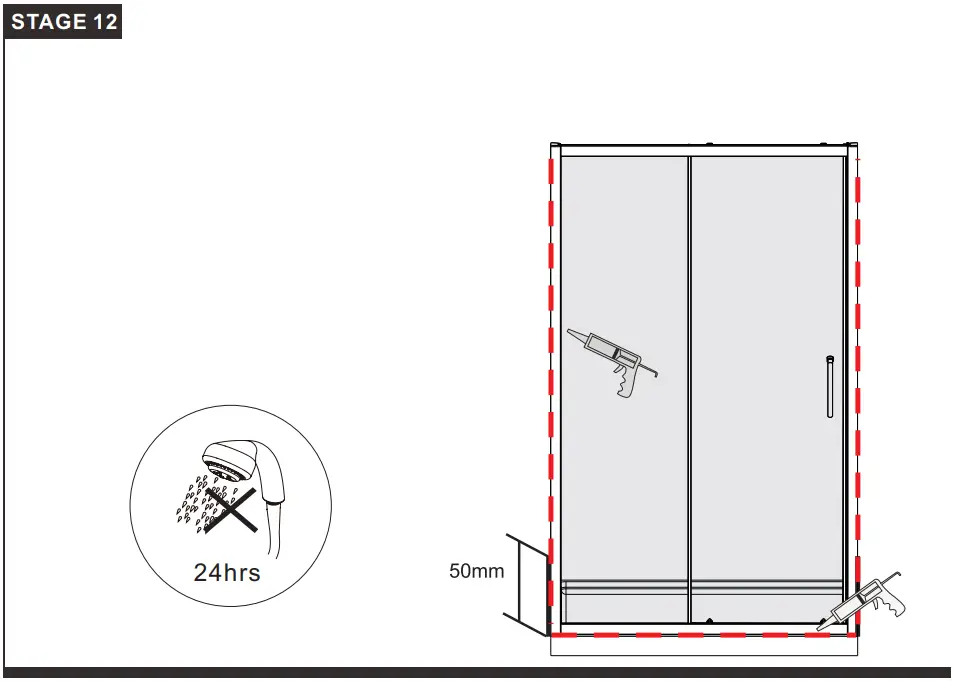
Sealing Outside
Seal only along bottom rail on the OUTSIDE between profile and the the tray and approx 50mm up between the
wall profile and the wall.
Seal also where wall profile and frame profile overlap 50mm up.
Seal also the joints between the bottom profile and the upright profiles.
Parts List
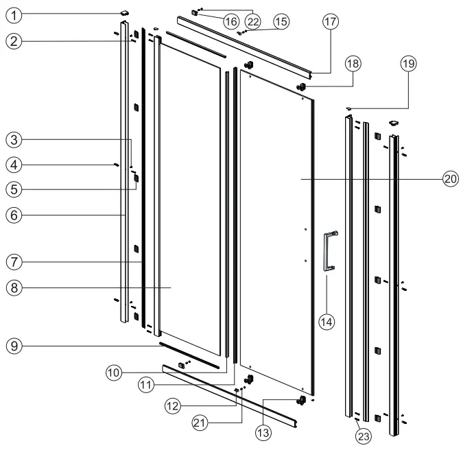
| Item No. | Part List Description | Part Code | Sliding Door Size Variations | |||
| 1000 | 1100 | 1200 | 1400 | |||
| 1 | Cover cap for wall profile L/R | SP0B08150/ SP0B08151 | 2 | 2 | 2 | 2 |
| 2 | Screw ST4X30 | A2403001 | 6 | 6 | 6 | 6 |
| 3 | Flat head screw ST4X12 | A2401201 | 6 | 6 | 6 | 6 |
| 4 | Wall plug | SP02SP12 | 6 | 6 | 6 | 6 |
| 5 | Cover strip clip | SP0B08147 | 10 | 10 | 10 | 10 |
| 6 | Wall profile | SP0B08135 | 2 | 2 | 2 | 2 |
| 7 | Cover Strip | SP0B08138 | 2 | 2 | 2 | 2 |
| 8 | Fixed panel -various sizes | N/A | 1 | 1 | 1 | 1 |
| 9 | 8mm Fixed bottom seal 30mm | SP0B08146 | 2 | 2 | 2 | 2 |
| 10 | Upright water seal for fixed panel | SP0B08117 | 1 | 1 | 1 | 1 |
| 11 | Upright water seal for moving panel | SP0B08080 | 1 | 1 | 1 | 1 |
| 12 | Glass clip (L/R) | SP0B08120/ SP0B08121 | 2 | 2 | 2 | 2 |
| 13 | Bottom roller | SP0B08075 | 2 | 2 | 2 | 2 |
| 14 | Handle | SP0B08072 | 1 | 1 | 1 | 1 |
| 15 | Glass clip cover cap | SP0B08069 | 2 | 2 | 2 | 2 |
| 16 | Roller stop (L/R) | SP0B08065L/ SP0B08065R | 2 | 2 | 2 | 2 |
| 17 | Top & bottom rail 1000mm | SP0B08139/ SP0B08140 | 1 | |||
| 17 | Top & bottom rail 1100mm | SP0B08166/ SP0B08167 | 1 | |||
| 17 | Top & bottom rail 1200mm | SP0B08141/ SP0B08142 | 1 | |||
| 17 | Top & bottom rail 1400mm | SP0B08143/ SP0B08144 | 1 | |||
| 18 | Top Roller | SP0B08074 | 2 | 2 | 2 | 2 |
| 19 | Cover cap upright profile | SP0B08152 | 2 | 2 | 2 | 2 |
| 20 | Movingpanel- various sizes | N/A | 1 | 1 | 1 | 1 |
| 21 | Glass clip screw ST4X10 | SP0B08089 | 2 | 2 | 2 | 2 |
| 22 | Roller stop screw ST4X10 | SP0B08089 | 2 | 2 | 2 | 2 |
| 23 | Screw ST4X40 | SP0B08129 | 8 | 8 | 8 | 8 |
SIDE PANEL INSTALLATION GUIDE
Please read these instructions carefully and keep for future reference. Incorrect fitting will invalidate the guarantee.
Note: Instructions show fittingof a side panel with a sliding door as an example only.This side panel can be fitted with any Series door.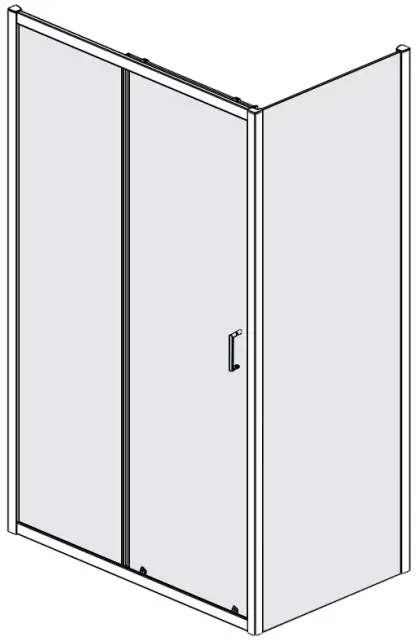
SAFETY
- Handle glass with great care. Although the glass is very tough, sharp impacts can damage both the glass and metal frame.
- Make sure there are no hidden pipes or cables hidden in the wall where you intend to drill.
- Wear safety goggles, shoes and appropriate clothing.
BEFORE INSTALLATION
- Check that the shower tray is level in all directions. The enclosure will not sit correctly on an uneven surface. If uneven, the wall channels may not fit and the doors may not shut correctly.
- The enclosure should be fitted on tiled walls which are sealed with waterproof grout.
- There must be a good silicone seal between the rim of the shower tray and the wall.
- The shower tray and the enclosure must match in size. Attempting to fit the incorrect size of enclosure to the shower tray will result in water leaks.
- Always check very carefully that components are vertical.
- To avoid damage, use the opened out packaging to build the enclosure on.
Equipment needed:
Drill. 6.0mm Masonry Bit. Crosshead PH2 Screwdriver . Spirit Level. Pencil. Tape Measure. Silicone Sealant. Note: The screws and wall plugs supplied are for masonry walls. For lightweight walls i.e. stud partition, plasterboard etc, use the correct type of fixings.
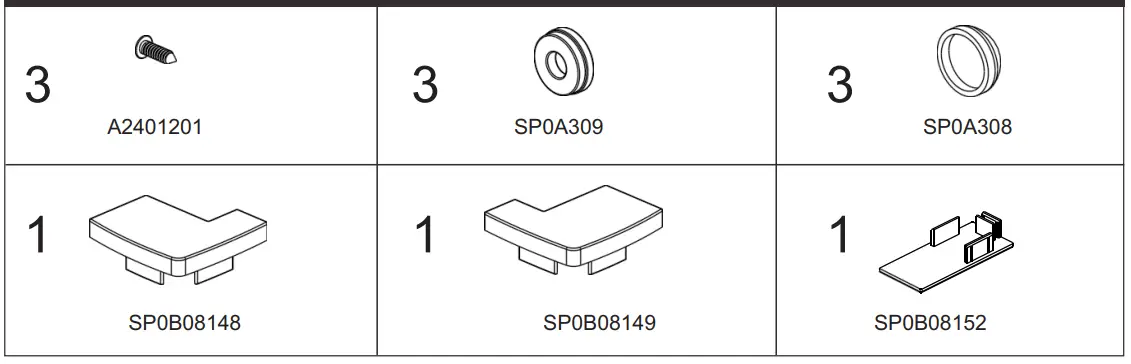
Fixing kit Components
Tools Required
| SIDE PANEL CODE | PANEL SIZE IN MM | OVERALL ADJUSTMENT IN MM |
| TN8SP76 | 760 | 720 -750 |
| TN8SP80 | 800 | 760 -790 |
| TN8SP90 | 900 | 860 -890 |
Step wall profile in 20mm from edge of tray and plumb. Make sure fixing holes are to the inside.
Mark wall through slots in profile.
Note: For installation of the pivot door, bifold door or sliding door, please see the door instruction manual.
If fitting with a sliding door it is recommended to have the moving panel closing against the side panel. (See Stage 4).
Drill holes using 6mm bit and insert wall plugs.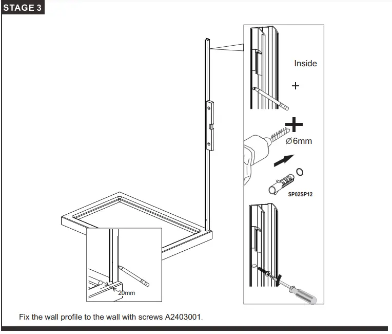
Insert the side panel into the wall profile and also into the frame of the slidin.g door.
Adjust so it is positioned correctly on the tray.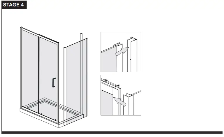
Drill 3 equally spaced holes with 3mm drill bit through the upright profile,corner profile.
Fix the frame with screw clip ,screws and screw cap.
Then fix the upright profile cover and corner profile cover.
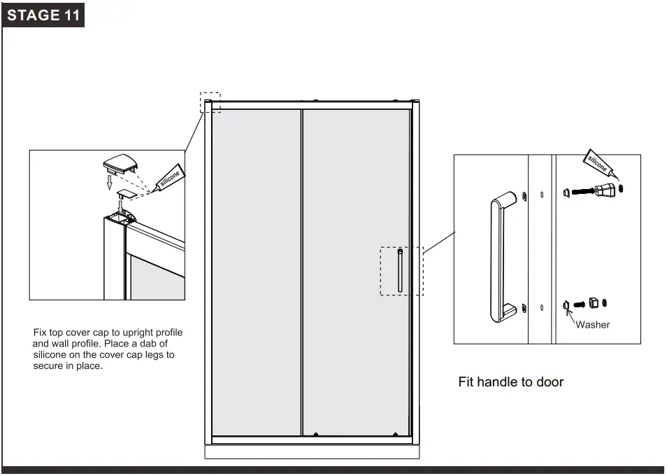
Place a dab of silicone on the cover cap legs to secure in place.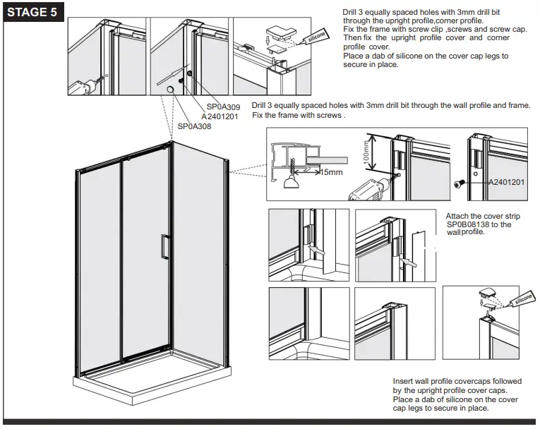
Insert wall profile cover caps followed by the upright profile cover caps. Place a dab of silicone on the cover cap legs to secure in place.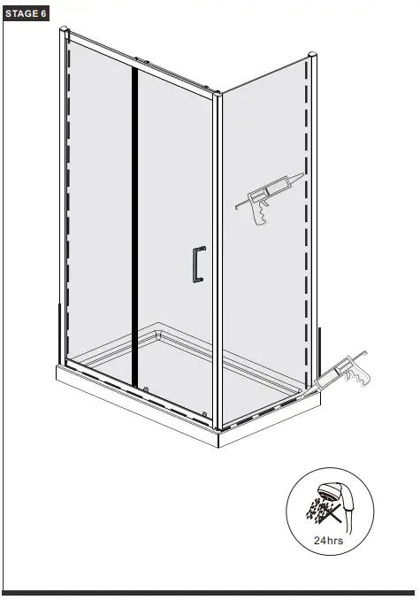
Use a quality silicone sealant to seal the finished door. Sealing Inside
Seal top to bottom on the INSIDE between the w. all profile and the wall.
Note: Do not apply sealant on inside of tray.
Sealing Outside
Seal only along bottom rail on the OUTSIDE between profile and the tray and approx 50mm up between the wall profile and the wall.
Seal also where bottom profile and frame profile overlap 50mm up.
Parts List
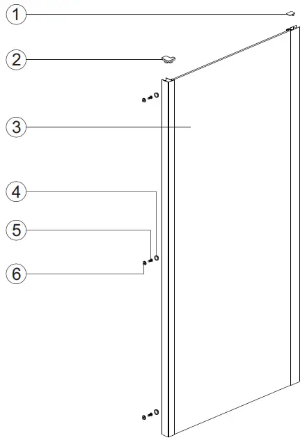
| Item No. | Part List Description | Part Code | Side Panel Size Variations | ||
| 760 | 800 | 900 | |||
| 1 | Cover cap for upright profile | SP0B08152 | 1 | 1 | 1 |
| 2 | Corner post profile cover L/R | SP0B08148 / SP0B08149 | 1 | 1 | 1 |
| 3 | Fixed panel – various size | N/A | 1 | 1 | 1 |
| 4 | Screw cap | SP0A308 | 3 | 3 | 3 |
| 5 | Corner profile screw ST4x12 | A2401201 | 3 | 3 | 3 |
| 6 | Screw clip | SP0A309 | 3 | 3 | 3 |


