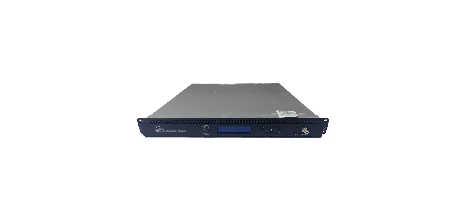
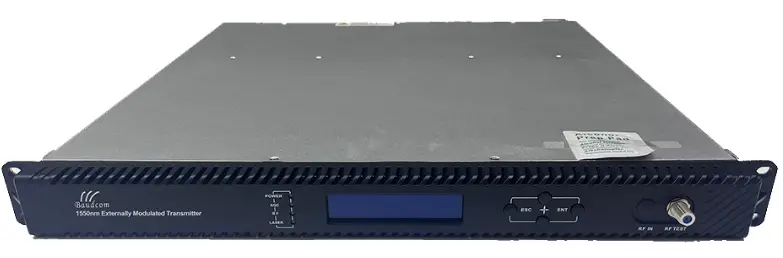
Baudcom BD-5800H 1550nm External Modulated Optical Transmitter

Overview
About This Manual
This instruction manual is a complete guide to install and operate the (1RU) 1550nm external modulated optical transmitter. Please read the entire manual before beginning installation. This manual applies to the external modulated optical transmitter.
- Chapter 1 gives general information about the 1550nm external modulated optical transmitter.
- Chapter 2 describes the complete technical specifications of the equipment.
- Chapter 3 describes the front/rear panel interfaces and menu system.
- Chapter 4 tells you how to install the external modulated optical transmitter.
- Chapter 5 tells you the communication setting of the equipment.
- Chapter 6 describes maintenance and what to do in the event of problems.
Product Description
This optical transmitter is a 1550nm DFB laser external modulated transmitter. It is specially developed for the CATV signal that satisfies HFC network, and the long-distance transmission of cable phone and cable data.
Working principle
It has 7 function modules: RF control, DFB laser, optical modulator, SBS control, CSO control, communication/display control and power supply.
Automatic gain control circuit (AGC) or manual gain control circuit (MGC) amplifies the RF signal. AGC or MGC control makes the optical modulator maintain a suitable input level. Use the detected RF root-meansquare(RMS)-total power to calculate the optical modulation index(OMI). In general we recommend using the AGC function, and special users can use the MGC function to adjust the CNR/CSO/CTB performance indexes. The core of the transmitter is the optical modulator. The 1550nm signal input the optical modulator, make the laser intensity changed follow the external RF signal voltage, and then generate the AM optical signal. Stimulated Brillouin Scattering (SBS) occurs, when the optical input power is greater than a certain threshold value. SBS generate the lower frequency backscattered light which will attenuate the transmission light and return to the laser while destroying its performance. Causing optical power fluctuation, generates large noise, and seriously deteriorates the system carrier to noise ratio (CNR). To improve the SBS threshold, this optical transmitter adopts SBS control technology which is independent researched and developed by ourselves. The threshold value can be set up to 19dBm.
The optical modulator has a two-way optical signal output. Parts of that signal are routed to an InGaAs photodiode. This detection of the optical signal has two functions:
- Detect whether the laser is normal working. Once the output optical power is 2dB lower than standard power, alarm will be set off.
- Detect CSO distortion to optimize the bias point of the optical modulator. For working normal the detector circuit needs at least two carrier signal inputs with an interval of 24MHz. There is a CSO initialization program in the boot process. If the CSO install failed, the RF indicator will flash red, see details in 6.2 Troubleshooting.
Block Diagram 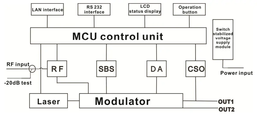
Product Applications
- High-performance long-distance transmission
- High-power distribution network
- Redundancy loop architecture
- FTTx network
- RFOG application
- DWDM network
Technique Parameters
Optical Parameters
| Item | Unit | Value |
| Optical Wavelength | nm | 1545~1560 (or specified by the user) |
| Side-mode Suppression ratio | dB | >30 |
| Relative Intensity Noise | dB/Hz | <-160 |
| Wavelength Adjustment Range | GHz | +/-50GHz |
| Optical Power | dBm | 2*5, 2*7, 2*8, 2*9, 2*10 |
| SBS Threshold Value | dBm | +13~+19 (Continuously adjustable) |
| Laser Linewidth | MHz | 0.3 |
Model Test Indicators
| Test Model | C42 | D59 | D84 | D84 |
| Channel Plan | CENELEC42 | PAL D59 | PAL D84 | PAL D |
| Channel Number TV/FM/QAM64 | 42/0/0 | 59/0/0 | 84/0/0 | 30/0/48 |
| Bandwidth Noise | 5 | 5 | 5 | 5 |
| CNR Tx/Rx | 55.5 | 54.0 | 52.5 | 54.5 |
| CNR Link 1 | 55.0 | 53.5 | 52.0 | 54.0 |
| CNR Link 2 | 53.0 | 52.5 | 50.5 | 52.5 |
| CNR Link 3 | 50.5 | 50.5 | 49.0 | 51.0 |
| CSO Tx/Rx and Link 1 | 64 | 65 | 65 | 70 |
| CSO Link 2 | 63 | 65 | 65 | 70 |
| CSO Link 3 | 62 | 64 | 63 | 65 |
| CTB | 65 | 65 | 65 | 68 |
Test Condition
| First stage EDFA | First paragraph fiber length | Second stage EDFA | Second paragraph fiber length | RX | SBS (dBm) | |
| Tx/Rx | No | No | No | no | 0dBm | 13.5 |
| Link 1 | No | 35km | no | no | 0dBm | 13.5 |
| Link 2 | 16dBm | 65km | no | no | 0dBm | 16 |
| Link 3 | 13dBm | 50km | 13dBm | 50km | 0dBm | 13.5 |
Rx with 8 pA/ÖHz input noise current density; EDFA with 5dB noise figure; RF input level at 80 dBμV / TV channel;
Technical Data Sheet
| Item | Unit | Technical Parameters |
| RF range | MHz | 47~1003 |
| RF flatness | dB | +/-0.75 |
| RF return loss | dB | >16 |
| RF input impedance | Ω | 75 |
| RF input connector type | F type | |
| Rated input level | dBµV | 80 |
| Input level range | dBµV | 78~96 (AGC mode, modulating signal) |
| AGC control range | dB | +3~-3 |
| MGC adjustable range | dB | 0~15 |
| Optical connector | SC/APC, FC/APC | |
| Operating temperature | °C | -5~45 |
| Storage temperature | °C | -30~+70 |
| Power Source Specification | V | 90~265VAC |
| 36~72VDC | ||
| Consumption | W | ≤60 |
| Dimension | mm | 483(L) × 455(W) × 44(H) |
| Total Weight | kg | 5.5 |
Front Panel
| 1 | Power indicator | 2 | AGC indicator | 3 | RF modulation degree indicator |
| 4 | Laser indicator | 5 | LCD | 6 | ESC key |
| 7 | UP key | 8 | DOWN key | 9 | Enter key |
| 10 | RF input port (or on the rear panel, optional) | 11 | -20dB RF input test port |
Indicator Description
| Power indicator | One power supply | LED yellow |
| Two power supplies | LED green | |
| AGC indicator | AGC mode | LED green |
| MGC mode | LED off | |
| RF modulation degree indicator | Normal | LED green |
| Abnormal | LED flash red | |
|
Laser indicator | Bias current, cooling current and output power are all normal | LED green |
| At least one of bias current, cooling current and output power is abnormal | LED flash red |
Rear Panel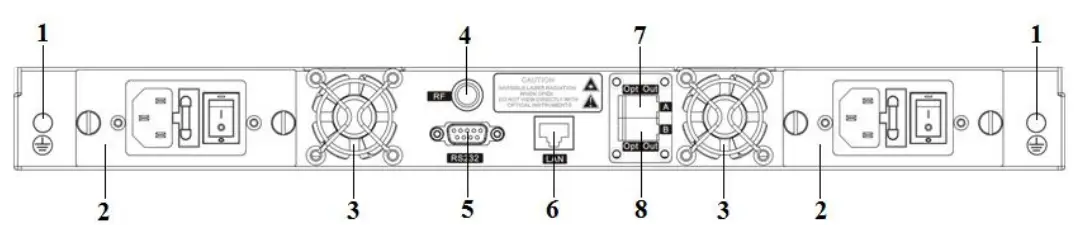
| 1 | Ground stud | 2 | Power module | 3 | Fan |
| 4 | RF input port (or on the front panel, optional) | 5 | RS232 interface | 6 | LAN interface |
| 7 | Optical output interface A (or on the front panel, optional) | 8 | Optical output interface B (or on the front panel, optional) |
Power Module
220V Power Module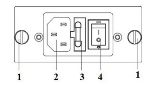
| 1 | Mounting screws | 2 | 220V power outlet | 3 | Fuse |
| 4 | Power switch |
48V Power Module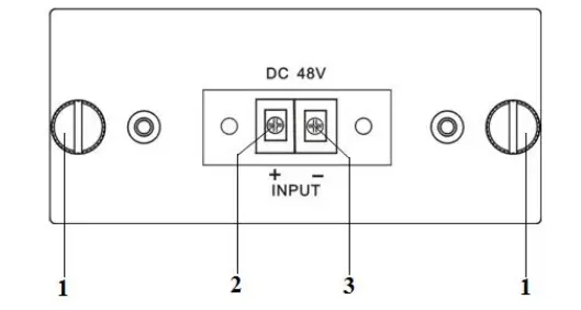
| 1 | Mounting screws | 2 | + Positive terminal block | 3 | – Negative terminal block |
Main Menu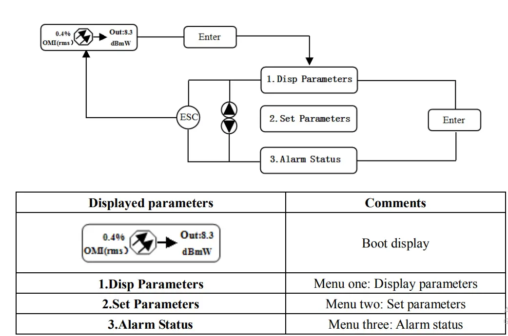
Display Menu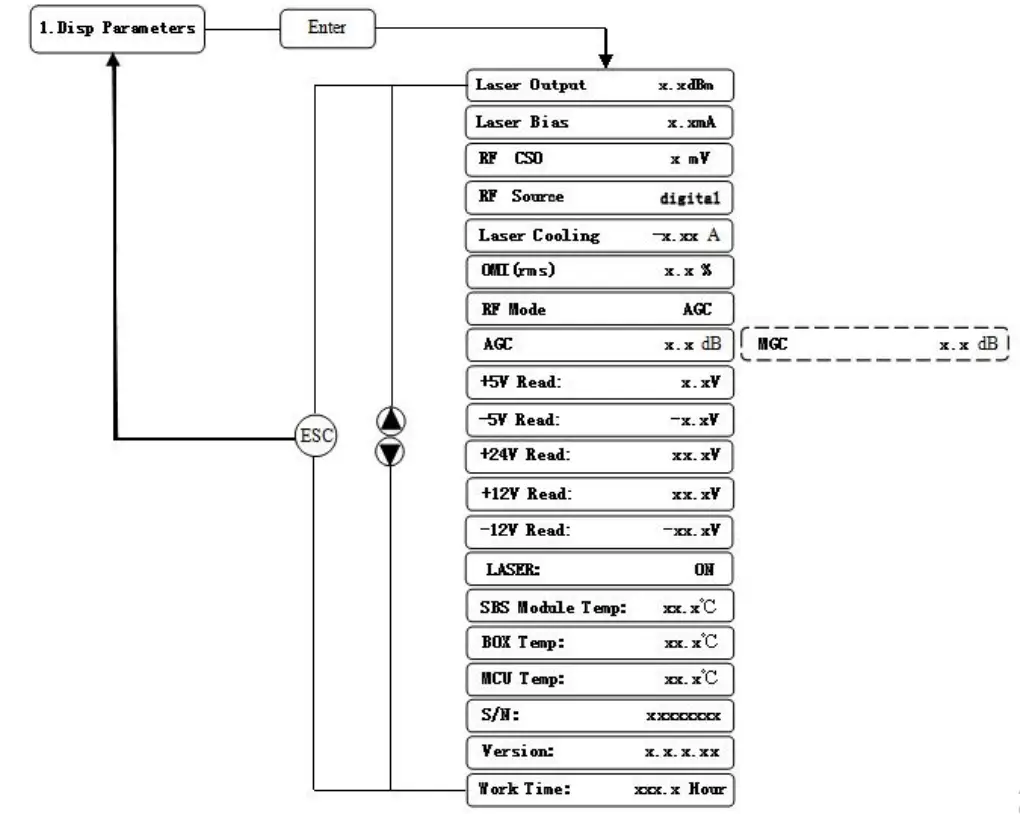
| Displayed parameters | Comments | Displayed parameters | Comments |
| Laser Output | Output optical power | +24V Read: | +24V monitor voltage |
| Laser Bias | Laser current | +12V Read: | +12V monitor voltage |
| RF CSO | CSO monitor voltage | -12V Read: | -12V monitor voltage |
| RF Source | The current RF signal source | LASER: | Laser status |
| Laser Cooling | Cooling current | SBS Module Temp: | SBS module temperature |
| OMI(rms) | Total modulation degree | BOX Temp: | Overall temperature |
| RF Mode | RF control mode | MCU Temp: | MCU temperature |
| AGC | Adjusted value with AGC mode | S/N: | Serial number |
| MGC | Adjusted value with MGC mode | Version: | Version number |
| +5V Read: | +5V monitor voltage | Work Time: | Work time |
| -5V Read: | -5V monitor voltage |
Set Menu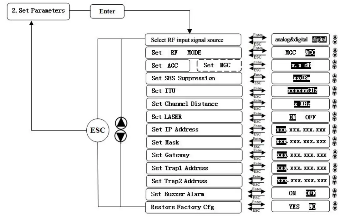
| Displayed parameters | Comments | Remarks | |
| Select RF input signal source | Select RF input signal | Analong&digital full analog signal or analog and digital mixed signal Digital full digital signal | |
| Set RF MODE | Set RF control mode | MGC and AGC two modes selectable | |
| Set AGC | Set MGC | Set RF adjusted value | Adjustable range 0~15dB with MGC mode Adjustable range -3~+3dB with AGC mode |
| Set SBS Suppression | Set SBS value | Range 13~19dBm, 0.5dB stepping | |
| Set ITU | Set optical wavelength | Range ±50GHz | |
| Set Channel Distance | Set channel distance | 6MHz, 7MHz, 8MHz | |
| Set LASER | Set laser status | ON/OFF | |
| Set IP Address | Set IP address | ||
| Set Mask | Set subnet mask | ||
| Set Gateway | Set gateway | ||
| Set Trap1 Address | Set trap1 address | ||
| Set Trap2 Address | Set trap2 address | ||
| Set Buzzer Alarm | Set buzzer alarm | ON/OFF | |
| Restore Factory Cfg | Restore factory settings | ||
Alarm Menu
| The displayed alarm content | Comment | |
| RF IN Status | HIGH(LOW) | The RF input signal is high (low) |
| Laser Bias | HIGH(LOW) | The laser bias current is high (low) |
| Laser TEC | HIGH | The laser cooling current is high |
| Output Power Status | HIGH(LOW) | The output optical power is high (low) |
| -5V Status | HIGH(LOW) | The -5V voltage is high (low) |
| +5V Status | HIGH(LOW) | The +5V voltage is high (low) |
| +12V Status | HIGH(LOW) | The +12V voltage is high (low) |
| -12V Status | HIGH(LOW) | The -12V voltage is high (low) |
| +24V Status | HIGH(LOW) | The +24V voltage is high (low) |
| Laser | OFF | The laser is off |
| CSO Initialization failed | The CSO initialization is failed | |
| Power invalid | LEFT(RIGHT ) | The left (right) power is invalid |
AGC Mode
This mode is the recommended mode and also the standard operation. The optical transmitter will automatically adjust to the optimal gain while the input level is in the working range (see the technical data sheet). And the specified OMI (rms) modulation index will be automatic gain control.
MGC Mode
Special users, who need to adjust system CNR/CSO/CTB performance indexes to satisfy the specified requirements, can use this mode. The amplification gain attenuation range 0-15dB.
Frequency Adjust ITU in DWDM
To help DWDM applications, it can adjust optical wavelength. The adjustable range is ±100GHz, 50GHz stepping. The button on the front panel or the Ethernet interface will complete the adjustment.λ=c/f, c is the speed of light. It is the constant value. c=299792458m/s, f is the frequency, its unit is Hz; eg frequency 193400GHZ, the corresponding wavelength is 1550.12nm. In the 1545-1560nm band, the frequency distance and the wavelength distance is very similar to linear relationship. 50GHz frequency distance reflects to wavelength is very approximate to 0.4nm width;
SBS Suppression Adjustment
SBS value is very important in 1550nm long-distance transmission system. Stable continuous coherent light source, add +6 dBm optical power in the standard single mode fiber may occur SBS phenomenon. Ultrahigh SBS threshold will reduce CNR and CSO low-frequency indicators.
High SBS threshold will also influence self phase modulation (SPM) and reduce high-frequency CSO indicator.
When meet the conditions, as far as possible to use a low threshold SBS.
Installing the Optical Transmitter
Receiving and Inspecting
As you unpack your unit, inspect the shipping container and equipment for damage. Save the shipping material for future use. If the container or the equipment is damaged, notify both the freight carrier and us.
Precautions
Heed the following precautions when working with the equipment.
Warning
- Read the installation instructions before connecting the system to the power source.
- The plug-socket combination must be accessible at all times, because it serves as the main disconnecting device.
Mounting the Equipment
Mounting the Equipment in the Rack
Mounting the Equipment in the standard 19 inch equipment rack:
- Place the equipment in the rack.
- Use four screws fixed the mounting lug on its front panel to the rack.
- Reliably ground the equipment. The ground terminal is on the rear panel.
- Visually inspect each key (button) on the front panel to ensure that it is not trapped under the edge of its hole. If a key is trapped, tap the key to enable it to move freely.
Connecting the RF Cables
Verify the RF inputa F connector type according to the ordering information, then screw on the matched RF cable.
Connecting the Optical Fiber Cables
It has two output optical connectors.
- Verify the matched its fiber cable connector type according to the ordering information.
- Verify that the fiber cable connector has been cleaned properly. If the fiber cable connector needs to be cleaned, follow the cleaning procedure outlined in “Cleaning Patch Cord or Pigtail Fiber Optical Connectors”.
- Verify that the optical connector has not been exposed to any contamination.
- Note to butt the nick of the connectors and align them accordingly.
Connecting the Ethernet Cable
You can connect it to your TCP/IP network in order to monitor and control the transmitter remotely. After you complete the installation procedures described in this chapter, you can use a network management system (NMS) to monitor and control the equipment. To connect the equipment, you must use a shielded and grounded Category 5 Ethernet cable. To connect the Ethernet cable:
- Connect an Ethernet cable to the transmitter’s RJ-45 Ethernet port and to your TCP/IP network. The Ethernet port is on the built-in transponder of the transmitter.
- Verify that the green Link LED is illuminated, indicating that there is a connection. The Link LED is above the Ethernet port on the rear panel.
Connecting Power
The is available in an AC power model or DC power model. After mounting the equipment in a rack, follow the power connection procedure below for the model that you are installing.
The AC-powered equipment has two optional power supplies 110V and 220V:
110V power supply has two 110 VAC (50/60 Hz) input connector that requires input voltage from 90 to 130 VAC, at 50 to 60 Hz single phase. The AC power plug is located on the rear panel.
220V power supply has two 220 VAC (50/60 Hz) input connector that requires input voltage from 150 to 265 VAC, at 50 to 60 Hz single phase. The AC power plug is located on the rear panel.
The DC-powered equipment has two -48 VDC input connectors that require input voltage from -36 to -72 VDC. The DC input connectors are located on the rear panel. Turn on the power source. It takes about 60 seconds for all systems to operate. When connect one power supply, the power indicator is yellow; when connect two power supplies, the power indicator is green.
Communication Setup
RS232 Communication Interface Description
Adopt DB9 standard connector, the pin definitions as follow: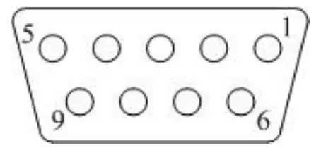
- No Connect
- TX
- RX
- No Connect
- GND
- No Connect
- No Connect
- No Connect
- No Connect
The serial communication uses the standard NRZ form, 1 starts bit, 8 data bits, 1 stop bit and the baud rate is 38400.
Set up the Hyper Terminal
If you have not setup the Hyper Terminal in your Windows system, follow the steps: Click “start menu program accessorycommunicationHyper Terminal”: This results in the following screen: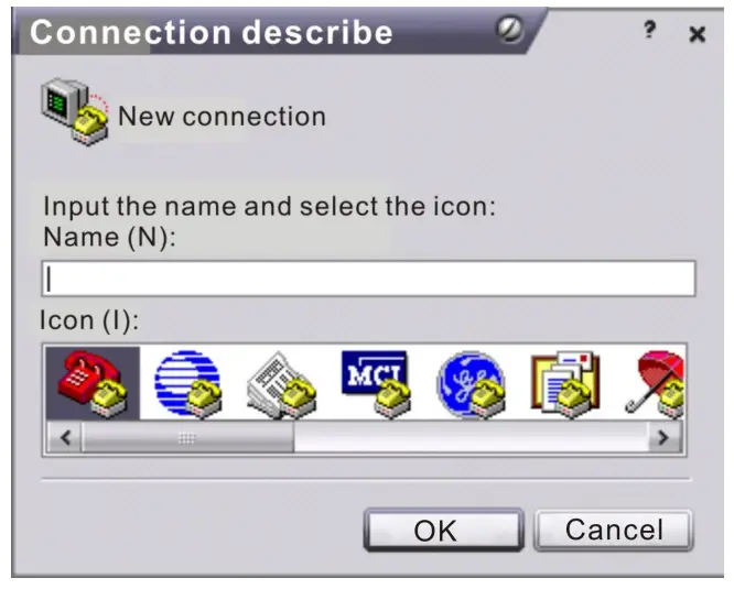
Then you input your connection name, such as “SNMP38400”,and choose the serial port to connect with your equipment. As follows: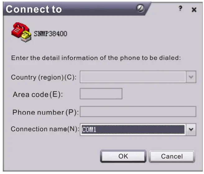
Press the “OK” button shows the configuration page of serial port. As follows: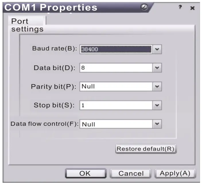
Change the serial port configuration to 38400-baud rate, 8 data bits, no parity bit, 1 stop bit, no data flow control, press the “OK” button, you have set up the Windows serial port Hyper Terminal.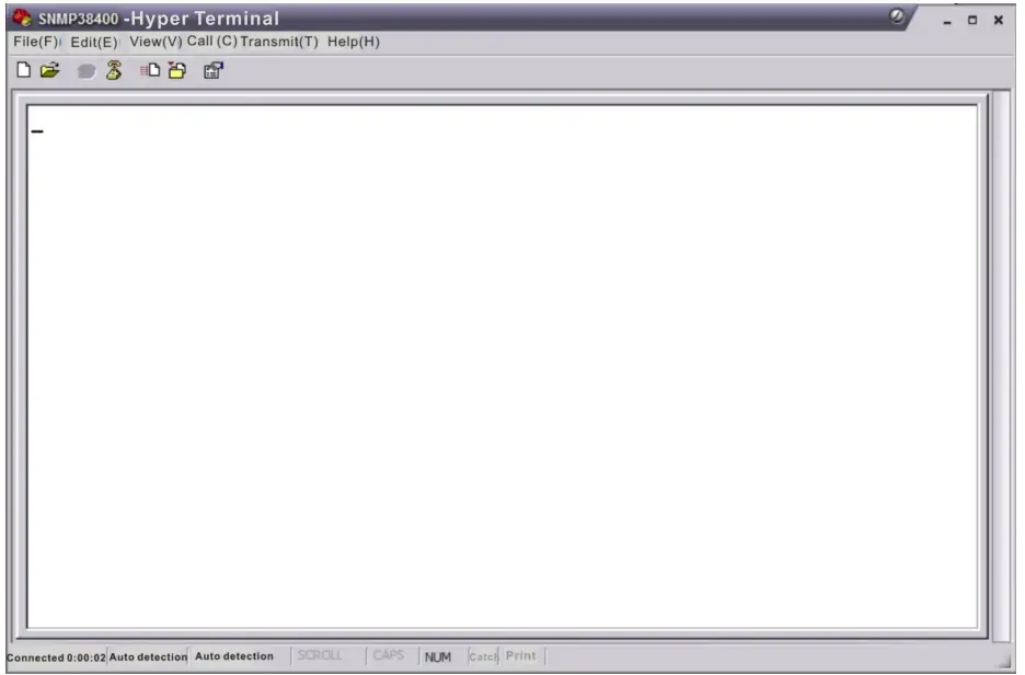
You can click “file save” menu to save this configuration of Hyper Terminal for later using.
Operating Parameters Configuration
Under the condition of power off, use the serial port lines to connect the RS232 port with the computer port. Open the Windows Hyper Terminal which you have set up.
Then turn on the power, you will see the page as follows. Enter the password to enter the configuration interface.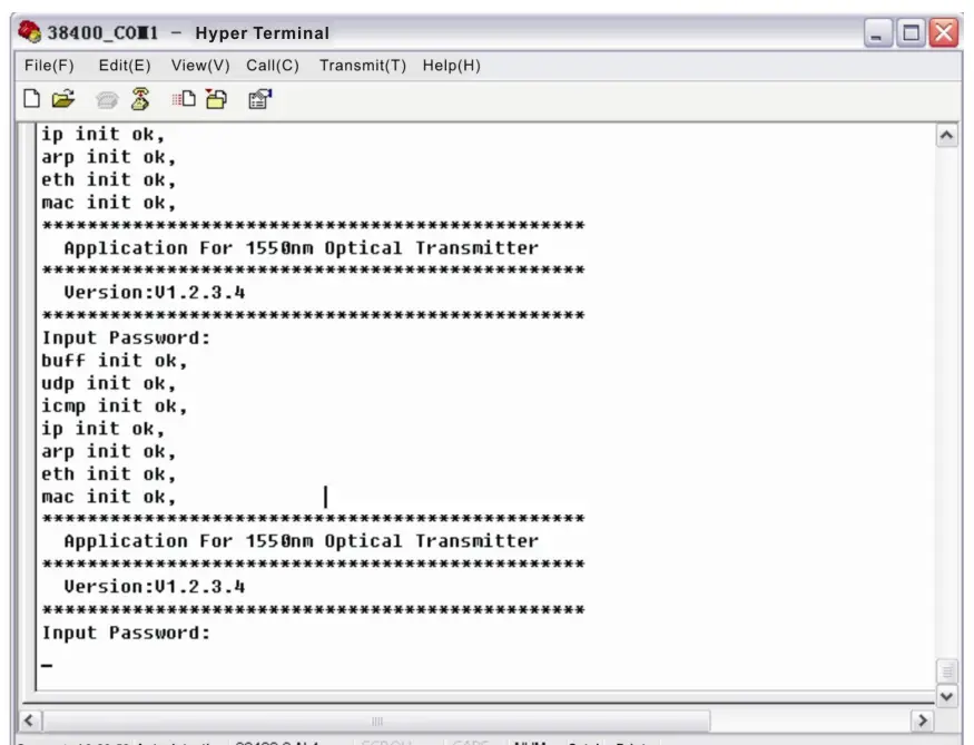
Enter the password, display the following screen: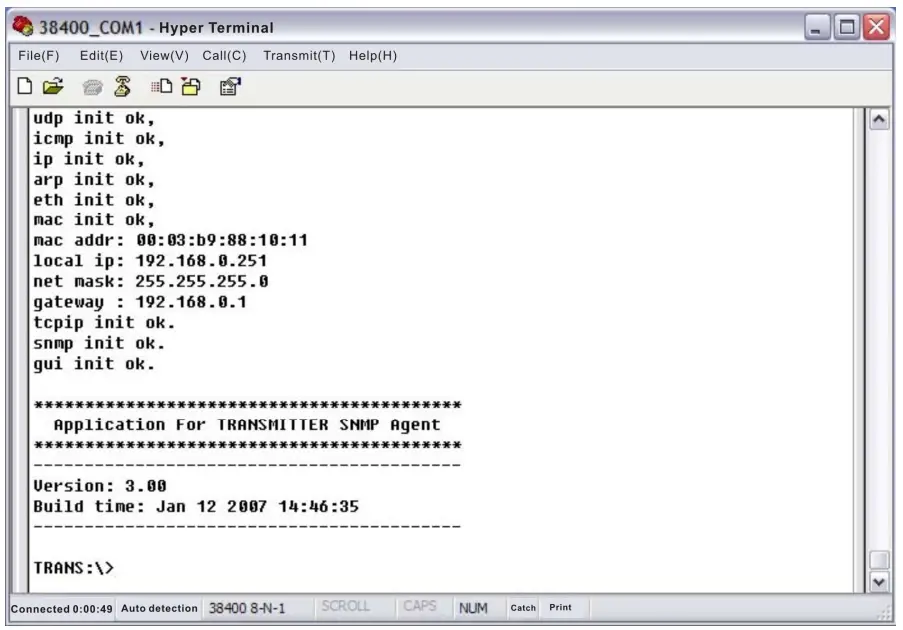
You can input your command in this page, and then configure the operating parameter of the application program.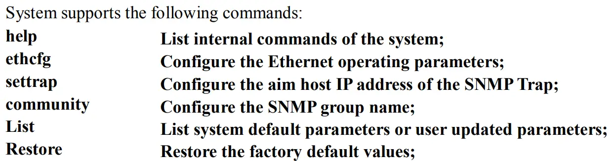
Specific using as follows:
help
This command shows current application program version, program name and the internal commands list of the system as follows: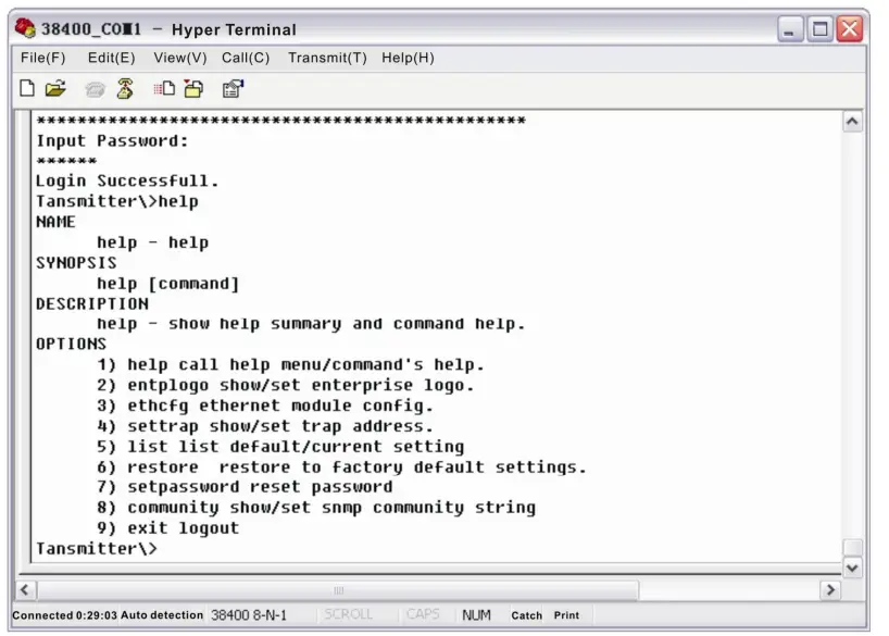
You can also use the “help” command to show help information of other commands, such as “help ethcfg”,ethcfg’s help information appears as follows: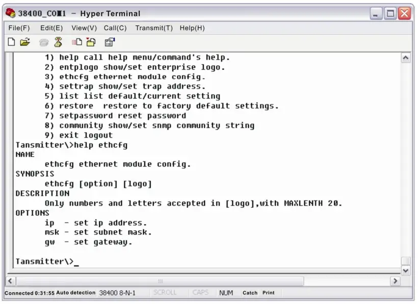
ethcfg
This command configures the Ethernet parameters, including IP address, subnet mask and gateway. You can refer to the help information for its using.
settrap
This command shows or modifies the aim host IP address list of the SNMP Trap, IP address of 0.0.0.0 and 255.255.255.255 don’t exist. SNMP Trap does not send to these two addresses.
community
This command configures the read-only group name and read-write group name. “Group name” is the concept of SNMP agreement like the password. Use the command “community ro” to configure the read-only, and “community rw” for the read-write. For example, input “community rw public”, “public” is the read-write group name. The group name for read-only and read-write are both “public” as the equipment default setting from factory.
Remote Monitoring: SNMP
LAN communication interface Adopt RJ45 standard connector, the pin definitions as follow: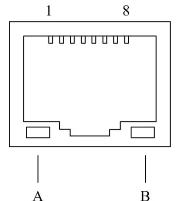
- TX+
- TX-
- RX+
- No Connect
- No Connect
- RX-
- No Connect
- No Connect
- A: Green indicator flashing means that the LAN port is sending data.
- B: Yellow indicator means that the network connection is normal.
SNMP basic background
Simple Network Management Protocol (SNMP) is an application layer protocol. It makes the management information between network devices exchange easier. It is part of the TCP / IP protocol group. SNMP enables the end-users to manage network performance, find and solve network problems, and arrange for future network upgrades. Management Information Base (MIB) is the organized hierarchical information set. Use SNMP to visit these MIB. They are composed of manageable information, and identified by the object identifier.
SNMP
Transmitter configuration of network communication When the transmitter initial work, the IP address and gateway are in the default state, you need to configure them. The configuration of initial state can be achieved through the RS-232 interface or the front panel keys. Other configurations see our 5.5 WEB Network Management section.
WEB Network Management
Open the IE browser, type the IP address and enter the interface as follows: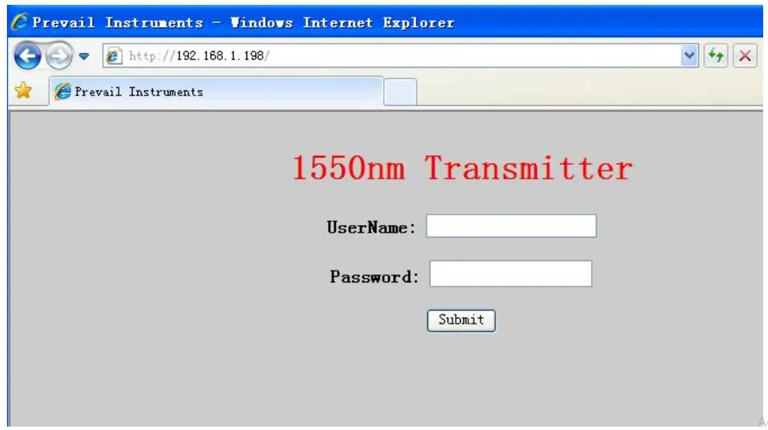
Type the user name admin and the password 123456 (factory default), enter the following interface: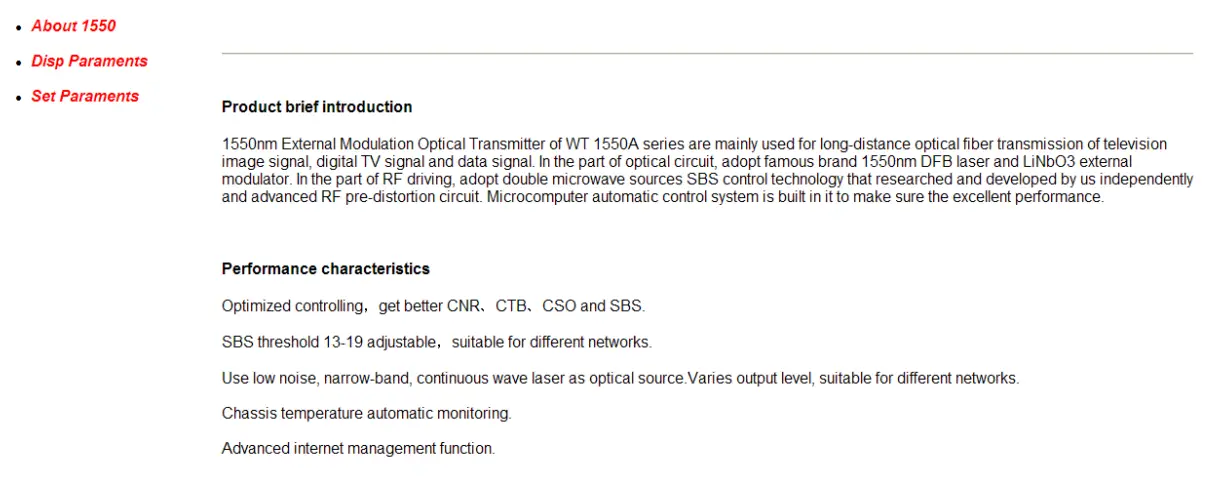
There are 3 sub-interfaces:
- About1550 interface: Mainly described the basic information of the equipment.
- Disp Paraments interface: Mainly described the display menu of the equipment.
- Set Paraments interface: Change the device parameters in this interface.
Click Set Paraments to enter Set Paraments interface as follows: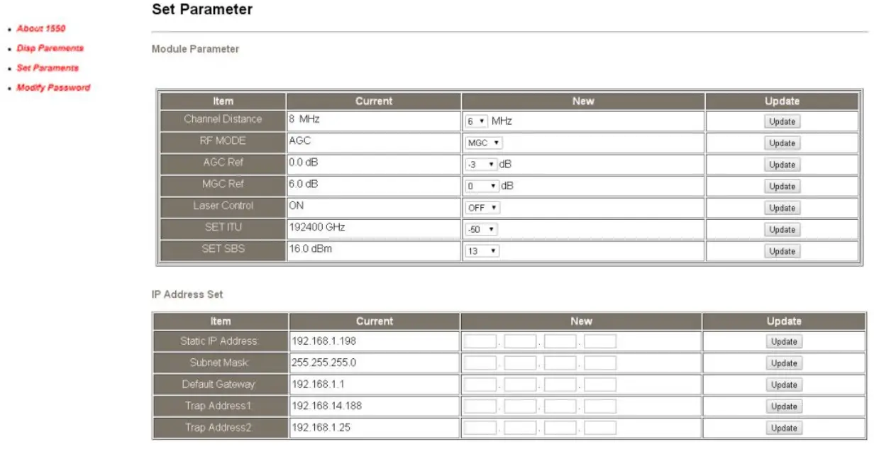
The Item and Items columns list the parameters that can be changed, the Current column lists the present parameter values, the New column can select or type the new parameter values, and the Update column can update the parameters. The steps to change the parameters: find the item in the Item column, select the new parameter values in the New column, and click the corresponding Update button to update the parameters. The change steps in the Items are the same, but finally need to click the Restart Device button to take effect.
Maintenance and Troubleshooting
Cleaning Fiber Optic Connectors
Dirty optical connectors are the leading source of poor performance in a broadband optical fiber network. Dirty optical connectors lead to optical signal loss and reflections, which in turn can seriously degrade signal-to-noise (SNR) performance and, in some cases, distortion performance. We recommend that you clean all mating fiber connectors before connecting them to an optical transmitter. In addition, if you suspect that the optical connector of equipment may have been exposed to contamination (by a dirty fiber cable connector, for example), you should properly clean the optical connector before connecting the optical fiber.
CAUTION: Improper cleaning of an optical connector can do more harm than good. Never spray a clean-air product onto the surface of an optical connector. Spraying air onto an optical connector can cause condensation on the connector surface, leaving water spots and trapping dust. Failing to wipe a connector on dry lens paper immediately after wiping on paper wet with isopropyl alcohol can also lead to condensation on the connector. Using low-grade cleaning paper or other cloth to wipe an optical connector can leave microscopic fibers on the optical connector Surface.
Cleaning Patch Cord or Pigtail Fiber Optical Connectors
To clean optical connectors, we recommend using a fiber optic connector cleaning cartridge (such as NTT Cletop). If a cleaning cartridge is not available, follow these steps.
To clean the optical connector of a patch cord or pigtail:
- Fold a piece of unused dry lens cleaning paper twice, for a four-ply thickness.
- Use a drop of high-grade isopropyl alcohol to wet part of the paper.
- Lay the connector on the lens cleaning paper with the tip touching the paper.
- In one continuous motion, pull the connector from the wet part of the paper to the dry part.
Troubleshooting
Should a problem occur, see if the symptoms are listed in Table 6-1. Table 6-1: Troubleshooting Solutions
| Indicator status | Alarm menu content | Fault phenomenon | Solution | |
| Power indicator is yellow |
Power Invalid |
LEFT (RIGHT) | The left (right) power is break down or the power cord is not plugged in | Plug in the left (right) power cord. If that does not correct the problem, contact Customer Service. Replace the power supply. |
| Power indicator is flash yellow | -5V Status +5V Status +12V Status -12V Status +24V Status | HIGH (LOW) HIGH (LOW) HIGH (LOW) HIGH (LOW) HIGH (LOW) | Power alarm menu shows one of the contents
The laser is off |
Contact Customer Service. |
|
RF indicator is flash red |
RF IN Status |
LOW (HIGH) |
RF input is low (high) | Verify the optical transmitter is operating within the proper input level threshold range (78-96dBµV). If that does not solve the problem, contact Customer Service. |
| CSO Initialization failed | CSO nonlinearity indexes are poor | Disconnect the RF connection, wait 10 seconds before reconnecting the RF signal. | ||
| Laser indicator is | Laser Bias | HIGH | The laser is off | Contact Customer Service. |
Disclaimer
We reserve the right to change any products described herein at any time, and without prior notice. We assume no responsibility or liability arising from the use of the products described herein, except as expressly agreed to in writing by us. The use and purchase of this product does not convey a license under any patent rights, copyrights, trademark rights, or any intellectual property rights of us. Nothing hereunder constitutes a representation or warranty that using any products in the manner described herein will not infringe any patents of third parties.


