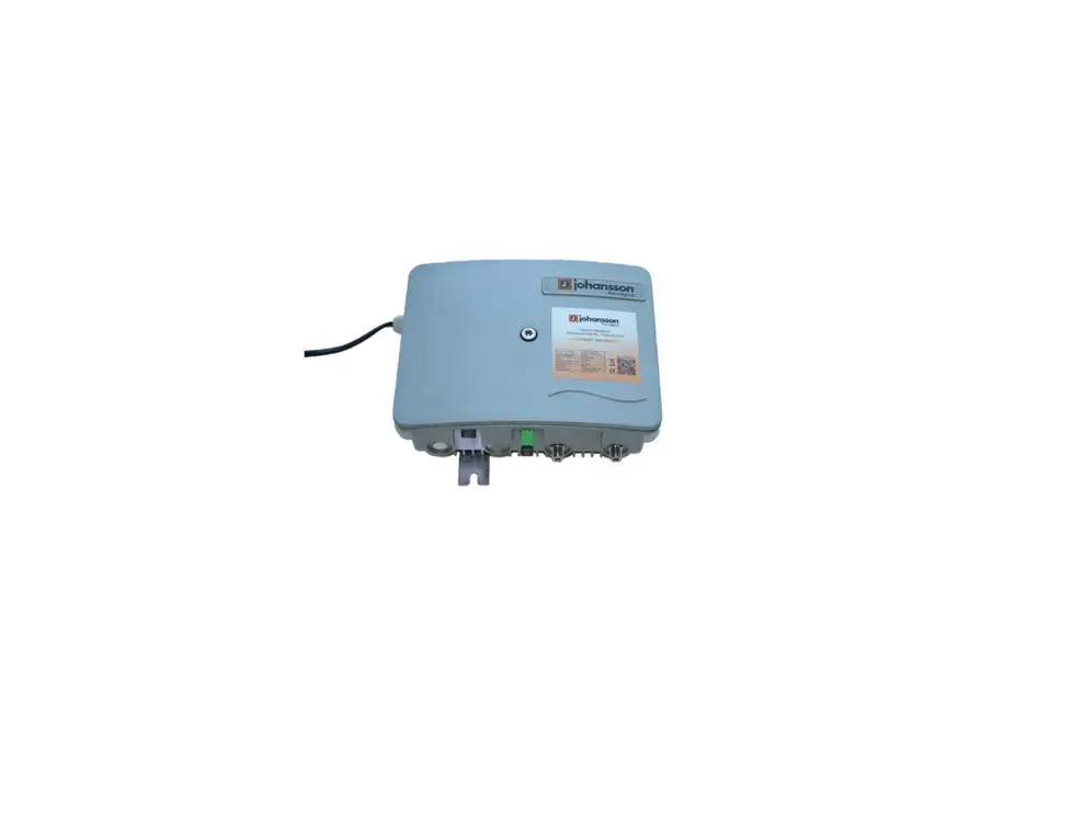
johansson 4000 Optical Headend Transmitter
No part of this manual may be copied, reproduced, transmitted, transcribed or translated into any language without permission.
Unitron reserves the right to change the specifications of the hardware and software described in these manuals at any time.
Unitron cannot be held liable for any damages resulting from the use of this product. Specifications are subject to change without notice. 8/20
© Unitron NV – Frankrijklaan 27 – B-8970 Poperinge – Belgium
T +32 57 33 33 63 F +32 57 33 45 24
[email protected]
www.unitrongroup.com
INTRODUCTION
Product description
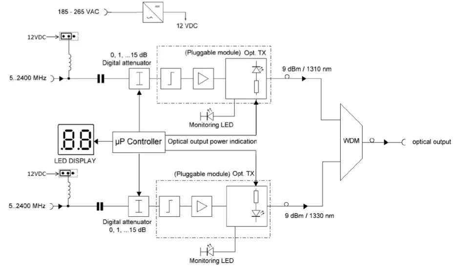
The 4000 Optical Compact Headend converts 2 wideband satellite inputs into 2 wavelengths (1310nm – 1330nm) and puts them on 1 optical feed. The output signal is strong enough to support huge installations, with up to 128 passive splits. The 4001 Optical Compact Headend converts 1 input to 1550nm optical wavelength.
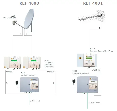
REF 4000: OPTICAL HEADEND TRANSMITTER 2 WAVELENGTHS (1310 NM – 1330 NM)
- 2 wideband V/H inputs
- frequency range: 5 – 2400 MHz
- 1 optical output (wavelengths: 1310nm (V) – 1330nm(H))
- 9 dBm output power
REF 4001: OPTICAL HEADEND TRANSMITTER 1 WAVELENGTH (1550 NM)
- 1 wideband input
- frequency range: 5-2400 MHz
- 1 optical output (wavelength 1550nm)
- 9 dBm output power
- optical input for loopthrough (from ref. 4000)
Package contents
- 1x Optical Headend (REF 4000 or REF 4001)
INSTALLATION OF THE HARDWARE
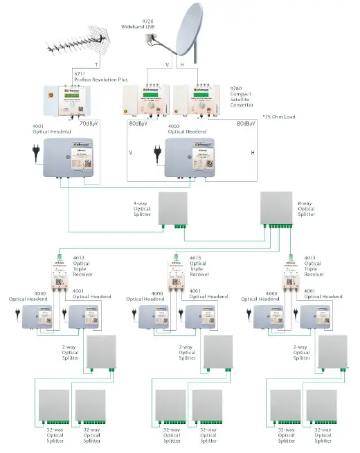
General set-up
Combining the REF 4000 and the REF 4001 with the LOOPTHROUGH
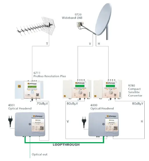
Cascading the Headends
The optical output signal can be split passively up to 128 times, or even more when you cascade the headends.
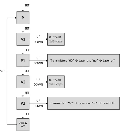
CONFIGURATION OF THE MODULE
- To configure the headend, remove the central bolt and lift the top lid
- The settings will appear on the LED display.
- Use the buttons (SET-DOWN-UP) in the top right corner of the device.
- Follow the steps below to configure the headend.
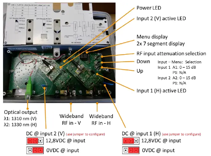
REF 4000 internal product overview
REF 4001 internal product overview 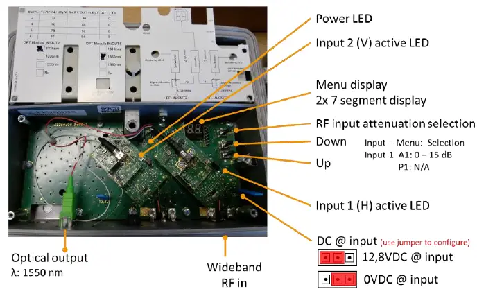
BLOCK DIAGRAM
TECHNICAL SPECIFICATIONS
| REF 4000 | REF 4001 | ||
| Inputs | – | 2 RF | 1 RF + 1 optical (loopthrough from ref. 4000) |
| Outputs | – | 1 Optical | |
| Optical wavelength | nm | 1310 – 1330 | 1550 |
| Frequency range | MHz | 5 – 2400 | |
| Optical output power | dBm | +9 (per wavelength) | |
| Ripple | dB | +/- 2.5 | |
| Optimal input level | dBµV | SAT: 80 per Transponder TERR: 70 per MUX | |
| Input attenuator | dB | 0 – 15 | |
| Laser type | – | DFB | |
| Laser LED control | – | Green LED on | |
| LNB power supply | – | 12.8V / max. 240 mA | |
| Optical connectors | – | SC/APC | |
| RF connectors | – | F-female | |
| Power consumption | W | 9 | 6 |
| Power supply | VAC | 200 – 240 | |
| Operating temperature range | °C | -20 to +55 | |
| Protection class | – | IP 50 | |
| Dimensions | mm | 225 x 190 x 86 | |
| Weight | kg | 1.8 | |
SAFETY INSTRUCTIONS
Read these instructions carefully before connecting the unit
To prevent fire, short circuit or shock hazard:
- Do not expose the unit to rain or moisture.
- Install the unit in a dry location without infiltration or condensation of water.
- Do not expose it to dripping or splashing.
- Do not place objects filled with liquids, such as vases, on the apparatus.
- If any liquid should accidentally fall into the cabinet, disconnect the power plug.
To avoid any risk of overheating:
- Install the unit in a well aery location and keep a minimum distance of 15 cm around the apparatus for sufficient ventilation
- Do not place any items such as newspapers, table-cloths, curtains, on the unit that might cover the ventilation holes.
- Do not place any naked flame sources, such as lighted candles, on the apparatus
- Do not install the product in a dusty place
- Use the apparatus only in moderate climates (not in tropical climates)
- Respect the minimum and maximum temperature specifications
To avoid any risk of electrical shocks:
- Connect apparatus only to socket with protective earth connection.
- The mains plug shall remain readily operable
- Pull out power plug to make the different connections of cables
- To avoid electrical shock, do not open the housing of adapter.
Maintenance
Only use a dry soft cloth to clean the cabinet.
Do not use solvent
For repairing and servicing refer to qualified personnel. Dispose according your local authority’s recycling processes
CONDITIONS OF WARRANTY
Unitron N.V. warrants the product as being free from defects in material and workmanship for a period of 24 months starting from the date of production indicated on it. See note below.
If during this period of warranty the product proves defective, under normal use, due to defective materials or workmanship, Unitron N.V, at its sole option, will repair or replace the product. Return the product to your local dealer for reparation.
THE WARRANTY IS APPLIED ONLY FOR DEFECTS IN MATERIAL AND WORKMANSHIP AND DOES NOT COVER DAMAGE RESULTING FROM:
- Misuse or use of the product out of its specifications,
- Installation or use in a manner inconsistent with the technical or safety standards inforce in the country where the product is used,
- Use of non-suitable accessories (power supply, adapters…),
- Installation in a defect system,
- External cause beyond the control of Unitron N.V. such as drop, accidents,lightning, water, fire, improper ventilation…
THE WARRANTY IS NOT APPLIED IF
- Production date or serial number on the product is illegible, altered, deleted orremoved.
- The product has been opened or repaired by a non-authorized person.
NOTE
Date of production can be found in the product’s serial number code. The format will either be “YEAR W WEEK” (e.g., 2017W32 = year 2017 week 32) or “YYWW” (e.g., 1732 = year 2017 week 32).
UNITRON NV Frankrijklaan 27 B-8970 Poperinge
Belgium
T +32 57 33 33 63 F +32 57 33 45 24
[email protected]
www.unitrongroup.com
Dovozce:
Elektro HERINK s.r.o.
Wenzigova 79/8
301 00 Plzeň
Tel.: 377 222 255
Mobil: 606 615 292
[email protected]


