![]() User Manual
User Manual
Optical Convertor
Ref. 4031 – 4032 – 4033 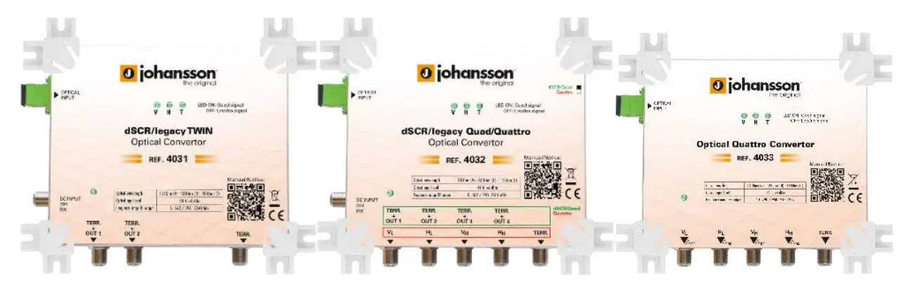
No part of this manual may be copied, reproduced, transmitted, transcribed or translated into any language without permission.
Unitron reserves the right to change the specifications of the hardware and software described in these manuals at any time.
Unitron cannot be held liable for any damages resulting from the use of this product. Specifications are subject to change without notice. 2/22
© Unitron NV – Frankrijklaan 27 – B-8970 Poperinge – Belgium
T +32 57 33 33 63 F +32 57 33 45 24
[email protected]
www.unitrongroup.com
INTRODUCTION
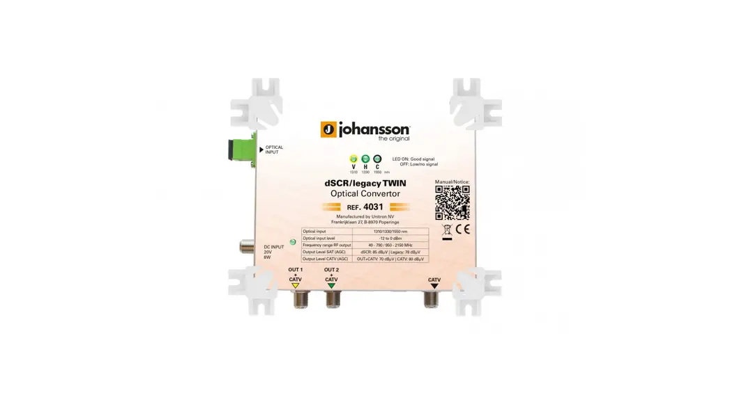
Product description REF 4031
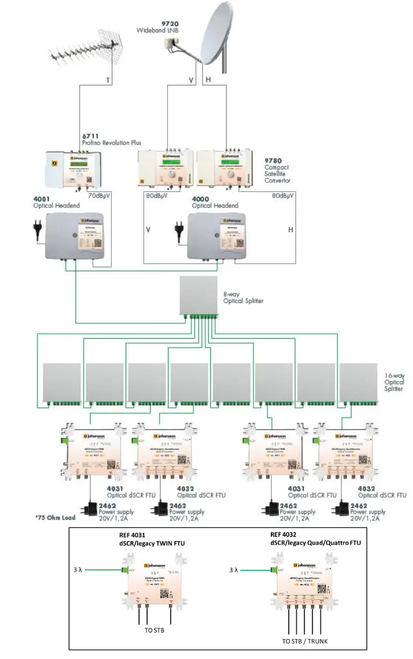
DSCR/LEGACY TWIN FTU
- optical wavelengths: 1310nm (V) + 1330nm (H) + 1550nm (T)
- optical input level: -14 to +6 dBm
- 3 outputs (2 dSCR/legacy/TERR. + 1 TERR.)
- AGC on all output ports
- signal quality indicator per wavelength
- Sky compatible
- can be used in systems with up to 128 splits
Product description REF 4032
DSCR/LEGACY QUAD/QUATTRO FTU
- optical wavelengths: 1310nm (V) + 1330nm (H) + 1550nm (T)
- optical input level: -14 to +6 dBm
- 5 outputs
o Quad mode: 4 x dSCR/Legacy + TERR.
o Quattro mode: Vl, Hl, Vh, Hh, TERR (serves as satellite output trunk) - AGC on all output ports
- signal quality indicator per wavelength
- Sky compatible
- can be used in systems with up to 128 splits
Product description REF 4033
QUATTRO FTU
- optical wavelengths: 1310nm (V) + 1330nm (H) + 1550nm (T)
- optical input level: -14 to +4 dBm
- 5 outputs: Quattro mode: Vl, Hl, Vh, Hh, TERR
- AGC on all output ports
- signal quality indicator per wavelength
- Can be used in systems with up to 128 splits
INSTALLATION OF THE HARDWARE
TECHNICAL SPECIFICATIONS REF 4031
| Optical inputs | – | 1 |
| RF outputs | – | 3 (2 dSCR/Legacy/TERR. + 1 TERR.) |
| Optical wavelengths | nm | 1310 – 1330 – 1550 |
| Frequency range | MHz | 40 – 790 / 950 — 2150 (REF 4031) 40 – 862 / 950 — 2150 (REF 4031 MC) |
| Optical input level | dBm | -14 to +6 |
| Signal indicator | – | Green LED per wavelength |
| dCSS/dSCR UBs | – | 2 x 16 |
| Output level dSCR (AGC) | dBpV | 85 |
| Output level Legacy (AGC) | dBpV | 80 |
| Output level TERR (AGC) | dBpV | 70 |
| Return loss | dB | 10 |
| Optical connector type | – | SC / APC |
| Output connector type | – | 75 ohm F type (female)* |
| Band and polarity selection | – | DiSEqC 1.0 (unidirectional) DiSEqC 2.0 (bidirectional) Standard EN50494/EN50607 SKY UK protocol Universal LNB Voltage & Tone |
| Power consumption | W | 9 |
| Power supply via output (STB) | VDC | 12 – 20 |
| Power supply via DC IN | VDC | 20 |
| Power indicator | – | Green LED |
| Operating temperature range | °C | -20 to +55 |
| Dimensions | mm | 166 x 136 x 25 |
| Weight | kg | 0.310 |
*: Unused ports needs to be terminated with 75 Ohm DC-blocked terminator
| 4032 Quattro mode | 1 4032 Quad mode | ||
| Optical inputs | – | 1 | |
| RF outputs | – | VL, HL, VH, HH, T | 4 x dSCR/legacy + TERR. |
| Optical wavelengths | nm | 1310 – 1330 – 1550 | |
| Frequency range | MHz | 40 – 790 / 950 — 2150 (REF 4032) 40 – 862 / 950 — 2150 (REF 4032MC) | |
| Optical input level | dBm | -14 to +6 | |
| Signal indicator | – | Green LED per wavelength | |
| dCSS/dSCR UBs | – | – | 4 x 16 |
| Output level dSCR (AGC) | dBpV | 85 | |
| Output level Legacy (AGC) | dBpV | 80 | |
| Output level TERR (AGC) | dBpV | 80 | 70 |
| Return loss | dB | 10 | |
| Input connector type | – | SC / APC | |
| Output connector type | – | 75 ohm F type (female)* | |
| Band and polarity selection | – | DiSEqC 1.0 (unidirectional) DiSEqC 2.0 (bidirectional) Standard EN50494/EN50607 SKY UK protocol Universal LNB Voltage & Tone | |
| Power consumption | W | 12 | |
| Power supply via output (STB) | VDC | 12 – 20 | |
| Power supply via DC IN | VDC | 20 | |
| Power indicator | – | Green LED | |
| Operating temperature range | °C | -20 to +55 | |
| Dimensions | mm | 166 x 136 x 25 | |
| Weight | kg | 0.500 | |
*: Unused ports needs to be terminated with 75 Ohm DC-blocked terminator
CHANNEL PLANS
REF 4031 and REF 4032
| Sky UK | EN50607 | EN50494 | |||
| UB | FREQ | UB | FREQ | UB | FREQ |
| 1680 | 985 | 1210 | |||
| 9 | 1280 | 6 | 1050 | 1420 | |
| 11 | 1380 | 7 | 1115 | 3 | 1680 |
| 14 | 1480 | 8 | 1275 | 4 | 2040 |
| 15 | 980 | 9 | 1340 | ||
| 16 | 1030 | 10 | 1485 | ||
| 17 | 1080 | 11 | 1550 | ||
| 18 | 1130 | 12 | 1615 | ||
| 19 | 1530 | 13 | 1745 | ||
| 20 | 1580 | 14 | 1810 | ||
| 21 | 1630 | 15 | 1875 | ||
| 22 | 1730 | 16 | 1940 | ||
| 23 | 1780 | ||||
| 24 | 1830 | ||||
| 25 | 1880 | ||||
| 26 | 1930 | ||||
REF 4031MC and REF 4032MC
| Multichoice (MC) | |||
| EN50494 | EN50607 | ||
| UB | FREQ | UB | FREQ |
| 1 | 1210 | 1 | 1210 |
| 2 | 1420 | 2 | 1420 |
| 3 | 1680 | 3 | 1680 |
| 4 | 2040 | 4 | 2040 |
| 5 | 1006 | 5 | 1006 |
| 6 | 1057 | 6 | 1057 |
| 7 | 1108 | 7 | 1108 |
| 8 | 1159 | 8 | 1159 |
| 9 | 126i | ||
| 10 | 1312 | ||
| 11 | 1363 | ||
| 12 | 1471 | ||
| 13 | 1522 | ||
| 14 | 1573 | ||
| 15 | 1624 | ||
| 16 | 1731 | ||
SAFETY INSTRUCTIONS
![]() Read these instructions carefully before connecting the unit
Read these instructions carefully before connecting the unit
![]() To prevent fire, short circuit or shock hazard:
To prevent fire, short circuit or shock hazard:
- Do not expose the unit to rain or moisture.
- Install the unit in a dry location without infiltration or condensation of water.
- Do not expose it to dripping or splashing.
- Do not place objects filled with liquids, such as vases, on the apparatus.
- If any liquid should accidentally fall into the cabinet, disconnect the power plug.
![]() To avoid any risk of overheating:
To avoid any risk of overheating:
- Install the unit in a well aery location and keep a minimum distance of 15 cm around the apparatus for sufficient ventilation
- Do not place any items such as newspapers, table-cloths, curtains, on the unit that might cover the ventilation holes.
- Do not place any naked flame sources, such as lighted candles, on the apparatus
- Do not install the product in a dusty place
- Use the apparatus only in moderate climates (not in tropical climates)
- Respect the minimum and maximum temperature specifications
![]() To avoid any risk of electrical shocks:
To avoid any risk of electrical shocks:
- Connect apparatus only to socket with protective earth connection.
- The mains plug shall remain readily operable
- Pull out power plug to make the different connections of cables
- To avoid electrical shock, do not open the housing of adapter.
Maintenance
![]() Only use a dry soft cloth to clean the cabinet.
Only use a dry soft cloth to clean the cabinet.![]() Do not use solvent
Do not use solvent![]() For repairing and servicing refer to qualified personnel.
For repairing and servicing refer to qualified personnel.
Dispose according your local authority’s recycling processes
CONDITIONS OF WARRANTY
Unitron N.V. warrants the product as being free from defects in material and workmanship for a period of 24 months starting from the date of production indicated on it. See note below.
If during this period of warranty the product proves defective, under normal use, due to defective materials or workmanship, Unitron N.V, at its sole option, will repair or replace the product. Return the product to your local dealer for reparation.
THE WARRANTY IS APPLIED ONLY FOR DEFECTS IN MATERIAL AND WORKMANSHIP AND DOES NOT COVER DAMAGE RESULTING FROM:
- Misuse or use of the product out of its specifications,
- Installation or use in a manner inconsistent with the technical or safety standards in force in the country where the product is used,
- Use of non-suitable accessories (power supply, adapters…),
- Installation in a defect system,
- External cause beyond the control of Unitron N.V. such as drop, accidents, lightning, water, fire, improper ventilation…
THE WARRANTY IS NOT APPLIED IF
- Production date or serial number on the product is illegible, altered, deleted or removed.
- The product has been opened or repaired by a non-authorized person.
NOTE
Date of production can be found in the product’s serial number code. The format will either be “YEAR W WEEK” (e.g., 2017W32 = year 2017 week 32) or “YYWW” (e.g., 1732 = year 2017 week 32).
 www.unitrogroup.com
UNITRON NV
Frankrijklaan 27
B-8970 Poperinge
Belgium
T +32 57 33 33 63
F +32 57 33 45 24
[email protected]
www.unitrongroup.com


