CompuLab SBC-IOT-IMX8PLUS Industrial Raspberry Pi IoT Gateway User Guide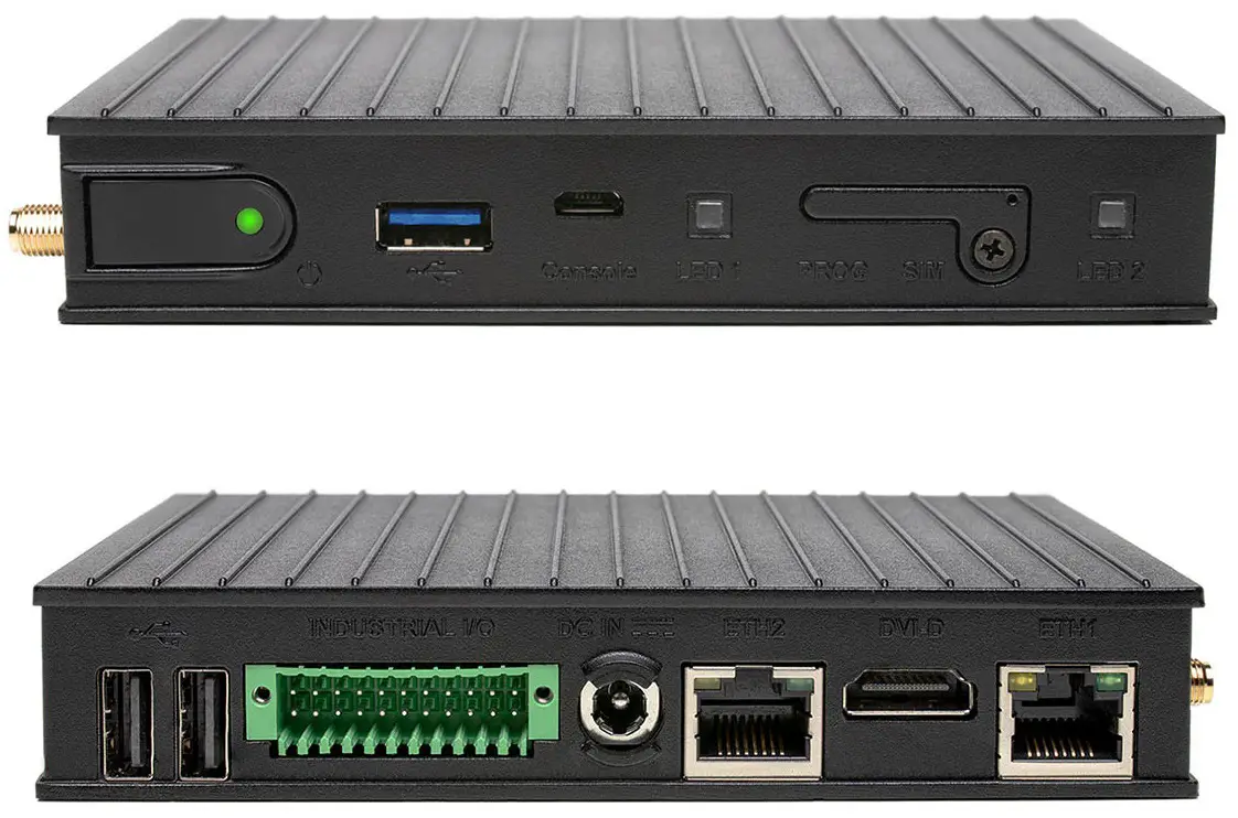
INTRODUCTION
About This Document
This document is part of a set of documents providing information necessary to operate and program Compulab SBC-IOT-IMX8PLUS.
Related Documents
For additional information not covered in this manual, please refer to the documents listed in Table 2.
Table 2 Related Documents
| Document | Location |
| SBC-IOT-IMX8PLUS resources | https://www.compulab.com/products/sbcs/sbc-iot-imx8plus-nxp-i- mx8m-plus-internet-of-things-single-board-computer/#devres |
OVERVIEW
Highlights
- NXP i.MX8M-Plus CPU, quad-core Cortex-A53
- Up to 8GB RAM and 128GB eMMC
- LTE/4G modem, WiFi 802.11ax, Bluetooth 5.3
- 2x LAN, USB3.0, 2x USB2.0 and CAN bus
- Up-to 3x RS485 | RS232 and digital I/O
- Secure boot and Hardware Watchdog
- Designed for reliability and 24/7 operation
- Wide temperature range of -40C to 80C
- Input voltage range of 8V to 36V and PoE client
- Debian Linux and Yocto Project
Specifications
Table 3 CPU Core, RAM, and Storage
| Feature | Specifications |
| CPU | NXP i.MX8M Plus Quad, quad-core ARM Cortex-A53, 1.8GHz |
| NPU | AI/ML Neural Processing Unit, up to 2.3 TOPS |
| Real-Time Co-processor | ARM Cortex-M7, 800Mhz |
| RAM | 1GB – 8GB, LPDDR4 |
| Primary storage | 16GB – 128GB eMMC flash, soldered on-board |
Table 4 Network
| Feature | Specifications |
| LAN | 2x 1000Mbps Ethernet portx, RJ45 connectors |
| WiFi and Bluetooth | 802.11ax WiFi and Bluetooth 5.3 BLE Implemented with Intel WiFi 6E AX210 module 2x 2.4GHz / 5GHz rubber duck antennas |
| Cellular | 4G/LTE CAT4 cellular module, Quectel EC25-E/A Cellular rubber duck antenna |
| SIM card socket | |
| GNSS | GPS Implemented with Quectel EC25 module |
Table 5 Display and Graphics
| Feature | Specifications |
| Display Output | DVI-D, up to 1080p60 |
| GPU and Video | GC7000UL GPU1080p60 HEVC/H.265, AVC/H.264* only with C1800QM CPU option |
Table 6 I/O and System
| Feature | Specifications |
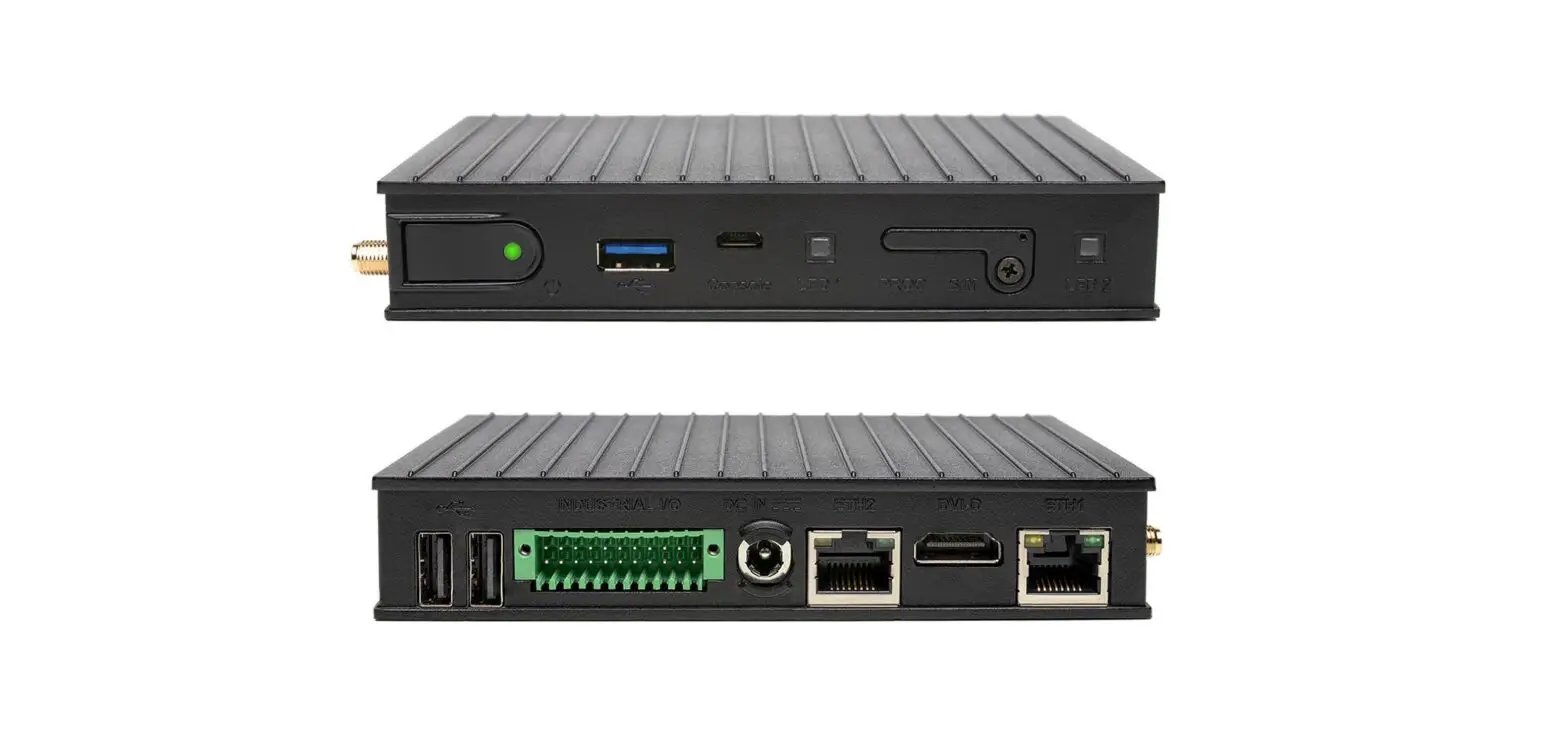
| USB | 2x USB2.0 ports, type-A connectors (back panel) |
| 1x USB3.0 port, type-A connector (front panel) | |
| RS485 / RS232 | Up-to 3x RS485 (half-duplex) | RS232 ports Isolated, terminal-block connector |
| CAN bus | 1x CAN bus portIsolated, terminal-block connector |
| Digital I/O | 4x digital outputs + 4x digital inputsIsolated, 24V compliant with EN 61131-2, terminal-block connector |
| Debug | 1x serial console via UART-to-USB bridge, micro-USB connector |
| Support for NXP SDP/UUU protocol, micro-USB connector | |
| Expansion | Expansion connector for add-on boards LVDS, SDIO, USB, SPI, I2C, GPIOs |
| Security | Secure boot, implemented with i.MX8M Plus HAB module |
| LEDs | 2x general purpose dual-color LEDs |
| RTC | Real time clock operated from on-board coin-cell battery |
| Watchdog | Hardware watchdog |
| PoE | Support for PoE (powered device) |
Table 7 Electrical, Mechanical and Environmental
| Supply Voltage | Unregulated 8V to 36V |
| Dimensions | 132 x 84 x 25mm |
| Heat-plate | Aluminum heat-plate, 130mm x 80mm * only with “H” configuration option |
| Cooling | Passive cooling, fanless design |
| Weight | 450 gram |
| MTTF | 2000,000 hours |
| Operation temperature | Commercial: 0° to 60° C Extended: -20° to 60° C Industrial: -40° to 80° C |
CORE SYSTEM COMPONENTS
NXP i.MX8M Plus SoC
The i.MX8M Plus processors feature advanced implementation of a quad ARM® Cortex®-A53 core, which operates at speeds of up to 1.8 GHz. A general purpose Cortex®-M7 core processor enables low-power processing.
Figure 1 i.MX8M Plus Block Diagram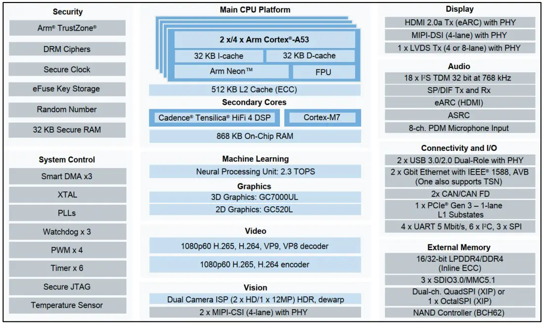
System Memory
DRAM
SBC-IOT-IMX8PLUS is available with up to 8GB of on-board LPDDR4 memory.
Primary Storage
SBC-IOT-IMX8PLUS features up to 128GB of soldered on-board eMMC memory for storing the bootloader and operating system (Kernel and root filesystem). The remaining eMMC space is used to store general-purpose (user) data.
WiFi and Bluetooth
SBC-IOT-IMX8PLUS can be optionally assembled with the Intel WiFi 6 AX210 module providing 2×2 WiFi 802.11ax and Bluetooth 5.3 interfaces. AX210 module is installed into M.2 socket (P22).
WiFi and Bluetooth antenna connections are available via two on-board MHF4 connectors. SBC-IOT-IMX8PLUS is supplied with two MHF4-to-RP-SMA cables and two 2.4GHz / 5GHz rubber duck antennas.
Cellular and GPS
SBC-IOT-IMX8PLUS cellular interface is implemented with a mini-PCIe cellular modem module and a nano-SIM socket. To set up SBC-IOT-IMX8PLUS for cellular functionality, install an active SIM card into nano-SIM socket U10. The cellular module should be installed into mini PCIe socket P3.
The cellular modem module also implements GNNS / GPS.
Modem antenna connections are available via on-board MHF connectors. SBC IOT IMX8PLUS is supplied with two MHF-to-SMA cables and one cellular rubber-duck antenna.
CompuLab supplies SBC-IOT-IMX8PLUS with the following cellular modem options:
- 4G/LTE CAT4 cellular module, Quectel EC25-E (EU bands)
- 4G/LTE CAT4 cellular module, Quectel EC25-A (US bands)
Figure 2 cellular modem and SIM card sockets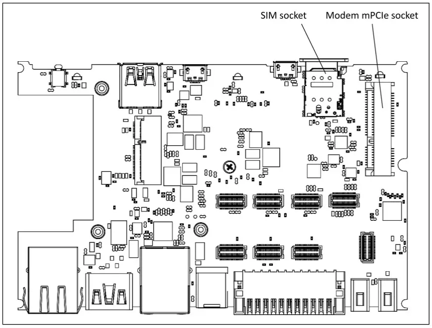
Ethernet
SBC-IOT-IMX8PLUS incorporates two Ethernet ports implemetned with i.MX8M Plus internal MACs and two Realtek RTL8211 PHYs
ETH1 is available on connector P13; ETH2 is available on connector P14.
ETH2 port features optional POE 802.3af powered device capability.
NOTE: ETH2 port features PoE powered device capability only when the unit is ordered with the ‘POE’ configuration option.
USB
USB3.0
SBC-IOT-IMX8PLUS features one USB3.0 host port routed to front panel USB connector J8. USB3.0 port is implemented directly with the native i.MX8M Plus port.
USB2.0
SBC-IOT-IMX8PLUS features two external USB2.0 host ports. The ports are routed to back panel USB connectors P17 and P18. All USB2.0 ports are implemented with MicroChip USB2514 USB hub. 3.7 CAN bus SBC-IOT-IMX8PLUS features one CAN 2.0B port implemented with i.MX8M Plus CAN controller. CAN bus signals are routed to industrial I/O connector P8. For pin-out details please refer to section 5.4.
Serial Debug Console
SBC-IOT-IMX8PLUS features a serial debug console via UART-to-USB bridge over micro USB connector. CP2104 UART-to-USB bridge is interfaced with i.MX8M Plus UART port. CP2104 USB signals are routed to micro USB connector P20, located on the front panel.
Display Output
SBC-IOT-IMX8PLUS features DVI-D interface routed to standard HDMI connector. Display output interface support resolutions of up-to 1920 x 1080.
USB Programming Port
SBC-IOT-IMX8PLUS features a USB programming interface that can be used for device recovery using the NXP UUU utility.
USB programming interface is routed to the front panel connector P16.
When a host PC is connected with a USB cable to the USB programming connector, SBC-IOTIMX8PLUS disables normal boot from eMMC and enters Serial Downloader boot mode.
I/O Expansion Socket
SBC-IOT-IMX8PLUS expansion interface is available on M.2 Key-E socket P12. The expansion connector allows integration of custom I/O add-on boards into SBC-IOT IMX8PLUS. The expansion connector features embedded interfaces such as LVDS, I2C, SPI, USB and SDIO.
Industrial I/O (IE modules)
SBC-IOT-IMX8PLUS features 4 industrial I/O (IE) slots that can be fitted with up-to 4 different I/O modules. Each IE slot is isolated from SBC-IOT-IMX8PLUS. I/O slots A,B,C can be fitted with RS232 or RS485 I/O modules. I/O slot D can only be fitted with a digital I/O (4x DI, 4x DO) module.
Table 8 Industrial I/O – functions and ordering codes
| I/O slot A | I/O slot B | I/O slot C | I/O slot D | |
| RS-232 (2-wire) | FARS2 | FBRS2 | FCRS2 | – |
| RS-485 (half-duplex) | FARS4 | FBRS4 | FCRS4 | – |
| Digital I/O(4x DI, 4x DO) | – | – | – | FDIO |
Combination examples:
- For 2x RS485 the ordering code will be SBC-IOTIMX8PLUS-…-FARS4 FBRS4-…
- For 1x RS232 + 1x RS485 + digital I/O the ordering code will be SBC IOTIMX8PLUS-…-FARS2- FBRS4-FDIO-…
Certain I/O combinations may also be implemented with on-board SMT components.
Industrial I/O signals are routed to a 2×11 terminal block on the SBC-IOT IMX8PLUS back panel. For connector pin-out please refer to section 5.4.
IE-RS485
RS485 function is implemented with MAX13488 transceiver interfaced with i.MX8M Plus UART ports. Key characteristics:
- 2-wire, half-duplex
- Galvanic isolation from the main unit
- Programmable baud rate of up to 3Mbps
- Software controlled 120ohm termination resistor
IE-RS232
RS232 function is implemented with MAX3221 (or compatible) transceiver interfaced with i.MX8M Plus UART ports. Key characteristics:
- RX/TX only
- Galvanic isolation from the main unit
- Programmable baud rate of up to 250kbps
Digital inputs and outputs
Four digital inputs are implemented with the CLT3-4B digital termination following EN 61131-2. Four digital outputs are implemented with the VNI4140K solid-state relay following EN 61131-2. Key characteristics:
- External supply voltage up to 24V
- Galvanic isolation from the main unit and other I/O modules
- Digital outputs maximal output current – 0.5A per channel
Figure 3 Digital output – typical wiring example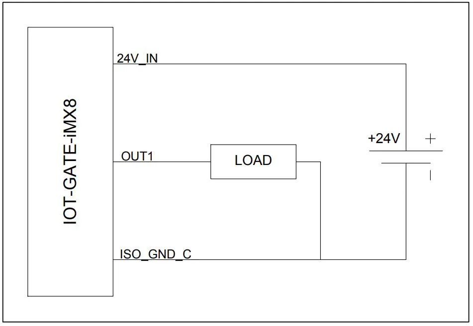
Figure 4 Digital input – typical wiring example
SYSTEM LOGIC
Power Subsystem
Power Rails
SBC-IOT-IMX8PLUS is powered with a single power rail with an input voltage range of 8V to 36V.
When SBC-IOT-IMX8PLUS is assembled with the “POE” option it can also be powered through ETH2 connector from a 802.3at Type 1 PoE source.
Power Modes
SBC-IOT-IMX8PLUS supports three hardware power modes
Table 9 Power modes
| Power Mode | Description |
| ON | All internal power rails are enabled. Mode entered automatically when the main power supply is connected. |
| OFF | CPU core power rails are off. All peripheral power rails are off. |
| Sleep | DRAM is maintained in self-refresh. Most CPU core power rails are off. Most of the peripheral power rails are off. |
RTC Back-Up Battery
SBC-IOT-IMX8PLUS features a 120mAh coin cell lithium battery, which maintains the on-board RTC whenever the main power supply is not present.
Real-Time Clock
SBC-IOT-IMX8PLUS RTC is implemented with the AM1805 real-time clock (RTC) chip. The RTC is connected to the i.MX8M Plus SoC using I2C interface at address 0xD2/D3. SBC IOT-IMX8PLUS back-up battery keeps the RTC running to maintain clock and time information whenever the main power supply is not present.
Hardware Watchdog
SBC-IOT-IMX8PLUS watchdog function is implemented with the i.MX8M Plus watchdog.
INTERFACES AND CONNECTORS
Connector Locations
Panel Connectors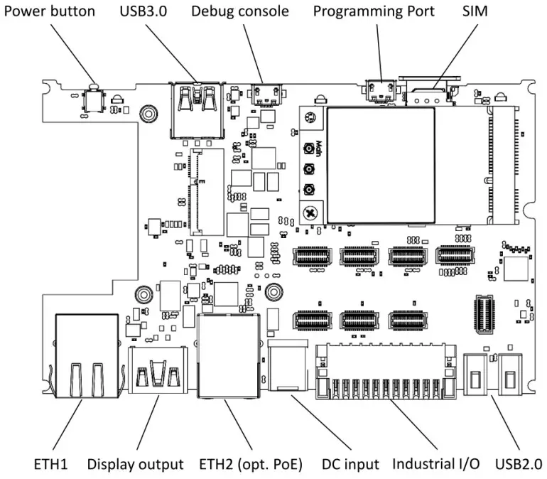
Internal Connectors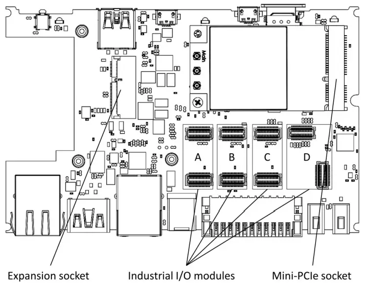
DC Power Jack (J7)
DC power input connector.
Table 10 DC jack connector pin-out
Pin | Signal Name | 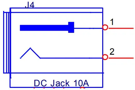 |
1 | DC IN | |
| 2 | GND | |
Table 11 DC jack connector data
Manufacturer | Mfg. P/N |
| Contact Technology | DC-081HS(-2.5) |
The connector is compatible with the SBC-IOT-IMX8PLUS AC PSU and IOTG ACC-CABDC DC cable available from CompuLab.
USB Host Connectors (J8, P17, P18)
SBC-IOT-IMX8PLUS USB3.0 host port is available through standard type-A USB3 connector J8. SBC-IOT-IMX8PLUS USB2.0 host ports are available through two standard type-A USB connectors P17 and P18.
For additional details, please refer to section 3.6 of this document.
Industrial I/O Connector (P8)
SBC-IOT-IMX8PLUS industrial I/O signals are routed to terminal block P8. Pin-out is determined by the I/O modules configuration. For additional details please refer to section 3.12.
Table 12 Industrial I/O add-on connector pin-out
| I/O module | Pin | Singal Name | Isolation Power Domain |
| A | 1 | RS232_TXD / RS485_POS | 1 |
| – | 2 | CAN_L | 1 |
| A | 3 | RS232_RXD / RS485_NEG | 1 |
| – | 4 | CAN_H | 1 |
| A | 5 | ISO_GND_1 | 1 |
| B | 6 | RS232_RXD / RS485_NEG | 2 |
| B | 7 | RS232_TXD / RS485_POS | 2 |
| B | 8 | ISO_GND_2 | 2 |
| D | 9 | IN0 | 3 |
| D | 10 | IN1 | 3 |
| D | 11 | IN2 | 3 |
| C | 12 | RS232_TXD / RS485_POS | 3 |
| D | 13 | IN3 | 3 |
| C | 14 | RS232_RXD / RS485_NEG | 3 |
| D | 15 | OUT0 | 3 |
| D | 16 | OUT1 | 3 |
| D | 17 | OUT3 | 3 |
| D | 18 | OUT2 | 3 |
| D | 19 | 24V_IN | 3 |
| D | 20 | 24V_IN | 3 |
| C/D | 21 | ISO_GND_3 | 3 |
| C/D | 22 | ISO_GND_3 | 3 |
Table 13 Industrial I/O add-on connector data
| Connector type | Pin numbering |
| 22-pin dual-raw plug with push-in spring connections Locking: screw flange Pitch: 2.54 mm Wire cross-section: AWG 20 – AWG 30 Connector P/N: Kunacon HGCH25422500K Mating connector P/N: Kunacon PDFD25422500K NOTE: CompuLab supplies the mating connector with the gateway unit | 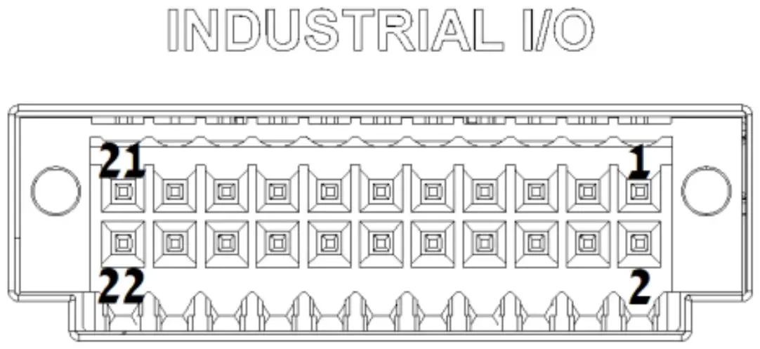 |
Serial Debug Console (P5)
SBC-IOT-IMX8PLUS serial debug console interface is routed to micro USB connector P20. For additional information, please refer to section 3.8 of this documents.
RJ45 Ethernet Connectors (P13, P14)
SBC-IOT-IMX8PLUS Ethernet port ETH1 is routed to RJ45 connector P13. SBC IOT-IMX8PLUS Ethernet port ETH2 is routed to RJ45 connector P14. For additional details, please refer to section 3.5 of this document.
Mini-PCIe socket (P3)
SBC-IOT-IMX8PLUS features one mini-PCIe socket P3 mainly intended for cellular modem modules. P3 implements USB and SIM interfaces. Socket P3 does not implement PCIe signals.
Nano-SIM socket (U10)
The nano-uSIM socket (U10) is connected to mini-PCIe socket P3.
Expansion Connector (P19)
SBC-IOT-IMX8PLUS expansion interafce is available on M.2 Key-E socket with a custom pin-out P19. The expansion connector allows to integrate custom I/O add-on boards into SBC-IOTIMX8PLUS. The following table outlines the connector pin-out and available pin functions.
Table 14 Expansion connector pin-out
| Pin | Singal name | Description | Pin | Signal name | Description |
| 2 | VCC_3.3V | Power output 3.3V | 1 | GND | |
| 4 | VCC_3.3V | Power output 3.3V | 3 | USB_DP | Optional multiplexed USB2 from USB Hub |
| 6 | VCC_5V | Power output 5V | 5 | USB_DN | Optional multiplexed USB2 from USB Hub |
| 8 | VCC_5V | Power output 5V | 7 | GND | |
| 10 | VBATA_IN | Power input (8V – 36V) | 9 | I2C6_SCL | I2C6_SCL / PWM4_OUT / GPIO3_IO19 |
| 12 | VBATA_IN | Power input (8V – 36V) | 11 | I2C6_SDA | I2C6_SDA / PWM3_OUT / GPIO3_IO20 |
| 14 | VBATA_IN | Power input (8V – 36V) | 13 | GND | |
| 16 | EXT_PWRBTNn | ON/OFF input | 15 | ECSPI2_SS0 | ECSPI2_SS0 / GPIO5_IO13 |
| 18 | GND | 17 | ECSPI2_MISO | ECSPI2_MISO / GPIO5_IO12 | |
| 20 | EXT_RESET | Reset input | 19 | GND | |
| 22 | RESERVED | 21 | ECSPI2_SCLK | ECSPI2_SCLK / GPIO5_IO10 | |
| 24 | NC | Key E notch | 23 | ECSPI2_MOSI | ECSPI2_MOSI / GPIO5_IO11 |
| 26 | NC | Key E notch | 25 | NC | Key E notch |
| 28 | NC | Key E notch | 27 | NC | Key E notch |
| 30 | NC | Key E notch | 29 | NC | Key E notch |
| 32 | GND | 31 | NC | Key E notch | |
| 34 | I2C5_SDA | I2C5_SDA / PWM1_OUT / GPIO3_IO25 | 33 | GND | |
| 36 | I2C5_SCL | I2C5_SCL / PWM2_OUT / GPIO3_IO21 | 35 | JTAG_TMS | SoC JTAG |
| 38 | GND | 37 | JTAG_TDI | SoC JTAG | |
| 40 | JTAG_TCK | SoC JTAG | 39 | GND | |
| 42 | GND | 41 | JTAG_MOD | SoC JTAG | |
| 44 | RESERVED | 43 | JTAG_TDO | SoC JTAG | |
| 46 | SD2_DATA2 | SD2_DATA2 / GPIO2_IO17 | 45 | GND | |
| 48 | SD2_CLK | SD2_CLK/ GPIO2_IO13 | 47 | LVDS_CLK_P | LVDS output clock |
| 50 | SD2_DATA3 | SD2_DATA3 / GPIO2_IO18 | 49 | LVDS_CLK_N | LVDS output clock |
| 52 | SD2_CMD | SD2_CMD / GPIO2_IO14 | 51 | GND | |
| 54 | SD2_DATA0 | SD2_DATA0 / GPIO2_IO15 | 53 | LVDS_D3_N | LVDS output data |
| 56 | GND | 55 | LVDS_D3_P | LVDS output data | |
| 58 | SD2_DATA1 | SD2_DATA1 / GPIO2_IO16 | 57 | GND | |
| 60 | SD2_nRST | SD2_nRST / GPIO2_IO19 | 59 | LVDS_D2_N | LVDS output data |
| 62 | GND | 61 | LVDS_D2_P | LVDS output data | |
| 64 | RESERVED | 63 | GND | ||
| 66 | GND | 65 | LVDS_D1_N | LVDS output data | |
| 68 | RESERVED | 67 | LVDS_D1_P | LVDS output data | |
| 70 | RESERVED | 69 | GND | ||
| 72 | VCC_3.3V | Power output 3.3V | 71 | LVDS_D0_P | LVDS output data |
| 74 | VCC_3.3V | Power output 3.3V | 73 | LVDS_D0_N | LVDS output data |
| 75 | GND |
Indicator LEDs
The tables below describe SBC-IOT-IMX8PLUS indicator LEDs.
Table 15 Power LED
| Main power connected | LED state |
| Yes | On |
| No | Off |
General purpose LEDs are controlled by SoC GPIOs.
Table 16 User LED #1
| GP5_IO05 state | LED state |
| Low | Off |
| High | Red |
Table 17 User LED #2
| GP5_IO01 state | GP4_IO28 state | LED state |
| Low | Low | Off |
| Low | High | Green |
| High | Low | Red |
| High | High | Yellow |
Antenna Connectors
SBC-IOT-IMX8PLUS features up-to four connectors for external antennas.
Table 18 Default antenna connector assignment
| Connector Name | Function | Connector Type |
| WLAN-A / BT | WiFi/BT main antenna | RP-SMA |
| WLAN-B | WiFi auxilalry antenna | RP-SMA |
| WWAN | LTE main antenna | SMA |
| AUX | GPS antenna | SMA |
MECHANICAL
Heat Plate and Cooling Solutions
SBC-IOT-IMX8PLUS is provided with an optional heat-plate assembly. The heat-plate is designed to act as a thermal interface and should usually be used in conjunction with a heat-sink or an external cooling solution. A cooling solution must be provided to ensure that under worst-case conditions the temperature on any spot of the heat-spreader surface is maintained according to the SBC-IOTIMX8PLUS temperature specifications. Various thermal management solutions can be used, including active and passive heat dissipation approaches.
Mechanical Drawings
SBC-IOT-IMX8PLUS 3D model is available for download at:
https://www.compulab.com/products/sbcs/sbc-iot-imx8plus-nxp-i-mx8m-plus-internet-of-thingssingle-board-computer/#devres
OPERATIONAL CHARACTERISTICS
Absolute Maximum Ratings
Table 19 Absolute Maximum Ratings
| Parameter | Min | Max | Unit |
| Main power supply voltage | -0.3 | 40 | V |
NOTE: Stress beyond Absolute Maximum Ratings may cause permanent damage to the device.
Recommended Operating Conditions
Table 20 Recommended Operating Conditions
| Parameter | Min | Typ. | Max | Unit |
| Main power supply voltage | 8 | 12 | 36 | V |
Support
© 2022 CompuLab
No warranty of accuracy is given concerning the contents of the information contained in this publication. To the extent permitted by law, no liability (including a liability to any person because of negligence) will be accepted by CompuLab, its subsidiaries or employees for any direct or indirect loss or damage caused by omissions from or inaccuracies in this document.
CompuLab reserves the right to change details in this publication without notice.
Product and company names herein may be the trademarks of their respective owners.
CompuLab
17 Ha Yetzira St., Yokneam Illit 2069208, Israel
Tel: +972 (4) 8290100
www.compulab.com
Fax: +972 (4) 8325251