JET JBOS-5 Benchtop Oscillating Spindle Sander Instruction Manual
Warnings
- Read and understand the entire contents of this manual before attempting assembly or operation. Do not use this tool until proper training and knowledge have been obtained.
- Keep guards in place and in working order.
- Keep fingers and hands away from the spindle while in operation. Avoid getting fingers too close to the drum.
- Remove adjusting keys and wrenches. Form habit of checking to see that keys and adjusting wrenches are removed before operating.
- Keep work area clean. Cluttered areas and benches invite accidents.
- Don’t use in dangerous environment. Don’t use power tools in damp or wet locations, or expose them to rain.
- Keep children and visitors away. All children and visitors should be kept a safe distance from work area.
- Don’t force tool. It will do the job better and be safer at the rate for which it was designed.
- Use right tool. Don’t force a tool or attachment to do a job for which it was not designed.
- Wear proper apparel. No loose clothing, gloves, neckties, rings, bracelets, or other jewelry to get caught in moving parts. Nonslip footwear is recommended. Wear protective hair covering to contain long hair.
- Wear safety glasses (must comply with ANSI Z87.1). Everyday eyeglasses only have impact resistant lenses; they are not safety glasses. Also use face or dust mask if cutting operation is dusty.
- Don’t overreach. Keep proper footing and balance at all times.
- Turn the machine off and unplug from the power source before changing spindles.
- Be sure the spindle drum is in good condition with no tears or holes before operating the sander.
- Disconnect tools before servicing and when changing accessories such as blades, bits, cutters, etc.
- Avoid accidental starting. Make sure switch is in “OFF” position before plugging in power cord.
- Never stand on tool. Serious injury could occur if the tool is tipped or if the cutting tool is accidentally contacted.
- Check damaged parts. Before further use of the tool, a guard or other part that is damaged should be carefully checked to ensure that it will operate properly and perform its intended function – check for alignment of moving parts, binding of moving parts, breakage of parts, mounting, and any other conditions that may affect its operation. A guard or other part that is damaged should be properly repaired or replaced.
- Do not operate tool while under the influence of drugs, alcohol or any medication.
- Shut off power before servicing or adjusting.
- Never leave the tool running while unattended. Turn power off. Don’t leave until the tool comes to a complete stop.
- Do not operate this machine while tired or under the influence of drugs, alcohol or any medication.
WARNING: This product can expose you to chemicals including cadmium which is known to the State of California to cause cancer and birth defects or other reproductive harm. For more information go to http://www.p65warnings.ca.gov.
WARNING: Drilling, sawing, sanding or machining wood products generates wood dust and other substances known to the State of California to cause cancer. Avoid inhaling dust generated from wood products or use a dust mask or other safeguards for personal protection. Wood products emit chemicals known to the State of California to cause birth defects or other reproductive harm. For more information go to http://www.p65warnings.ca.gov/wood.
Introduction
This manual is provided by JET covering the safe operation and maintenance procedures for a JET Model JBOS5 Oscillating Spindle Sander. This manual contains instructions on installation, safety precautions, general operating procedures, maintenance instructions and parts breakdown. This machine has been designed and constructed to provide consistent, long-term operation if used in accordance with instructions set forth in this manual. If there are any questions or comments, please contact either your local supplier or JET. JET can also be reached at our web site: www.jettools.com.
Specifications
- Model Number: JBOS-5
- Stock Number: 708404
- Table Size (in.): 14-1/2 x 14-1/2
- Table Tilt (deg.): 0 to 45 down
- Height, without spindle (in.): 18-3/4
- Base Footprint (in.): 11-3/4 x 11-3/4
- Spindle Speed (RPM): 1,725
- Oscillations per Minute: . 30
- Maximum Length of Oscillation (in.): 1
- Oscillation Gear Environment: sealed oil bath
- Provided sanding sleeves grit: 100
- Dust Port outside diameter (in.): 2
- Power Cord length (ft.): 5-1/2
- Motor (TEFC): TEFC Induction, 1/2 HP, 1PH, 110V, 60Hz, 7.5A
- Switch: manual, with removable safety key
- Net Weight (lb): 77
- Shipping Weight (lb): 82
The above specifications were current at the time this manual was published, but because of our policy of continuous improvement, JET reserves the right to change specifications at any time and without prior notice, without incurring obligations.
Unpacking and Setup
Contents of the Shipping Container

Figure 1 Contents of Shipping Container
- 1 Spindle Sander
- 1 Spindle Storage Plate (pre-installed)
- 1 Insert Storage Plate (pre-installed)
- 2 Round Opening Inserts (3/4” and 2”)
- 2 Oblong Opening Inserts (3/4” and 2”)
- 5 Sanding Spindles & Sleeves (all 100 Grit):
- 1/4”x6”; 1/2”x6”; 5/8”x6”;
- 1-1/2”x5-1/2”; 2”x5-1/2”
- 1 Open End Wrench (10-12mm)
- 2 Open End Wrenches (14-17mm)
- 1 Operator’s Manual
- 1 Warranty Card
Finish removing all contents from the shipping container, and compare items with the list above. Contact your distributor or JET if any parts are missing. Do not discard any shipping material until the sander is set up and running properly.
Report damage, if any, to your local distributor and/or shipping company.
Exposed metal surfaces, including spindles, have been coated with a protectant. Clean these surfaces with a mild solvent or kerosene. Clean the spindles. Do not use lacquer thinner, paint thinner, or gasoline, as these will damage painted surfaces.
Periodically apply paste wax or other protectant to the table top to prevent rusting.
Spindle and Insert Storage Plates
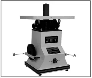
Figure 2
Clean the insert plates and push the unused inserts into Storage Plate B. Place spindles in the opposite Storage Plate A.
Installing Spindles
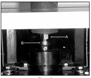
Figure 3
- Before inserting the threaded spindle into the spindle housing, make sure the surfaces are clean.
- Thread the spindle counterclockwise into the spindle housing.
- Using the provided wrenches, tighten the spindle nut (A, Figure 3) counterclockwise while holding the spindle housing flat (B, Figure 3) with the other wrench.
NOTE: Do not overtighten the spindle as it may be difficult to remove after the sanding operation.
Insert Plates
- Always use an insert plate.
- There are 2 oblong, and 2 round insert plate included with the machine. The oblong insert plates are used when the table is tilted for bevel sanding. Each plate has a notch on the outer edge to ensure that it is inserted properly. (See page 9 to determine which insert plate to use with a particular spindle.)
Setup for 90°
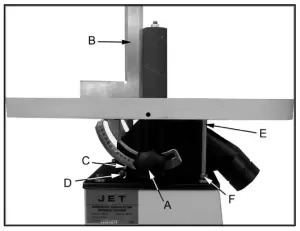
Figure 4
- Loosen both knobs, (A, Figure 4) and place the table in the 0° position.
- Place a square (B, Figure 4) on the table. Rest the long section of the square against the sanding drum. The square should be flat against the table and the sanding drum.
- If the table needs adjustment loosen both knobs and tilt the table so that the square is flat against the table and sanding drum.
- Make sure the pointer (C, Figure 4) reads 0°. If the pointer needs adjusting loosen the screw (D, Figure 4), and adjust to the correct position.
- Loosen lock nut (F, Figure 4), adjust the 90° stop bolt (E, Figure 4) with a 13mm open wrench so that it rests against the bottom side of the table, and re-tighten the lock nut (F, Figure 4) with a 12mm open wrench.
Setup for Bevel Sanding
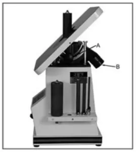
Figure 5
- Loosen both knobs (A, Figure 5) and adjust the table to the desired angle.
- Tighten both knobs.
Dust Collection
The dust port (B, Figure 5) can be hooked directly to a 2” hose for dust collection. See your local JET distributor for the complete line of dust collectors, as well as Hoses and Accessories. Customize your installation and obtain maximum performance with JET dust hoods, hoses, clamps, fittings, and blast gates.
Turning the Sander On & Off
Note: Before hooking the sander to the power source, make sure the switch is in off position. The sander can be turned on by flipping the switch to the on position.
There is a removable key in the tip of the switch that can be removed in the off position. When the key has been removed the dust collector cannot be used.
Removing Spindles
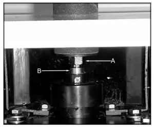
Figure 6
Using the provided wrenches, loosen the spindle nut (A, Figure 6) clockwise while holding the spindle housing flat (B, Figure 6) with the other wrench.
Changing Sanding Sleeves
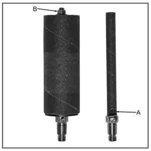
Figure 7
1/4″, 1/2″ and 5/8″
- Loosen the clamp (A, Figure 7) with a cross point screwdriver.
- Remove the sanding sleeve from the spindle shaft.
- Install the new sleeve, making sure to re-tighten the clamp.
1-1/2″ and 2″ (optional 3″)
- Loosen the nut (B, Figure 7) with the provided wrench.
- Remove the sanding sleeve from the spindle shaft.
- Reverse these steps to install the new sanding sleeve.
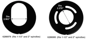
Insert Plate Diameters
This will assist you in determining which spindle diameters will work in each insert plate.

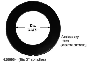
Optional Accessories (purchased separately)
- 709534 …… 3” Dia. Spindle Assembly
- 6286984 …. Table Insert for 3” Spindle
- JW1000 ….. Dust Port Reducer, 4″ to 2-1/4″ O.D. – 2″ I.D.
Sanding Sleeves (4 per pack):
| Stock No. | Diameter (in.) | Length (in.) | Grit |
| 575891 | 1/4 | 6 | 60 |
| 575893 | 1/4 | 6 | 100 |
| 575894 | 1/4 | 6 | 150 |
| 575901 | 1/2 | 6 | 60 |
| 575903 | 1/2 | 6 | 100 |
| 575904 | 1/2 | 6 | 150 |
| 575906 | 5/8 | 6 | 60 |
| 575908 | 5/8 | 6 | 100 |
| 575909 | 5/8 | 6 | 150 |
| 575921 | 1-1/2 | 5-1/2 | 60 |
| 575923 | 1-1/2 | 5-1/2 | 100 |
| 575924 | 1-1/2 | 5-1/2 | 150 |
| 575931 | 2 | 5-1/2 | 60 |
| 575933 | 2 | 5-1/2 | 100 |
| 575934 | 2 | 5-1/2 | 150 |
| 575941 | 3 | 5-1/2 | 60 |
| 575943 | 3 | 5-1/2 | 100 |
| 575944 | 3 | 5-1/2 | 150 |
Replacement Parts
Replacement parts are listed on the following pages. To order parts or reach our service department, call 1-800- 274-6848 Monday through Friday, 8:00 a.m. to 5:00 p.m. CST. Having the Model Number and Serial Number of your machine available when you call will allow us to serve you quickly and accurately.
Non-proprietary parts, such as fasteners, can be found at local hardware stores, or may be ordered from JET. Some parts are shown for reference only, and may not be available individually.
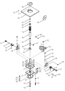
Table Assembly for the JBOS-5
Base and Motor Assembly for the JBOS-5
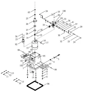
Parts List for the JBOS-5
| Index No | Parts No | Description | Size | Qty |
| 1 | 6286914W | Base | 1 | |
| 2 | 6286891 | Top Plate | 1 | |
| 3 | JBOS5-03 | On/Off Switch | 1 | |
| 4 | 6286915 | Strain Relief Bushing | 1 | |
| 5 | 6286916 | Power Cord | 1 | |
| 6 | 6286485 | Phillips Pan Head Screw | M6x22mm 4 | 4 |
| 7 | 6286918 | Rubber Feet | 4 | |
| 8 | 6286919 | Washer | 1/4″ | 6 |
| 9 | 6286486 | Hex Nut | M6 | 4 |
| 10 | 6286921 | Phillips Pan Head Screw | 3/16″-24×1-3/4″ | 2 |
| 11 | 6286922 | Phillips Pan Head Screw | 3/16″-24×3/4″ | 2 |
| 12 | 6286923 | Gear Washer | 3/16″ | 4 |
| 13 | 6286924 | Hex Nut | 3/16″-24 | 4 |
| 14 | JBOS5-14 | Switch Box | 1 | |
| 15 | 6286912 | Motor | 1/2 HP | 1 |
| 16 | 6286926 | Key | 6x6x50 mm | 1 |
| 17 | 6286927 | Flat Head Screw | M4x10 | 2 |
| 18 | 6286928 | Worm Shaft | 1 | |
| 19 | 6012098 | Set Screw | M5x0.8Px5 | 2 |
| 20 | 6286930 | Transmission Rod | 1 | |
| 21 | 6286931 | Hex Nut | M8 | 2 |
| 22 | 6286932 | Connecting Rod | 2 | |
| 23 | 6286933 | Washer | 1/4° | 4 |
| 24 | 6286488 | Nylon Nut | M5 | 2 |
| 25 | BB-6804 | Ball Bearing | 6804-2RS | 1 |
| 26 | 6286470 | Transmission | 1 | |
| 27 | BB-6006ZZ | Ball Bearing | 6006ZZ | 1 |
| 28 | 6286938 | C-Snap Ring | R60 | 1 |
| 29 | 6286939 | Bushing | 4 |
| 30 | 6286481 | Set Screw | M5X6 | 2 |
| 31 | 6286482 | E-Ring | ETW-4 | 2 |
| 32 | 6286471 | Connecting Shaft | 1 | |
| 33 | 6286472 | Bracket | 1 | |
| 34 | 6286473 | Worm | 1 | |
| 35 | 6286490 | Hex Socket Cap Screw | M6x15 | 4 |
| 36 | 6286476 | Shaft | 1 | |
| 37 | 6286480 | Crank Shaft | 2 | |
| 38 | 6286474 | Spring Washer | 1/4″ | 4 |
| 39 | 6286475 | Key | 4x4x15 mm | 1 |
| 40 | BB-6001ZZ | Ball Bearing | 6001ZZ | 2 |
| 41 | 6286478 | C-Snap Ring | S12 | 2 |
| 42 | 6286479 | C-Snap Ring | R28 | 2 |
| 43 | 6286483 | Spring Washer | 5/16″ | 11 |
| 44 | 6286484 | Flat Washer | 5/16″ | 11 |
| 45 | 6286948 | Housing | 1 | |
| 46 | 6286949 | L-Type Bracket-Right | 2 | |
| 48 | 6286951 | Screw | M8x25 | 11 |
| 49 | JBOS5-49 | Hex Cap Screw | M8x110 | 1 |
| 52 | 6286951 | Screw | M8x16 | 2 |
| 53 | JBOS5-53 | Support Trunnion-Right | 1 | |
| 54 | JBOS5-54 | Support Trunnion-Left | 1 | |
| 55 | JBOS5-55 | JET Lock Knob | M6x15 | 2 |
| 56 | JBOS5-56 | Hex Socket Cap Screw | M5x15 | 6 |
| 57 | 6286492 | Set Screw | M6x5 | 1 |
| 58 | 6286961 | Pointer | 1 |
| 59 | 6286493 | Gear Washer | 1/4″ 1 |
| 60 | 6286963 | Round Cross Head Screw | M5x10 4 |
| 61 | 6286964 | Dust Cover | 1 |
| 62 | 6286894 | Main Spindle serial #2014090 & lower | 1 | |
| 6286894N | Main Spindle serial #2024091 & higher | 1 | ||
| 62-1 | S0520020 | C-Ring | 1 | |
| 63 | 6286967 | Cover | 1 | |
| 65 | JBOS5-65 | C-Snap Ring | S28 | 1 |
| 66 | JBOS5-66 | 5/8″ Sanding Spindle | W-12UNC, LH | 3 |
| JBOS5-71 | 1/2″ Sanding Spindle (not shown) | W-12UNC, LH | 1 | |
| JBOS5-72 | 1/4″ Sanding Spindle (not shown) | W-12UNC, LH | 1 | |
| 67 | JBOS5-67 | Key | 6x6x50 mm | 2 |
| 68 | 6286904 | 2″ P.V.0 Bushing | 1 | |
| 6286903 | 1-1/2″ P.V.0 Bushing (not shown) | 1 | ||
| 70 | JBOS5-70 | Scale Label | 1 | |
| 74 | Sanding Sleeve (see page 10) | |||
| 79 | 6286495 | Spring Pin | 3×12 mm | 1 |
| 80 | 6286796 | 5/8″ Clamp | 1 | |
| 6286795 | 1/2″ Clamp (not shown) | 1 | ||
| 6286794 | 1/4″ Clamp (not shown) | 1 | ||
| 82 | 6286973W | Table | 1 | |
| 83 | 6286798 | 2″ Lower Follower Plate | 2 | |
| 6286974 | 1-1/2- Lower Follower Plate (not shown) | 1 | ||
| 85 | 6286799 | 2″ Upper Follower Plate | 1 | |
| 6286976 | 1-1/2- Upper Follower Plate (not shown) | 1 | ||
| 86 | 6286977 | Washer | 5/16″ | 3 |
| 87 | 6286978 | Hex Nut | 5/16″ | 3 |
| 88 | 6286979 | Oblong Table Insert (for 1-1/2″ and 2″ spindles) | 1 |
| 89 | 6286980 6286981 6286982 | Round Table Insert (for 1-1/2″ and 2″ spindles) Oblong Table Insert (for 1/4″ to 1″ spindles), not shown Round Table Insert (for 1/4″ to 1- spindles),not shown | 1,1,1 |
| 92 | JBOS5-92 | Oil Cap | 1 |
| 93 | JET-55B | JET Logo 5″ x 5″ | 1 |
| 94 | JBOS5-94 | Warning Label | 1 |
| 95 | JBOS5-95 | I.D Label | 1 |
| 96 | JBOS5-96B | Stripe (Black) | 1 |
| 97 | JBOS5-97 | Storage Plate for Drums | 1 |
| 98 | JBOS5-98 | Storage Plate for Table Inserts | 1 |
| 99 | TS-1514011 | Hex Socket Cap Screw M6x12 | 6 |
| 100 | JBOS5-100 | Oil Cover | 1 |
| 101 | JBOS5-101 | Pan Head Screw 3/16″x1/4″ | 2 |
| 102 | JBOS5-102 | Model Label | 1 |
| JBOS5-105 | Open End Wrench (not shown) 14-17mm | 2 | |
| JBOS5-106 | Open End Wrench (not shown) 10-12mm | 1 | |
| 709530 | Hardware Kit (not shown) | ||
| 30203000A | 1/4″ Spindle Assembly (includes #60,66,80) | ||
| 30203000B | 1/2″ Spindle Assembly (includes #60,66,80) | ||
| 302030001 | 5/8″ Spindle Assembly (includes #60,66,80) | ||
| 30203000D | 1-1/2″ Spindle Assembly (includes #66-68 and 85-87) | ||
| 30203000E | 2″ Spindle Assembly (includes #66-68 and 85-87) |
427 New Sanford Road LaVergne, Tennessee 37086
Phone: 800-274-6848
www.jettools.com


