
![]() SXE 425 TurboTec/SXE 450 TurboTec-Random Orbital Sander
SXE 425 TurboTec/SXE 450 TurboTec-Random Orbital Sander
Instruction Manual
![]()
SXE 450 TurboTec | SXE 425 TurboTec | ||
| D | mm (in) | 150 (529/32) | 125 (415/16) |
| P1 | W | 350 | 320 |
| P2 | W | 180 | 160 |
| no | min-1 (rpm) | 4200-9200 | 4200-9200 |
| no, TB | min-1 (rpm) | 11000 | 11000 |
| ni, TB | min-1 (rpm) | 8500 | 9000 |
| so | m1n-1 (opm) | 8400-18400 | 8400-18400 |
| SO, TB | min-1 (opm) | 22000 | 22000 |
| S1, TB | min-1 (opm) | 17000 | 18000 |
| S | mm (in) | 2,8 / 6,2 (1/8/ 1/4) | 5 (3/16) |
| m | kg (lbs) | 2,2 (4.9) | 2,0 (4.4) |
| ah,DS/Kh,DS | m/s2 | 9,0*; 6,0 / 1,5 | 3,5 ; 2,0 / 1,5 |
| ah,p/Khp | m/s2 | 5,0 / 1,5 | 4,5 / 1,5 |
| LpA/KpA | dB(A) | 82 / 3 | 83 / 3 |
| LWA/KWA | dB(A) | 93 / 3 | 94 / 3 |
![]() *2) 2014/30/EU, 2006/42/EC, 2011/65/EU
*2) 2014/30/EU, 2006/42/EC, 2011/65/EU
*3) EN 62841:2015, EN 62841-2-4:2014, EN IEC 63000:2018
2021_03_10, Bernd Fleischmann 
(Vice President Product Engineering & Quality)
*4) Metabowerke GmbH – Metabo-Allee 1 – 72622 Nuertingen, Germany
Conformity Declaration
We declare under our sole responsibility: These random orbital sanders, identified by type and serial number *1), comply with all relevant requirements ofthe directives *2) and standards *3). Technical file at *4) – see page 3.
For the UK only: We as manufacturer and authorized person to compile the technical file, see *4) on page 3, hereby declare under sole responsibility that these random orbital sanders, identified by type and serial number *1) on page 3, fulfill all relevant provisions following UK Regulations S.I. 2016/1091, S.I. 2008/ 1597, S.I. 2012/3032 and Designated Standards EN 62841:2015, EN 62841-2-4:2014, EN IEC 63000:2018.
Specified Use
The random orbital sander is suitable for dry sanding of flat and curved surfaces, wood, plastics, non-ferrous metals, sheet steel, and similar materials, spackled and painted surfaces, and is also suitable for polishing.
The user bears sole responsibility for damage caused by improper use.
Generally accepted accident prevention regulations and the enclosed safety information must be observed.
General Safety Instructions
![]() For your own protection and for the protection of your electrical tool, pay attention to all parts of the text that are marked with this symbol!
For your own protection and for the protection of your electrical tool, pay attention to all parts of the text that are marked with this symbol!![]() WARNING – Reading the operating instructions will reduce the risk of injury.
WARNING – Reading the operating instructions will reduce the risk of injury.![]() WARNING – Read all safety warnings, instructions, illustrations, and specifications provided with this power tool.
WARNING – Read all safety warnings, instructions, illustrations, and specifications provided with this power tool.
Failure to follow all instructions listed below may result in electric shock, fire, and/or serious injury.
Save all warnings and instructions for future reference. Pass on your electrical tool only together with these documents.
Special Safety Instructions
Hold the power tool by insulated gripping surfaces, because the sanding surface may contact its own cord. Cutting a “live” wire may make exposed metal parts of the power tool “live” and could give the operator an electric shock.
Pull the plug out of the socket before making any adjustments, changing tools, carrying out maintenance, or cleaning.
Secure the workpiece against slipping, e.g. with the help of clamping devices.
Wear ear protectors when working for long periods of time. High noise levels over a prolonged period of time may affect your hearing. Hold the machine from the handles provided.
Reducing dust exposure:![]() Some of the dust created using this power tool may contain substances known to cause cancer, allergic reaction, respiratory disease, birth defects, or other reproductive harm. Some examples of these substances are: lead (from lead-based paints), crystalline silica (from bricks cement, etc.), additives for wood treatment (chromate, wood preservative), and some types of wood (like oak and beech dust), metals, asbestos.
Some of the dust created using this power tool may contain substances known to cause cancer, allergic reaction, respiratory disease, birth defects, or other reproductive harm. Some examples of these substances are: lead (from lead-based paints), crystalline silica (from bricks cement, etc.), additives for wood treatment (chromate, wood preservative), and some types of wood (like oak and beech dust), metals, asbestos.
The risk from exposure to such substances will depend on how long the user or nearby persons are being exposed.
Do not let particles enter the body.
To reduce exposure to these substances: work in a well-ventilated area and wear protective equipment, such as dust masks that are specially designed to filter out microscopic particles.
Observe the relevant guidelines for your material, staff, application, and place of application (e.g. occupational health and safety regulations, disposal).
Collect the generated particles at the source, and avoid deposits in the surrounding area.
Use only suitable accessories. In this way, fewer particles enter the environment in an uncontrolled manner.
Use a suitable extraction unit.
Reduce dust exposure with the following measures:
- Do not direct the escaping particles and the exhaust air stream at yourself or nearby persons or on dust deposits.
- Use an extraction unit and/or air purifiers.
- Ensure good ventilation of the workplace and keep it clean using a vacuum cleaner. Sweeping or blowing stirs up dust.
Vacuum or wash protective clothing. Do not blow, beat or brush.
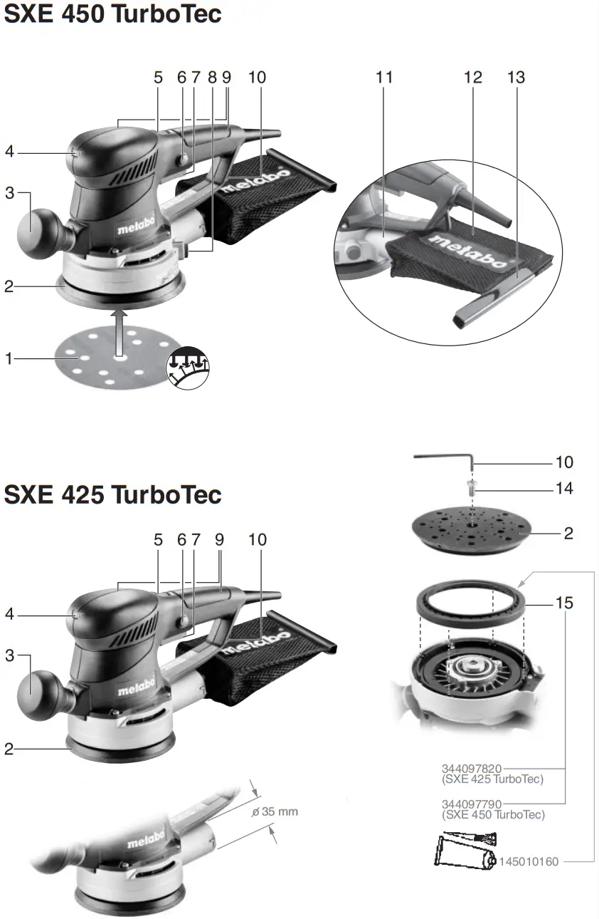
Overview
See page 2.
- Sanding disc
- Support plate
- Additional handles (removable)
- Setting wheel for selecting the oscillating frequency
- TurboBoost switch
- Locking button for continuous activation
- Trigger switch
- Locking button for “Duo” oscillating circuit setting *
- Handle
- Hexagon spanner
- Ejection nozzle
- Dust bag
- Closure band
- Locking screw for the support plate
- Braking ring of support plate brake
Commissioning
![]() Before plugging in, check to see that the rated mains voltage and mains frequency, as stated on the rating label, match your power supply.
Before plugging in, check to see that the rated mains voltage and mains frequency, as stated on the rating label, match your power supply.![]() Always install an RCD with a maximum trip current of 30 mA upstream.
Always install an RCD with a maximum trip current of 30 mA upstream.
Additional handle (removable)
If necessary, you can unscrew the additional handle (3) (right-hand thread).
Installation of the sanding disc
Simple attachment and removal thanks to the Velcro-type fastening.
Simply press on the sanding disc such that the holes in the sanding disc (1) are aligned with the support plate (2).
Use
Duo oscillating circuit setting (only with SXE 450 TurboTec)
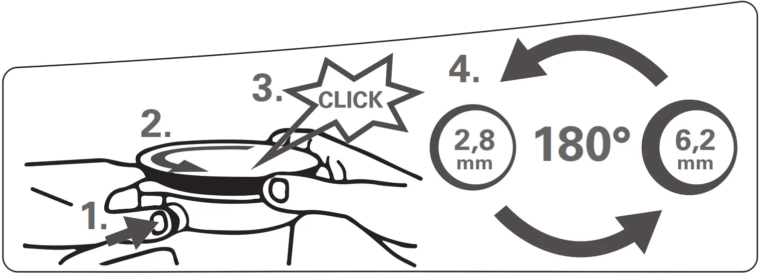
You can choose between two oscillating frequency settings:
- Oscillating circuit high setting (6.2 mm): coarse sanding with high material removal rate
- Oscillating circuit low setting (2.8 mm): fine sanding, polishing
Changing oscillating circuit:
- Disconnect the mains plug!
- Press the locking button (8) and hold it in place.
- Rotate support plate (2) in a counter-clockwise direction until you can hear it engage.
- Continue holding the button.
- Continue turning the support plate half a revolution to the next snap-in point.
- Release the locking button.
On/Off switch, continuous activation
To start the machine, press the trigger switch (7).
For continuous operation, the trigger switch can be locked using the lock button (6). To stop the machine, press the trigger switch (7) again.
Setting oscillating frequency
When the TurboBoost switch (5) is switched off, the oscillating speed can be set at the setting wheel (4). This is also possible during operation.
Recommended oscillating frequency settings:
Plastic materials . . . . . . . . . . . . . . . . . . . . .1-2
Metal, Plexiglas® , old coats of paint . . . . .3-4
Coarse and fine sanding, polishing, wood 5
The best way to determine the ideal setting is through a practical trial.
TurboBoost switch
Actuate the TurboBoost switch (5) during operation to switch on additional power reserves for maximum material removal rate.
Dust extraction
To optimize the dust extraction performance, fit the sanding disc such that the holes on the sanding disc (1) are aligned to the support plate (2).
Note: We recommend connecting a suitable extraction device when sanding abrasive material (e.g. plaster, etc.).
Own extraction units:
Fit dust bag (12) to the ejection nozzle (11). Pull the dust bag (12) backward to remove it.
Empty the dust bag (12) in good time to optimize dust extraction.
Third-party extraction units:
Connect a suitable extraction device to the ejection nozzle (11).
Cleaning, Maintenance
Emptying the dust bag: remove the closure band (13). Empty the dust bag (12), and clean with an extraction device if necessary. Close the dust bag again with the closure band (13).
They clean the machine regularly, frequently, and thoroughly. This includes vacuum cleaning the ventilation louvers on the motor.
Replacing a worn support plate
Note: If abrasive material (e.g. filled or painted surfaces, etc.) is being sanded, the support plate inevitably wears faster.
- Use the hexagon spanner (10) to unscrew the fixing screw (14) on the support plate.
- Remove support plate (2).
- For replacement support plates, refer to the Accessories chapter.
- Mount support plate (2) and rotate until it engages on the carrier disc.
- Insert the locking screw (14) again and tighten.
Replacing a support plate brake / braking ring
If the idle speed of the support plate increases in course of time, the braking ring (15) is worn and must be replaced.
Note: If abrasive material (e.g. filled or painted surfaces, etc.) is being sanded, the braking ring inevitably wears faster.
- Use the hexagon spanner (10) to unscrew the fixing screw (14) on the support plate.
- Remove support plate (2).
- Replace the old braking ring (15) with the new braking ring (see page 2), ensuring that the new braking ring is in the same position as the old braking ring. Ensure that the position of the marking on the braking ring is correct.
- For proper functioning, apply a thin layer of grease (see page 2) on the braking ring at its contact surface to the support plate.
- Mount support plate (2) and rotate until it engages on the carrier disc.
- Insert the locking screw (14) again and tighten.
Tips and Tricks
Do not press the device too firmly against the surface being sanded. This does not improve, but rather impairs, the sanding performance.
Empty the dust bag (12) in good time to optimize dust extraction.
Use a suitable sanding disc to achieve the best possible work results: Removal of old paint layers = P 40
Pre-sanding of wood = P 60, P 80
Finishing of wood = P 100, P 120
Sanding of veneers, sealing primer, filler, paint = P 180, P 240, P 320, P 400
Accessories
Use only genuine Metabo accessories.
Note: Metabo accessories are adapted to suit the machine’s Velcro-type fastening. This increases the service life of the velcro-type fastening.
Use only accessories which fulfill the requirements and specifications listed in these operating instructions.
See www.metabo.com or the catalog for a complete range of accessories.
Repairs
![]() Repairs to electrical tools must be carried out by qualified electricians ONLY!
Repairs to electrical tools must be carried out by qualified electricians ONLY!
A defective mains cable must only be replaced with a special, original mains cable from Metabo, which is available only from the Metabo service.
If the mains connection cable of this machine is damaged, it must be replaced by the manufacturer or an authorized service center to avoid hazards.
If you have Metabo electrical tools that require repairs, please contact your Metabo service center.
For addresses see www.metabo.com.
You can download spare parts lists from www.metabo.com.
Environmental Protection
Observe national regulations on environmentally compatible disposal and on the recycling of disused machines, packaging, and accessories.![]() Only for EU countries: Never dispose of power tools in your household waste! In 10 accordance with European Guideline 2012/19/EU on used electronic and electric
Only for EU countries: Never dispose of power tools in your household waste! In 10 accordance with European Guideline 2012/19/EU on used electronic and electric
equipment and its implementation in national legal systems, used power tools must be collected separately and handed in for environmentally compatible recycling.
Technical Specifications
Explanatory notes on the specifications on page 3.
Changes due to technological progress are reserved.
D = Diameter of the support plate
P1 = Nominal power input
P2 = Power output
no = Idle speed (setting wheel)
no, TB = Idle speed (TurboBoost switch)
n1, TB = Speed at rated load (TurboBoost switch)
so = Oscillating frequency at idle speed (setting wheel)
SO, TB = Oscillating frequency at idle speed- (TurboBoost switch)
S1 TB = Oscillating frequency at rated load – (TurboBoost switch)
S = Oscillating circuit diameter
m = Weight without mains cable
Measured values determined in conformity with EN 62841![]() Machine in protection class II
Machine in protection class II![]() AC Power
AC Power
The technical specifications quoted are subject to tolerances (in compliance with the relevant valid standards).![]() Emission values
Emission values
These values make it possible to assess the emissions from the power tool and to compare different power tools. The actual load may be higher or lower depending on the operating conditions, the condition of the power tool, or the accessories.
Please allow for breaks and periods when the load is lower for assessment purposes. Arrange protective measures for the user e.g. organizational measures based on the adjusted estimates.
Vibration total value (vector sum of three directions) determined in accordance with EN 62841:
ah = Vibration emission value (surface grinding)
Kh = Uncertainty (vibration)
Typical A-effective perceived sound levels:
LPA = Sound-pressure level
LWA = Acoustic power level
KPA, KWA = Uncertainty
The noise level can exceed 80 dB(A) during operation.![]() Wear ear protectors!
Wear ear protectors!
![]() Metabowerke GmbH
Metabowerke GmbH
Metabo-Allee 1
72622 Nuertingen
Germany
www.metabo.com
170 27 4830 – 0321


