
Contents hide
 LAGUNA SS-14 Spindle Sander

ADDITIONAL MARKINGS AND SAFETY INSTRUCITONS
- The following warning or equivalent wording also appears on the Instruction Manual as well as on the tool per UL987. French equivalent of warning markings also appear on tool for Canada.
“WARNING: For Your Own Safety Read Instruction Manual before Operating Sander- Wear eye protection.
- Support work piece with work table.
- Maintain 1.6 mm clearance between table and sanding belt. The word
“WARNING” shall be not less than 2.4 mm high.
- An Instruction Manual warning user against of injury and precautions, grounding instructions, use of extension cords and important safeguards etc., per UL987 is provided with each tool.
- The instruction manual for a scroll saw shall include the marking information as above and explanation of the use and construction of fixtures, including why and when they are needed.
SAFETY RULES
The safety instructions shall be as illustrated below or employ equivalent wording.
- KEEP GUARDS IN PLACE and in working order.
- REMOVE ADJUSTING KEYS AND WRENCHES. Form habit of checking to see that keys and adjusting wrenches are removed from tool before turning it on.
- KEEP WORK AREA CLEAN. Cluttered areas and benches invite accidents.
- DON’T USE IN DANGEROUS ENVIRONMENT. Don’t use power tools in damp or wet locations, or expose them to rain. Keep work area well lighted.
- KEEP CHILDREN AWAY. All visitors should be kept safe distance from work area.
- MAKE WORKSHOP KID PROOF with padlocks, master switches, or by removing starter keys.
- DON’T FORCE TOOL. It will do the job better and safer at the rate for which it was designed.
- USE RIGHT TOOL. Don’t force tool or attachment to do a job for which it was not designed.
- USE PROPER EXTENSION CORD. Make sure your extension cord is in good condition. When using an extension cord, be sure to use one heavy enough to carry the current your product will draw. An undersized cord will cause a drop in line voltage resulting in loss of power and overheating. Table A shows the correct size to use depending on cord length and nameplate ampere rating. If in doubt, use the next heavier gage. The smaller the gage number, the heavier the cord.
- WEAR PROPER APPAREL Do not wear loose clothing, gloves, neckties, rings, bracelets, or other jewelry which may get caught in moving parts. Nonslip footwear is recommended. Wear protective hair covering to contain long hair.
- ALWAYS USE SAFETY GLASSES. Also use face or dust mask if cutting operation is dusty. Everyday eyeglasses only have impact resistant lenses, they are not safety glasses.
- SECURE WORK. Use clamps or a vise to hold work when practical. It’s safer than using your hand and it frees both hands to operate tool.
- DON’T OVERREACH. Keep proper footing and balance at all times.
- MAINTAIN TOOLS WITH CARE. Keep tools sharp and clean for best and safest performance. Follow instructions for lubricating and changing accessories.
- DISCONNECT TOOLS before servicing; when changing accessories, such as blades, bits, cutters, and the like.
- REDUCE THE RISK OF UNINTENTIONAL STATING. Make sure switch is in off position before plugging in.
- USE RECOMMENDED ACCESSORIES. Consult the owner’s manual for recommended accessories. The use of improper accessories may cause risk of injury to persons.
- NEVER STAND ON TOOL Serious injury could occur if the tool is tipped or if the cutting tool is unintentionally contacted.
- CHECK DAMAGED PARTS. Before further use of the too., a guard or other part that is damaged should be carefully checked to determine that it will operate properly and perform its intended function – check for alignment of moving parts, binding of moving parts, breakage of parts, mounting, and any other conditions that may affect its operation. A guard or other part that is damaged should be properly repaired or replaced.
- DIRECTION OF FEED. Feed work into a blade or cutter against the direction of rotation of the blade or cutter only.
- NEVER LEAVE TOOL RUNNING UNATTENDED. TURN POWER OFF. Don’t leave tool until it comes to a complete stop.
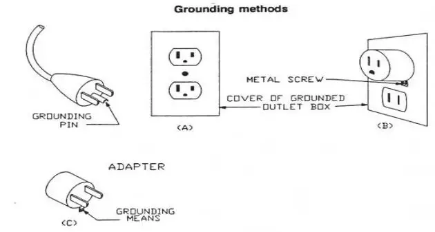
GROUNDING INSTRUCTIONS
- All grounded, cord-connected tools:
In the event of a malfunction or breakdown, grounding provides a path of least resistance for electric current to reduce the risk of electric shock. This tool is equipped with an electric cord having an equipment-grounding conductor and a grounding plug. The plug must be plugged into a matching outlet that is properly installed and grounded in accordance with all local codes and ordinances. Do not modify the plug provided – if it will not fit the outlet, have the proper outlet installed by a qualified electrician. Improper connection of the equipment-grounding conductor can result in a risk of electric shock. The conductor with insulation having an outer surface that is green with or without yellow stripes is the equipment-grounding conductor. If repair or replacement of the electric cord or plug is necessary, do not connect the equipment-grounding conductor to a live terminal. Check with a qualified electrician or service personnel if the grounding instructions are not completely understood, or if in doubt as to whether the tool is properly grounded. Use only 3-wire extension cords that have 3-prong grounding plugs and 3 pole receptacles that accept the tool’s plug. Repair or replace damaged or worn cord immediately. - Grounded, cord-connected tools intended for use on a supply circuit having a nominal rating less than 150 volts:
This tool is intended for use on a circuit that has an outlet that looks like the one illustrated in Sketch A in Fig. 1. The tool has a grounding plug that looks like the plug illustrated in Sketch A in Fig. 1. A temporary adapter, which looks like the adapter illustrated in Sketch B and C, may be used to connect this plug to a 2 pole receptacle as shown in Sketch B if a properly grounded outlet is not available. The temporary adapter should be used only until a properly grounded outlet can be installed by a qualified electrician. This adapter is not permitted in Canada. The green-colored rigid ear, lug, and the like, extending from the adapter must be connected to a permanent ground such as a properly grounded outlet box.
| Table A | ||||||
| Ampere Rating | Volts | Total length of cord in feet | ||||
| 120 | 25 | 50 | 100 | 150 | ||
| 240 | 50 | 100 | 200 | 300 | ||
| More Than | Not More Than | Minimum gage for cord | ||||
| 0 | 6 | 18 | 16 | 16 | 14 | |
| 6 | 10 | 18 | 16 | 14 | 12 | |
| 10 | 12 | 16 | 16 | 14 | 12 | |
| 12 | 16 | 14 | 12 | Not Recommended | ||
SPECIFICATIONS
| MODEL | OVS-TL |
| Table size (L x W) | 370x370mm |
| Table tilt | 0~45° |
| Spindle speed | 1720rpm |
| Oscillations per minute | 29 |
| Oscillation stroke | 24mm |
| Sanding sleeve length | 141mm |
| Max. workpiece height | 80mm |
| Dust port diameter | 50.8mm |
| Motor | 1/2HP /110V |
| Overall (L x W x H ) | 370x370x480mm |
| Net weight | 35kgs |
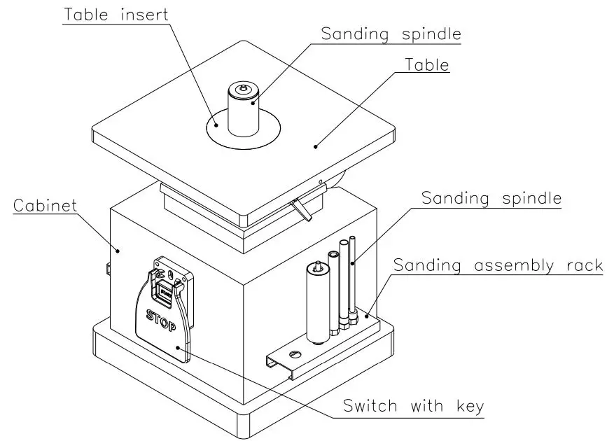
MACHINE LEGEND 
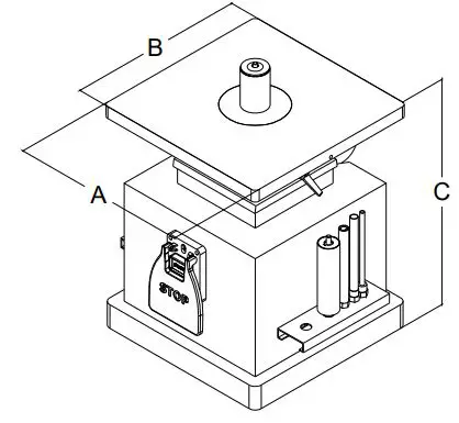
MACHINE DIMENSION 
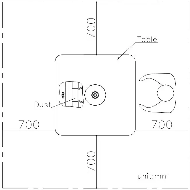
SAFE OPERATING POSITION 
POWER SWITCH ON / OFF
Sanding machine assembly – magnetic switch which to start and stop the machine. The switch locations on the cabinet. When starts the machine the cover needs to be opened and press the button” ON “. If you want to stop the machine, please press the button” OFF”. 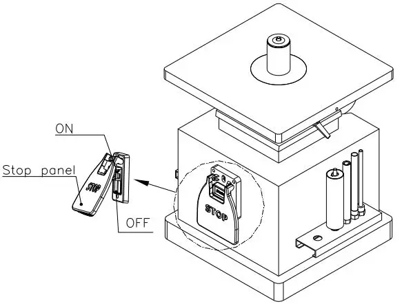
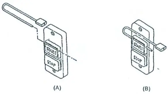
ON/OFF SWITCH PADLOCK
To avoid accidental staring by young children or others not qualified to use the tool, the use of a padlock is required.
To lock out an on/off switch:
- open the padlock. See fig.A
- insert through hole in the star button. See fig.B
- close the padlock.
- Place the key in a safe place out of the reach of children.

INSTRUCTIONS FOR OPERATIONS
- Select spindle that is smaller than the curve to be sanded.
- Use an insert plate that comes closest to the spindle without touching it.
- Make sure that spindle is properly positioned in taper sleeve socket. With the wrench provided , tighten the nut. NOTE: Never over tighten; it may be difficult to remove the spindle later.
- When table is set at a 90° angle, sanding may be done from any corner, or location on table around spindle.
- When table is positioned at any angle other than 90°, it is necessary to position the work piece over the centerline, as shown on table surface.
- Always lock the table with the hand nut when setting at any angle, also to prevent movement lock the tilting gear shaft.
- Always loosen both table lock and tilting gear lock before changing the angle position of the table. Never force the table if it does not tilt easily, reason may be that the locks are still engaged. Never attempt to over ride the stop locks, this will cause damage to the tilting performance.
- A backing board is recommended when sanding thin pieces of metal or any other material. A backing board can be easily constructed by using a piece of wood the length of the table, pushing it into the spindle until a half circle is formed. Clamp each end of the board to the table and proceed to sand the thin material.
- Before leaving the machine remove any particles or pieces left over, make sure the table in 90°.
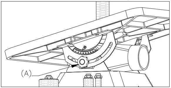
TILTING THE TABLE
- Loosen the two table lock knobs (A), located under the table at both sides of the machine
- Tilt the table forward to the desired angle with your hands.
- An angle scale is provided at the right side of the trunnion to indicate the degree of table tilt.
- Tighten the two table lock knobs securely after the table degree has been adjusted.

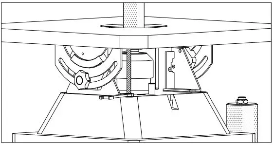
ADJUST THE VERTICALITY BETWEEN THE TABLE AND DRUM
- The verticality between the table and drum has been adjusted by factory before shipment. However, after a long period of operation, the verticality may become inaccurate.
- To adjust the verticality, set the table to a flat horizontal position. The table tilting scale should read zero degrees.
- Place a 90° combinative square on the table and against the drum.
- If the table is not 90° from the drum, adjust the angle of the table by changing the height of the resting post as shown.
- If the table is 90° from the drum, but the scale does not read zero degree, set the scale to read zero degree by loosening the screw on the angle indicator and setting the arrow to zero.

MOUNTING SPINDLE DRUM
- Disconnect the sander from the power source.
- Select the proper diameter of spindle drum.
- Clean the taper part of the spindle drum before mounting it into the spindle.
- Use an open-end wrench to lock the spindle by holding its flat surface. At the same time, use another open-end wrench to tighten the spindle drum.
- Do not over tighten the spindle drum or it will be causing removable problem.
WARNING: Disconnect the power source before removing the drum. 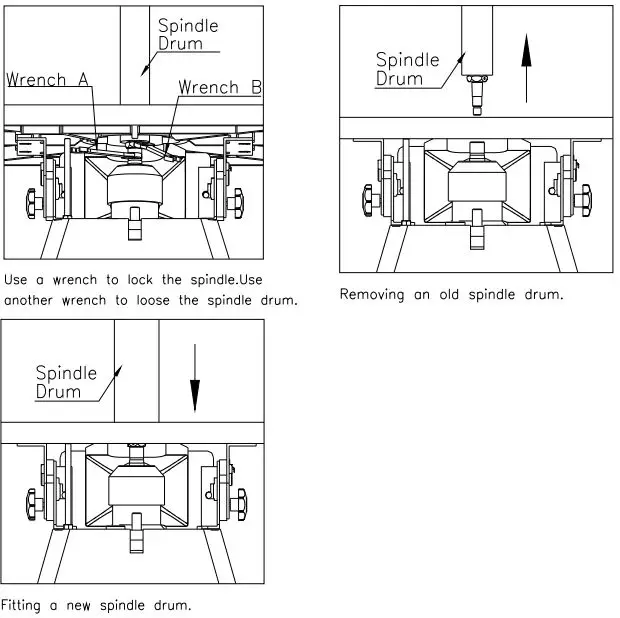
SPARE PARTS FOR OVS-TL
| Key no. | Part no. | DISCRIPTION | Quantity |
| 101 | 30201001L | BASE | 1 |
| 101a | 30201001a | TOP PLATE | 1 |
| 103 | S1006P1 | STRAIN RELIEF | 1 |
| 104 | L000133a | POWER CORD | 1 |
| 105 | S0030622M | PHILIPS HEAD SCREW | 4 |
| 106 | 10107098 | RUBBER FEET | 4 |
| 107 | S0210403 | FLAT WASHER | 6 |
| 108 | S0011600M | HEX. NUT | 4 |
| 109 | S0230300 | SPRING WASHER | 2 |
| 110 | S0030318 | PHILIPS HEAD SCREW | 2 |
| 201 | M329G211 | MOTOR | 1 |
| 202 | S0430650 | KEY | 1 |
| 203 | S0040415M | FLAT HEAD SCREW | 1 |
| 204 | 30202001 | WORM SHAFT | 1 |
| 205 | S0050610M | SET SCREW | 2 |
| 206 | 30202002 | TRANSMISSION ROD | 1 |
| 207 | S0110800M | HEX. NUT | 1 |
| 208 | 30202003 | CONNECTING ROD | 2 |
| 209 | S0210300 | WASHER | 4 |
| 210 | S0120500M | LOCKING NUT | 2 |
| 211 | C1106804K | BEARING | 1 |
| 212 | 30202004 | TRANSMISSION | 1 |
| 213 | C1106006 | BEARING | 1 |
| 214 | S0520059 | C RING | 1 |
| 215 | 30202005 | BUSHING | 4 |
| 216 | S0050506M | SET SCREW | 2 |
| 217 | S05ETW04 | E RING | 2 |
| 218 | 30202020 | CONNECTING SHAFT | 1 |
| 219 | 30202006p | BRACKET | 1 |
| 220 | 30202007p | WORM | 1 |
| 221 | S0010615M | HEX. SOCKET CAP SCREW | 4 |
| 222 | 30202008P | SHAFT | 1 |
| 223 | 30204010 | CRANK SHAFT | 2 |
| 224 | S0230400 | SPRING WASHER | 4 |
| 225 | S0400415 | KEY | 1 |
| 226 | C1106001 | BEARING | 2 |
| 227 | S0521200 | C RING | 2 |
| 228 | S0530028 | C RING | 2 |
| 229 | S0230506 | SPRING WASHER | 11 |
| 230 | S0210500C | FLAT WASHER | 11 |
| 231 | 30202009 | OIL CAP | 1 |
| Key no. | Part no. | DISCRIPTION | Quantity |
| 232 | 30202012 | STORAGE PLATE FOR SPINDLES | 1 |
| 233 | 30202013 | STORAGE PLATE FOR INSERTS | 1 |
| 234 | 30202014 | OIL PLUG | 1 |
| 235 | S0030304 | ROUND HEAD SCREW 3/16″-24UNC*1/4″ | 2 |
| 301 | 30203001 | HOUSING | 1 |
| 304a | 30203003 | BRACKET (RIGHT) | 1 |
| 304b | 30203003a | BRACKET (LEFT) | 1 |
| 305 | S0020825M | HEX. SCREW | 11 |
| 306 | S0020811M | HEX. SCREW | 1 |
| 308 | S0110600 | HEX. NUT | 1 |
| 310a | 40501011 | SUPPORT TRUNNION (RIGHT) | 1 |
| 310b | 40501011a | SUPPORT TRUNNION (LEFT) | 1 |
| 311 | 30204013G | LOCK KNOB | 2 |
| 312 | S0010516M | HEX. SOCKET CAP SCREW | 4 |
| 313 | S0050606M | SET SCREW | 1 |
| 314 | 10102022 | POINTER | 1 |
| 315 | S0220400 | GEAR WASHER | 1 |
| 316 | S0030510M | PHILIPS HEAD SCREW | 1 |
| 317 | 30203005 | DUST COVER | 1 |
| 319 | 30203006 | MAIN SPINDLE | 1 |
| 320 | 30203007 | SWITCH COVER | 1 |
| 322 | S0520028 | C RING | 1 |
| 323 | 30203000H | 3″ SPINDLE ASS’Y (OPTIONAL) | 1 |
| 323a | 30203020 | 3″ SANDING SLEEVE 100 GRIT | 1 |
| 324 | 30203000E | 2″ SPINDLE ASS’Y | 1 |
| 324a | 30203021 | 2″ SANDING SLEEVE 100 GRIT | 1 |
| 325 | 30203000D | 1-1/2″ SPINDLE ASS’Y | 1 |
| 325a | 30203013 | 1-1/2″ SANDING SLEEVE 100 GRIT | 1 |
| 326 | 30203000I | 5/8″ SPINDLE ASS’Y | 1 |
| 326a | 30105076 | 5/8″ SANDING SLEEVE 100 GRIT | 1 |
| 327 | 30203000B | 1/2″ SPINDLE ASS’Y | 1 |
| 327a | 30105079 | 1/2″ SANDING SLEEVE 100 GRIT | 1 |
| 328 | 30203000A | 1/4″ SPINDLE ASS’Y | 1 |
| 328a | 30203022 | 1/4″ SANDING SLEEVE 100 GRIT | 1 |
| 401 | 30204001 | TABLE | 1 |
| 407 | 30204003Q | 2″ TABLE INSERT (OVAL) | 1 |
| 408 | 30204004 | 2″ TABLE INSERT (ROUND) | 1 |
| 409 | 30204005 | 3/4″ TABLE INSERT (ROUND) | 1 |
| 410 | 30204006Q | 3/4″ TABLE INSERT (OVAL) | 1 |
| 411 | 30204007 | 3″ TABLE INSERT (ROUND) (OPTIONAL) | 1 |
| Key no. | Part no. | DISCRIPTION | Quantity |
| 412 | S0310312 | SPRING PIN | 1 |
| 413 | 30201003 | WRENCH | 1 |
| 414 | 10105091 | WRENCH | 1 |
| 416 | J8010004 | WARNING LABEL | 1 |
| 419 | WG000007 | SWITCH COVER | 1 |
| 419a | WG000002 | SWITCH BOX | 1 |
| 419b | WG000003 | SWITCH PIN | 1 |
| 425 | 30202039 | RUBBER PAD | 4 |
| 426 | S0520019 | RING STW-19 | 1 |
| 427 | S0110500L | HEX. NUT 5/16″*18UNC*LH | 1 |
| 1 | 30201001B | STAND | 4 |
| 2 | 30205001G | TOP PLATE (A) | 2 |
| 3 | 30205002G | TOP PLATE (B) | 2 |
| 4 | 30201001D | TIE BAR | 4 |
| 5 | S0060509 | CARRIAGE BOLT | 16 |
| 6 | S0230506 | SPRING WASHER 5/16″ | 16 |
| 7 | S0210500C | WASHER | 16 |
| 8 | S0110500 | NUT 5/16″ | 16 |
| 9 | 10107098 | RUBBER FEET | 4 |
| 10 | S0210403a | WASHER 1/4″ | 4 |
| 11 | S0110600M | NUT 1/4″ | 4 |
| 12 | S0030625M | RD. CROSS SCREW M6xP1.0x25L | 4 |


