 LAGUNA DDB12 Drum Sander

GENERAL SAFETY RULES FOR WOODWORKING MACHINERY
WARNING: Do not attempt to operate the machine until you have read thoroughly and have understood completely all instructions, rules and condition contained in this manual. Failure to comply can result in accidents involving fire, electric shock, or serious personal injury. Keep this owner’s manual and refer to it frequently for continued safe operation.
- 1. Know your machine. For your own safety, read the owner’s manual carefully. Learn its application and limitations, as well as specific potential hazards pertinent to this machine.
2. Make sure all tools are properly grounded. If the tool electrical plug has three prongs, it should be used in a three hole electrical socket. If a three prong or two prong adapters is used, the adapter plug must be properly grounded. Do not remove or disable the third prong.
3. Keep guards in place and in good working order. If a guard must be removed for maintenance or cleaning, make sure it is properly reattached before using the machine again.
4. Remove adjusting keys and wrenches. Form a habit of checking to see that the keys and adjusting wrenches are removed from the machine before turning it on.
5. Keep your work area clean. Cluttered areas and workbenches increase the chance of an accident.
6. Do not use in dangerous environments. Do not use power tools in damp or wet locations or expose them to rain. Keep work areas well illuminated.
7. Keep children away. All visitors should be kept a safe distance from the work area.
8. Make the workshop childproof. Use padlocks, master switches and remove starter keys.
9. Do not force the machine. It will do the job better and be safer at the operating rate for which it is designed.
10. Use the right tools. Do not force the machine or attachments to do a job for which they are not designed. Contact the manufacturer or distributor if there is any question about the machine’s suitability for a particular job. - j 1. Wear proper apparel. Avoid loose clothing, gloves, neckties, bracelets, and jewelry, which could get caught in moving parts. Non-slip footwear is recommended. Wear protective hair covering to contain long hair.
- 12. Always use safety glasses. Also, wear a face or dust mask if the operation area is dusty. Everyday eyeglasses only have impact resistant lenses. They are not safety glasses.
13. Do not over-reach. Keep proper footing and balance at all times.
14. Maintain machine in top condition. Keep machine clean for safety and best performance. Follow instructions for lubrication and changing accessories.
15. Disconnect the machine from the power source before servicing, when changing accessories and when mounting or remounting motor.
16. To avoid accidental starting, make sure the switch is in the OFF position before plugging in the power cord.
17. Never leave the machine running unattended. Turn the power off. Do not leave the machine until it comes to a complete stop.
18. Do not use any power tools while under the effects of drugs, alcohol or any medication.
19. Always wear a face or dust mask if operation creates a lot of sawdust and/or chips. Always operate the tools in a well-ventilated area and provide for proper dust removal. Use a dust-collection system whenever possible.
20. SECURE WORK. Use clamps or a vise to hold work when practical. It’s safer than using your hand and it frees both hands to operate tool.
21. MAINTAIN TOOLS WITH CARE. Keep tools sharp and clean for best and safest performance. Follow instructions for lubricating and changing accessories.
22. USE RECOMMENDED ACCESSORIES. Consult the owner’s manual for recommended accessories. The use of improper accessories may cause risk of injury to persons.
23. NEVER STAND ON TOOL. Serious injury could occur if the tool is tipped or if the cutting tool is unintentionally contacted.
24. CHECK DAMAGED PARTS. Before further use of the tool, a guard or other part that is damaged should be carefully checked to determine that it will operate properly and perform its intended function-check for alignment of moving parts, binding of moving parts, breakage of parts, mounting, and any other conditions that may affect its operation. A guard or other part that is damaged should be properly repaired or replaced. - 25. USE A PROPER EXTENSION CORD. Make sure your extension cord is in good condition. When using an extension cord, be sure to use one heavy enough to carry the current your product will draw. An undersized cord will cause a drop in line voltage resulting in loss of power and overheating. Table 1 shows the correct size to use depending on cord length and nameplate ampere rating. If in doubt, use the next heavier gage. The smaller the gage number, the heavier the cord.
Table
Minimum gage for cord1
| Ampere Rating | 120V
240V | 25ft.
50 It. | 50 It.
100 ft, | 100 It.
200 It. | 150 ft.
300 It. | |
| Not More Mora | ||||||
| Than | Than | AWG | ||||
| 0 | 6 | 18 | 16 | 16 | 14 | |
| 6 | 10 | 18 | 16 | 14 | 12 | |
| 10 | 12 | 16 | 16 | 14 | 12 | |
| 12 | 16 | . 14 | 12 | Not | Recommended | |
JGROUNDlNG INSTRUCTION
In the event of a malfunction or breakdown, grounding provides a path of least resistance for electric current to reduce the risk of electric shock. This tool is equipped with an electric cord having an equipment-grounding conductor and a grounding plug. The plug must be plugged into a matching outlet that is properly installed and grounded in accordance with all local codes and ordinances.
Do not modify the plug provided – if it will not fit the outlet, have the proper outlet installed by a qualified electrician.
Improper connection of the equipment-grounding conductor can result in a risk of electric shock. The conductor with insulation having an outer surface that is green with or without yellow stripes is the equipment-grounding conductor. If repair or replacement of the electric cord or plug is necessary, do not connect the equipment-grounding conductor to a live terminal.
Check with a qualified electrician or service personnel if the grounding instructions are not completely understood, or if in doubt as to whether the tool is properly grounded.
use only 3-wire extension cords that have 3-prong grounding plugs and 3-pole receptacles that accept the tool’s plug.
Repair or replace damaged or worn cord immediately.
This tool is intended for use on a circuit that has an outlet that looks like the one illustrated in Sketch A. The tool has a grounding plug that looks like the plug illustrated in Sketch A. A temporary adapter, which looks like the adapter illustrated in Sketches B and C, may be used to connect this plug to a 2-pole receptacle as shown in Sketch B if a properly grounded outlet is not available. The temporary adapter should be used only until a properly grounded outlet can be installed by a qualified electrician.(This adapter is not permitted in Canada) The green-colored rigid ear, lug, and the like, extending from the adapter must be connected to a permanent ground such as a properly grounded outlet box.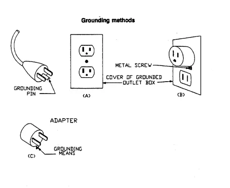
ADDITIONAL SAFiTY RULES FOR VERTICAL SPINDLE SaNIJEr
- 1. WARNING: FOR YOUR OWN SAFETY READ INSTRUCTION MANUAL
BEFORE OPERATING SANDER. WEAR EYE PROTECTION.
2. SUPPORT WORK PIECE WITH MITER GAGE, BCAKSTOP, OR WORKTABLE. MAINTAIN 1/16 INCH MAXIMUM CLEARANCE BETWEEN TABLE AND
SANDING BELT OR DISC,.
3. AVOID KICKBACK BY SANDING IN AVVORDANCE WITH THE DIRECTIONAL ARROWS.
IUNPACKlNGANO CLEANING THE MACHINE!
- 1. The machine is shipped in one carton.
2. Unpack the machine carefully.
3. Ensure that loose parts are present as listed in the manual. If any items are missing or damaged, please contact your local dealer immediately.
4. Remove the rust preventative oil thoroughly. Use a soft cloth moistened with kerosene to remove the oil.
WARNING: Do not use gasoline or lacquer thinner to remove the rust preventative oil, as these can damage the painted surface
MACHINE FEATURED
- The oscillating sanding provides an extremely fine sanding finish.
2. Easily interchangeable spindle. - Two tables are both Rota table.
4. Standard accessories can be stored at the side of the machine.
5. Air ventilation in rear of machine.
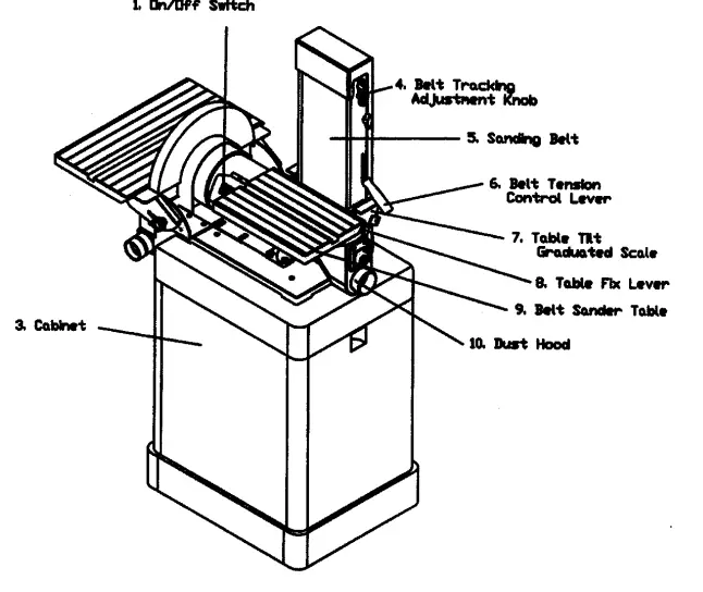
MACHINE LEGEND
 SPECIFICATION

 SPECIFICATION
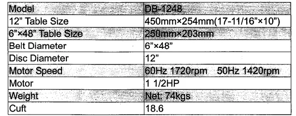
CONNECTING DUST cOLLECTION SYSTEM
There is dust hoods provided for the spindle drum sander and the belt sander, that which should be connected to a dust collector. The dust hoods are located under the tables. Dust hood outlets are 2″ diameter. Use a 2″ diameter air hose to connect both dust hoods to a dust collector.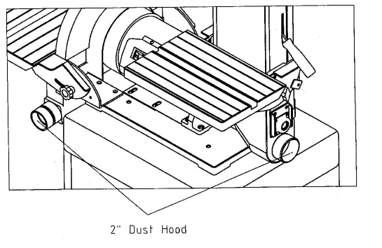
POWER SWITCH ON/OFF
The sander is equipped with a rocker-type power switch to start and stop the sander running. It is located on the junction box of the motor. The Switch has a removable locking key to prevent unauthorized operations. I the sander is not in use for a long time, remove the locking key by pulling it out. It should then be stored in a safe place. To start the sander running, insert the locking key and shift the switch to the left. To stop the sander, shift the switch to the right as shown below.
WARNING: Make sure the power switch is in the OFF position before connecting the sander to the power source.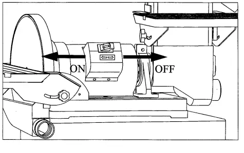
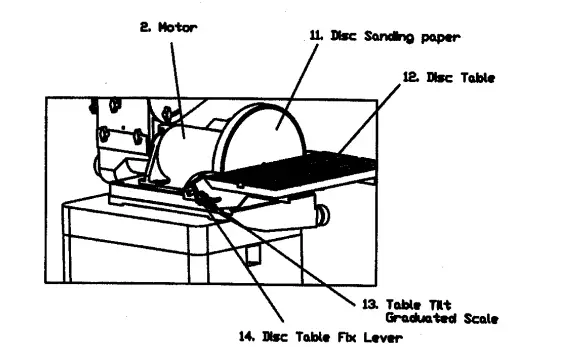
TILTING THE DRUMSANDER TABLE
The drum sander table can be tilted front downward from 0° to 45°Loosen the two table fix levers located under the right and left sides of the table before tilting the table. Tighten both fix levers securely after the table has been tilted. A graduated scale is attached for indicating the tilting degree of the table.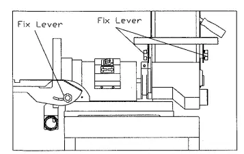
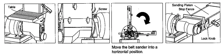
SETTING THE BELT SANDERINAHORIZONTAL POSITION
- Loosen the screw that tightens the motor shaft bracket using a 6 mm. hexagonal wrench.
- Remove the belt sander table.
- Manually move the belt sander into a horizontal position.
- Tighten the screw securely after the belt sander has been positioned horizontally.
- Always remember to mount the stop fence when performing flat surface sanding.

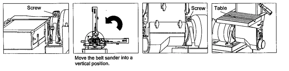
SETTING THE BELT SANDER IN A VERTICAL POSITION
- Loosen the screw that tightens the motor shaft bracket using a 6 mm. hexagonal wrench.
- Manually, move the belt sander into a vertical position.
- Tighten the screw securely after the belt sander has been positioned vertically.
- Mount the table.

REMOVING THE SANDING BELT
- Disconnect the sander from the power source.
- Loosen the 5 lock knobs that tighten the belt guard and then remove it
- Remove the belt sander table. L0osen the 2 lock screws located under the table before removing It.
- Loosen and remove the table tit graduated scale using a 5 mm. hexagonal wrench.
- Loosen the belt tension by shifting the belt tension control lever upward.
- The old sanding belt may now be removed from the right side ock Knd Belt pension

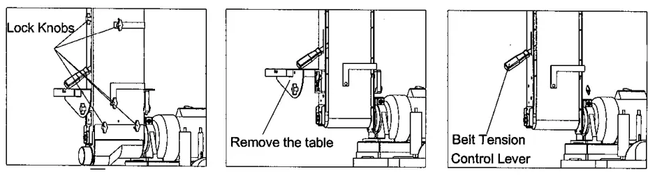
Remove the table MOUNTINGANEW SANDING BELT
- Disconnect the sander from the power source.
- After the old belt has been removed, it is possible to fit a new one.
- Fit a new sanding belt in the same place. Make sure the arrowheads marked on the back of the sanding belt point to the direction indicator attached on the belt guard.
- The new sanding belt should be located in the center position of both rollers.
- Tighten belt tension by shifting the belt tension control lever downwards.
- After the new belt has been mounted, reverse the above procedure to retun the sander to fts original condition.
- It is necessary to make belt tracking adjustments. For details, refer to
- Belt Tracking Adjustment’ on page 13 of this manual.
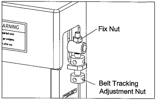
BELT TRACKING ADJUSTMENT
- Disconnect the sander from the power source.
- Manually rotate the sanding belt. At this time, check to see if the sanding belt runs in the center position of the rollers.
- If the sanding belt runs out of proper tracking, make adjustments by turning the belt tracking adjustment knob using the supplied screwdriver.
- Turn the knob in a counter-clockwise direction to move the belt forward. Turn it in a clockwise direction to move the belt backward.
- Loosen the fix nut before turning the belt tension adjustment knob. Tighten the nut securely after the belt tracking has been adjusted.

STOP FENCE
When the sanding platen is set for horizontal sanding, the stop fence should be used to prevent workpieces fiying out during sanding. Mount the stop fence by fastening the two lock knobs on the edge of the sanding platen.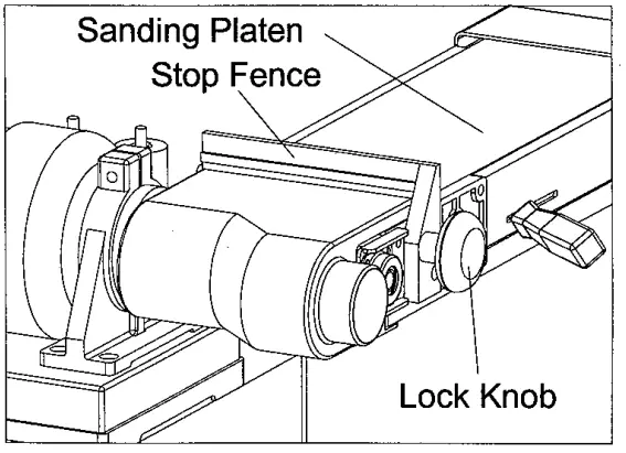
ATTACHING DISC SANDING PAPER
Dismantle the disc table. Remove the old sanding paper from the disc. The disc features a self-adhesive function, so that the sanding paper can easily be attached to the disc.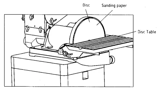
MAINTENANCE
- every day, after work is done, remove dust from the machine and clean it.
- Everyday, after work is done, turn off the power switch and remove the Switch key.
- A build-up of dust in the motor can cause motor damage. Periodic cleaning of the motor is not only recommended, but also mandatory for normal sander performance.
- Keep the machine and attachments clean.
- Protect the spindle sleeves from nicks Clean tanered sleeves and tapered socket before use.
- Check for spindle straightness.
- All bearings are permanently lubricated and require no further lubrication.
WARNING: Always disconnect the sander from the power source before commencing any maintenance.
TROUBLESHOOTING
| TROUBLE | CAUSES | CORRECTION |
| Motor does not run when l?.Ower switch is turned ON”. | 1. Switch is burned out.
2. Connection wire is loose or damaged. | 1. Replace the switch.
2. Tighten or replace the wire. |
| Motor does not run at full speed. | 1. Power voltage is too low.
2. Motor is damaged. | 1. Test voltage.
2. Check and repair motor. |
| Motor does not reach full power. | 1. Incorrect power wiring.
2. Overload. | 1. Replace with the cq rect size power wmng.
2. Reduce sanding load. |
| Motor overheating | 1. Motor is dirty.
2. Motor is damaged. | 1. Clean motor.
2. Check and repair a motor. |
| Excessive machine vibration | Machine is incorrectly leveled. | Adjust machine leveling |
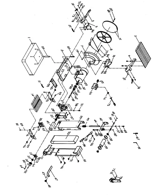
PARTS LIST
| No. | COM No. | DESCRIPTION | QTY. |
| 1 | 30500001 | BASE LOW | 1 |
| 2 | 30500002 | BASE UP | 1 |
| 3 | 21100028 | 12″TABLE WORKING TABLE | 1 |
| 4 | 30300014 | FRONT GRADUATED SCALE | 1 |
| 5 | 30300015 | REAR GRADUATED SCALE | 1 |
| 6 | 30300016 | 12″ DUST HOOD | 1 |
| 7 | 30300017 | DISC GUARD | 1 |
| 8 | 30300018 | DISC | 1 |
| 9 | 30300019 | FRONT BRACKET | 1 |
| 10 | 30300020 | REAR BARACKET | 1 |
| 11 | J3020005 | GRADUATED SCALE | 1 |
| 12 | 30300030 | (6×48″)INDICATOR | 1 |
| 13 | 30400007 | BEARING FIX PLATE | 1 |
| 14 | 21000006A | 6×48″TABLE | 1 |
| 15 | 30400002 | AUXICIARY LEFT SCALE PLATE | 1 |
| 16 | 30400003 | AUXICIARY RIGHT SCALE PLATE | 1 |
| 17 | 30400006 | 6×48″ DUST HOOD | 1 |
| 18 | 30400008 | SHORT SPACER | 1 |
| 19 | 30400009 | LONG SPACER | 1 |
| 20 | 30400004 | RIGHT GRADUATEDSCALE BASE | 1 |
| 21 | J30300027 | GRADUATED SCALE | 1 |
| 22 | S0010615L | CPA M6X15L LEFT SCREW | 1 |
| 23 | M3050000 | MOTOR | 1 |
| 24 | 30500003 | SWITCH BOX | 1 |
| 25 | W0000000 | SWITCH | 1 |
| 26 | S0020529 | SCREW 5/16″X11/2″L | 1 |
| 27 | 30400001 | TILTING FIX BRACKET | 1 |
| 28 | 30400010 | CONNECTION BLOCK | 1 |
| 29 | 30400011 | SANDING PLATEN | 1 |
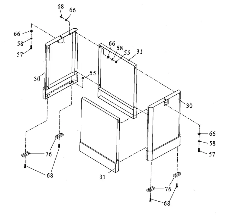
| 30 | 30300036 | RIGHT & LEFT BRACKET | 2 |
| 31 | 30300037 | FRONT-& REAR SPACING PLATE | 2 |
| 32 | S0050404 | 1/4″-24 LINC x1/4″ SOC-SET SCREW | 1 |
| No. | COM No. | DESCRIPTION | QTY. |
| 33 | C1106202 | BEARING 6202 | 1 |
| 34 | 20900049 | BEARING CAP 6202 | 1 |
| 35 | 20101031 | BELT CHANGEHANDLE | 1 |
| 36 | 20101032a | HANDLE KNOB | 1 |
| 37 | S0210501 | FLAT WASHER5/16″ | 2 |
| 38 | C1106201 | BEARING 6201 | 2 |
| 39 | 21100012 | DRIVEN ROLLER | 1 |
| 40 | S0120200 | NYLON NUT 1/4″ | 1 |
| 41 | S0521200 “C” CIRCLIP STW-12 | 1 | |
| 42 | 21100009 | DRIVEN ROLLER BRACKET | 1 |
| 43 | S0310420 | SPRING PIN 4 x 16 | 1 |
| 44 | 21100010 | BRACKET SHAFT | 1 |
| 45 | 21100013 | DRIVE ROLLER | 1 |
| 46 | 21100019 | SCREW | 5 |
| 47 | 20101040 | STOP FENCE | 1 |
| 48 | 20101024 | SCREW | 1 |
| 49 | 21100018 | SPRING | 1 |
| 50 | 21100014A | DUST GUARD A | 1 |
| 51 | 21100014 | DUST GUARD BASE | 1 |
| 52 | S0030304 | ROUND CROSS HEAD SCREW 3/16″ x1/4″ | 4 |
| 53 | 21100029 | SANDING BELT 6×48″ | 1 |
| 54 | S0020300a | FLAT WASHER 5X12 | 4 |
| 55 | S0110400 | 1/4″ -20 UNC NUT | 1 |
| 56 | 21100011 | DRIVEN ROLLER AXLE | 1 |
| 57 | S0010501 | CAP SCREW 5/16″-18UNC x 1″ | 7 |
| 58 | S0230503 | SPING WASHER 5/16″ | 21 |
| 59 | 30400017 | LONG SPACED RING | 4 |
| 60 | 30400015 | COUPLER | 2 |
| 61 | 30102007 | COMPOUND BLOCK | 1 |
| 62 | S0400530 | KEY 5 x 5 x 30 | 1 |
| 63 | 40101011 | UP SPACED RING | 4 |
| 64 | S0010409 | HEXAGONAL SOCKET HEAD SCREW1/4″ x 1/2″ | 7 |
| No. | COM No. | DESCRIPTION | QTY. |
| 65 | 30400016 | PLATE | 1 |
| 66 | S0210500 | FLAT WASHER | 38 |
| 67 | 20103044 | SCREWDRIVER | 1 |
| 68 | S0010501 | HEX SCREW 5/16″-18UNC x 1″ | 20 |
| 69 | S0010500 | CAP 5/16″-18UNC-1/2″ | 2 |
| 70 | 30300038 | FASFEN | 1 |
| 71 | 30300039 | SANDING PAPER | 1 |
| 72 | S0230400 | SPRING WASHER 1/4″ | 8 |
| 73 | S0030308 | PAN-KEAP SCREW 3/16″-24UNC x 5/8″ | 2 |
| 74 | S1006P1 | STRAIN RELIEF BUSHING | 1 |
| 75 | L0000000 | POWER CORD | 1 |
| 76 | 10401029 | PAD | 4 |
| 77 | S0090512 | SCREW 1/4″-20UNC x 1″ | 4 |
| 78 | S0220300 | GEAR WASHER 1/4″ | 2 |
| 79 | S0120500a | LOCKING NUT 5/16″-18UNC | 5 |
| 80 | S0210403 | 1/4″X16 | 8 |
| 81 | S0030308 | PAN-KEAP SCREW 3/16″-24UNC x 1/2″ | 6 |
| 82 | S0110300 | NYLON NUT 3/16″ | 2 |
| 83 | S0020531 | HEX SCREW 5/16″-18UNC x 3″ | 4 |
| 84 | S0120500a | NUT 5/16″ CHEMICAL BLOCK | 2 |
| 85 | 21000007 | MICRO METRIC ADJUSTMENT SCREW | 1 |
| 86 | 201030298 | STEEL BALL | 1 |
| 87 | 20103029A | MICRO METRIC NUT | 1 |
| 88 | F3050001 | CARTON | 1 |
| 89 | A3050001 | POLYLON | 1 |
| 90 | 30400014 | COUPLED AXLE | 1 |
| 91 | S0910104 | HEX WRENCH 6mm | 1 |
| 92 | S0520032 | RTW-32 C” CIRCLIP | 2 |
| 93 | S0520015 | STW-15 C” CIRCLIP | 3 |
| 94 | 13050000 | MANUAL | 1 |