![]()
![]() Wireless Sounder
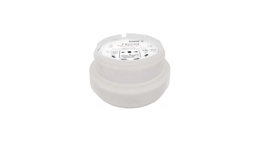
Wireless Sounder
Installation Guide
| Part no | Product Description |
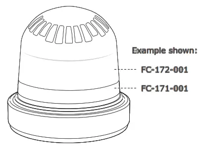
| FC-171-001 | White Wireless Sounder Base Only |
| FC-171-002 | Red Wireless Sounder Base Only |
| FC-172-001 | White Sounder Only |
| FC-172-002 | Red Sounder Only |
| FC-173-002 | Red Sounder Visual Indicator Only |
| FC-173-003 | Amber Sounder Visual Indicator Only |
| FC-173-004 | Clear Sounder Visual Indicator Only |
| FC-178-002 | Red Visual Indicator Only |
| FC-178-003 | Amber Visual Indicator Only |
| FC-178-004 | Clear Visual Indicator Only |
See the Specification section for compliance information.
Pre-installation
![]() Installation must conform to applicable local installation codes and should only be installed by a fully trained competent person.
Installation must conform to applicable local installation codes and should only be installed by a fully trained competent person.
- Ensure that the device is installed as per the site survey.
- The use of a non-metallic spacer should be considered if mounting the device on to a metal surface.
- Do NOT Press the Log On button on a pre-programmed device, as this will cause communication with the Control Panel to be lost. Should this happen, delete the device from the system and add it back on.
- This device contains electronics that may be susceptible to damage from Electrostatic Discharge (ESD). Take appropriate precautions when handling electronic boards.
Components
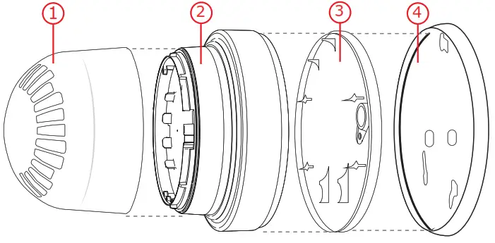
- Sounder/visual indicator variant
- Wireless module
- Battery retaining plate
- Mounting plate
Fix mounting plate
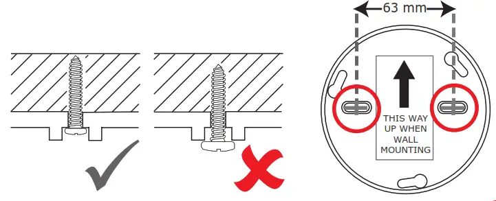
Remove the mounting plate by turning the device ANTICLOCKWISE, to release it from the mounting plate. When wall mounting, ensure the mounting plate is fitted in the orientation shown.
- Use both mounting holes.
- Use suitable fasteners and fixings.
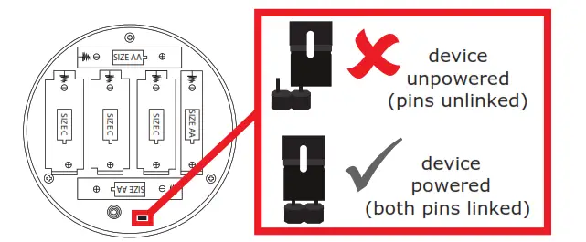
Power device
- Unclip the battery retaining plate from the wireless module.
- When fitting / replacing batteries; observe correct polarity,
- using only specified batteries.
- Connect the power jumper across the PIN header.

- Once powered, reassemble the device.
Optional device locking
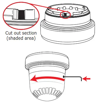
- To unlock the device, insert a 1.5 mm Allen key to depress the locking clip and turn anticlockwise to release.
- To lock the sounder into the wireless module, remove the cutout section as shown.
Configuration
The device’s loop address is configured within the user interface’s menu structure.
- Refer to the programming manual for full programming details.

FireCell = MK98
Fusion = TSD062
WSM = TSD143
Free to download from: www.emsgroup.co.uk
Configuration continued
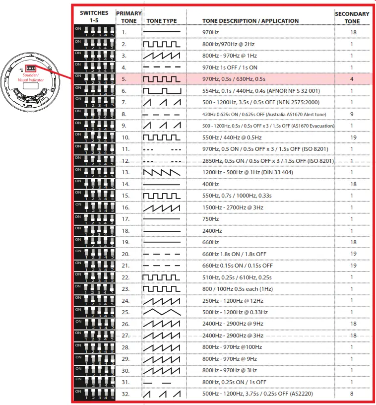
Sounder tone (set on sounder/visual indicator).
The 5-way switch is used to configure the sounder tone.
Default setting: primary tone 5
Volume (set on sounder/visual indicator) The sound output of the unit can also be reduced by adjusting the potentiometer as shown.
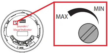 Default setting: high volume
Audio monitoring (Set on wireless module)
The primary and secondary stage sounder tones can be monitored. If enabled and no audio is detected within 10 seconds upon sounder activation, a fault is indicated at the control panel.

Default setting: audio monitoring disabled
Specification
| Operating temperature | -10 to +55 °C |
| Storage temperature | 5 to 30 °C |
| Humidity | 0 to 95% non-condensing |
| Supply | 3x AA Alkaline (Panasonic LR6AD Powerline / Varta 4006 Industrial) 3x C Alkaline (Panasonic R14AD Powerline / Varta 4014 Industrial) |
| CAUTION! Fitting of an incorrect battery type invalidates the product certification and may result in poor performance. | |
| Sounder output | 99 dBA at 1 m (as dispatched) |
| IP rating | IP54 |
| Operating frequency | 868 MHz |
| Output transmitter power | Auto-adjusting 0 to 14 dBm (0 to 25 mW) |
| Dimensions (Ø x D) | 120 mm x 125 mm |
| Weight | 0.65 |
| Location | Type A: For indoor use |
Regulatory Information
| Manufacturer | Carrier Manufacturing Polska Sp. Z o.o. Ul. Kolejowa 24. 39-100 Ropczyce, Poland |
| Year of manufacture | See device serial number label |
| Certification | |
| Certification body | 0905 |
| CPR DoP | See part listing for associated products: [1]0359-CPR-0022, [2]0359-CPR-0040 |
| Approved to | See part listing for associated products: EN54-3:2001. Incorporating Amendments Nos. 1 and 2. Fire detection and fire alarm systems. Part 3: Fire alarm devices – founders.[1] EN54-25:2008. Incorporating corrigenda September 2010 and March 012. Fire detection and fire alarm systems. Part 25: Components using radio links. |
| European Union directives | EMS declares that this device is in compliance with Directive 2014/53/EU. The full text of the EU declaration of conformity is available at the following internet address: www.emsgroup.co.uk |
| 2012/19/EU (WEEE directive): Products marked with this symbol cannot be disposed of f as unsorted municipal waste in the European Union. For proper recycling, return this product to your local supplier upon the purchase of equivalent new equipment, or dispose of it at designated collection oints. For more information see www.recyclethis.info |
![]()


