![]() Bicycles Cadex Tri Frameset Bike
Bicycles Cadex Tri Frameset Bike
User Manual
FRAME SIZING
SIZING GUIDE AND GEOMETRY
Sizing to be used as a reference only. Please check with a local authorized dealer to determine the correct size.
Available sizes may vary from country to country. 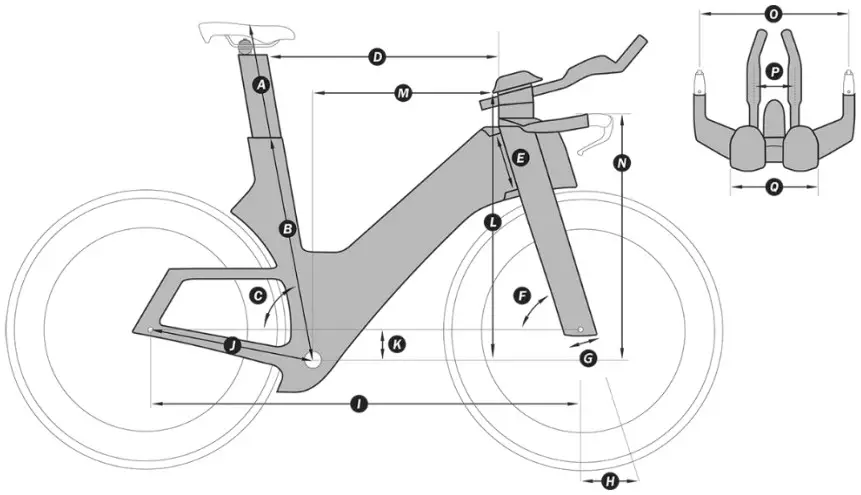
| XXS | XS | S | M | L | ||
| HEIGHT (cm) | 150 – 162 | 156 – 168 | 164 – 176 | 172 – 186 | 180 – 195 | |
| INSEAM (cm) | 62 – 76 | 65 – 80 | 70 – 85 | 75 – 90 | 80 – 98 | |
| A | SADDLE HEIGHT RANGE (mm) | 540-710 | 580-750 | 620-790 | 660-830 | 700-870 |
| B | SEAT TUBE LENGTH (mm) | 440 | 475 | 510 | 545 | 580 |
| C | SEAT TUBE ANGLE | 76 – 80° | 76 – 80° | 76 – 80° | 76 – 80° | 76 – 80° |
| D | TOP TUBE LENGTH (mm) | 475 | 495 | 520 | 550 | 580 |
| E | HEAD TUBE LENGTH (mm) | 70 | 95 | 120 | 145 | 170 |
| F | HEAD TUBE ANGLE | 71.0° | 73.0° | 73.0° | 73.0° | 73.0° |
| G | FORK RAKE (mm) | 40 | 40 | 40 | 40 | 40 |
| H | TRAIL (mm) | 76.1 | 63.3 | 63.3 | 63.3 | 63.3 |
| I | WHEELBASE (mm) | 968 | 976 | 1005 | 1039 | 1072 |
| J | CHAIN STAY LENGTH (mm) | 405 | 405 | 405 | 405 | 405 |
| K | BOTTOM BRACKET DROP (mm) | 80 | 80 | 77 | 74 | 74 |
| L | ARMREST STACK (15D) (mm) | 545 – 615 | 575 – 645 | 595 – 665 | 615 – 685 | 640 – 710 |
| M | ARMREST REACH (15D) (mm) | 340 – 430 | 355 – 445 | 375 – 465 | 400 – 490 | 425 – 515 |
| FRAME STACK (mm) | 483 | 513 | 534 | 555 | 579 | |
| FRAME REACH (mm) | 390 | 405 | 426 | 452 | 478 | |
| N | HEIGHT (mm) | 530 – 570 | 560 – 600 | 580 – 620 | 600 – 640 | 625 – 665 |
| O | HANDLEBAR WIDTH (mm) | 400 | 400 | 400 | 400 | 400 |
| P | EXTENSION WIDTH (mm) | 110 | 190 | 110 | 190 | 110 | 190 | 110 | 190 | 110 | 190 |
| Q | ARMREST WIDTH (mm) | 190 – 310 | 190 – 310 | 190 – 310 | 190 – 310 | 190 – 310 |
| COMPATIBLE SIZE (mm) | 700 x 28C | 700 x 28C | 700 x 28C | 700 x 28C | 700 x 28C |
STACK AND REACH RANGE
FIT DATA CHART 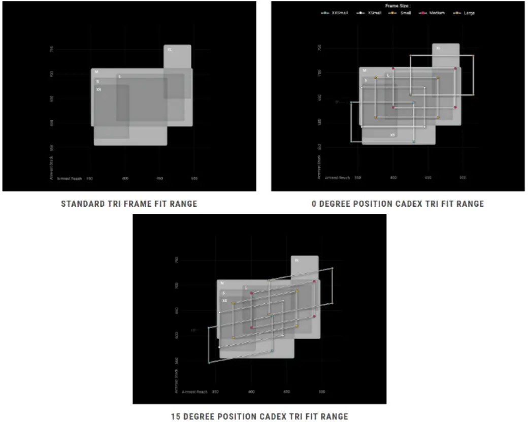 GEOMETRY
| 0° | ||||||
| XXS | XS | S | M | L | ||
| L | ARMREST STACK-MIN (mm) | 560 | 590 | 610 | 630 | 655 |
| L | ARMREST STACK-MAX (mm) | 640 | 670 | 690 | 710 | 735 |
| M | ARMREST REACH-MIN (mm) | 340 | 355 | 375 | 400 | 425 |
| M | ARMREST REACH-MAX (mm) | 430 | 445 | 465 | 490 | 515 |
| 5° | ||||||
| XXS | XS | S | M | L | ||
| L | ARMREST STACK-MIN (mm) | 555 | 585 | 605 | 625 | 650 |
| L | ARMREST STACK-MAX (mm) | 625 | 655 | 675 | 695 | 720 |
| M | ARMREST REACH-MIN (mm) | 340 | 355 | 375 | 400 | 425 |
| M | 430 | 445 | 465 | 490 | 515 | |
| 10° | ||||||
| XXS | XS | S | M | L | ||
| L | ARMREST STACK-MIN (mm) | 550 | 580 | 600 | 620 | 645 |
| L | ARMREST STACK-MAX (mm) | 630 | 660 | 680 | 700 | 725 |
| M | ARMREST REACH-MIN (mm) | 340 | 355 | 375 | 400 | 425 |
| M | ARMREST REACH-MAX (mm) | 430 | 445 | 465 | 490 | 515 |
| 15° | ||||||
| L | ARMREST STACK-MIN (mm) | 545 | 575 | 595 | 615 | 640 |
| L | ARMREST STACK-MAX (mm) | 615 | 645 | 665 | 685 | 710 |
| M | ARMREST REACH-MIN (mm) | 340 | 355 | 375 | 400 | 425 |
| M | ARMREST REACH-MAX (mm) | 430 | 445 | 465 | 490 | 515 |
TRI BAR REMOVAL & ASSEMBLY
REMOVAL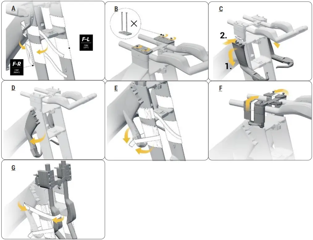
- Install fork pads F-R and F-L onto the upper part of fork (A).
- Loosen but don’t remove the four cockpit fixing bolts with a 4mm hex key (B).
- Lift up the extension assembly and detach base bars from both sides. Install protective spacer to the four fixing bolts. (C).
- Gently flip down both base bars without putting too much tension on the brake hoses. Gently lay each bar against the fork leg on the same side. (D).
- Secure both base bars to the fork legs with the shorter Velcro straps. (E).
- Secure spacers with Velcro straps. Completely loosen the four cockpit fixing bolts. (F).
- Flip the assembly down and position it gently against the front of the fork. Secure the entire assembly with the longer Velcro straps. (G).
ASSEMBLY
NOTE:
Always use a torque wrench.
After assembly, with both wheels on the floor, hold both brakes and gently rock the bike forward and backward to make sure nothing is loose. 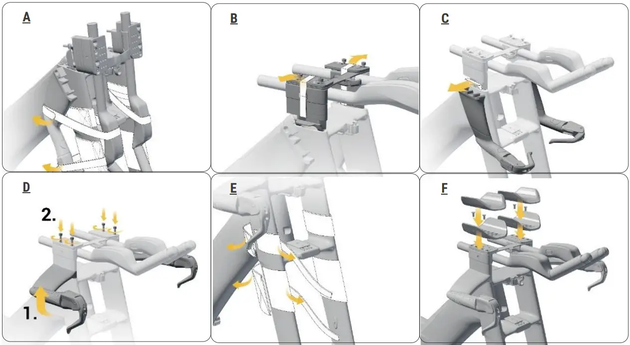
- Remove securing Velcro strap from assembly (A).
- Replace extension bar assembly and loosely refit the four fixing bolts. Remove Velcro straps (B).
- Remove protective spacers. (C).
- Replace base bars. Tighten all cockpit fixing bolts to 5.5Nm with a 4mm hex (D)
- Remove protective pads (E).
- Replace arm cups. Tighten bolts to 4Nm with a 3mm hex (F).
TOP TUBE STORAGE & TOOLKIT REMOVAL & INSTALLATION
NOTE:
Make sure all storage parts fit snugly to the frame and do not rattle.
TOP TUBE STORAGE REMOVAL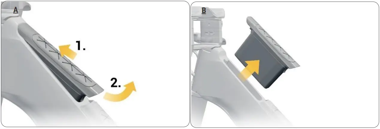
- Hold the lower end firmly and push upwards (A).
- Pivot the storage box upwards to remove. (B).
TOP TUBE STORAGE INSTALLATION 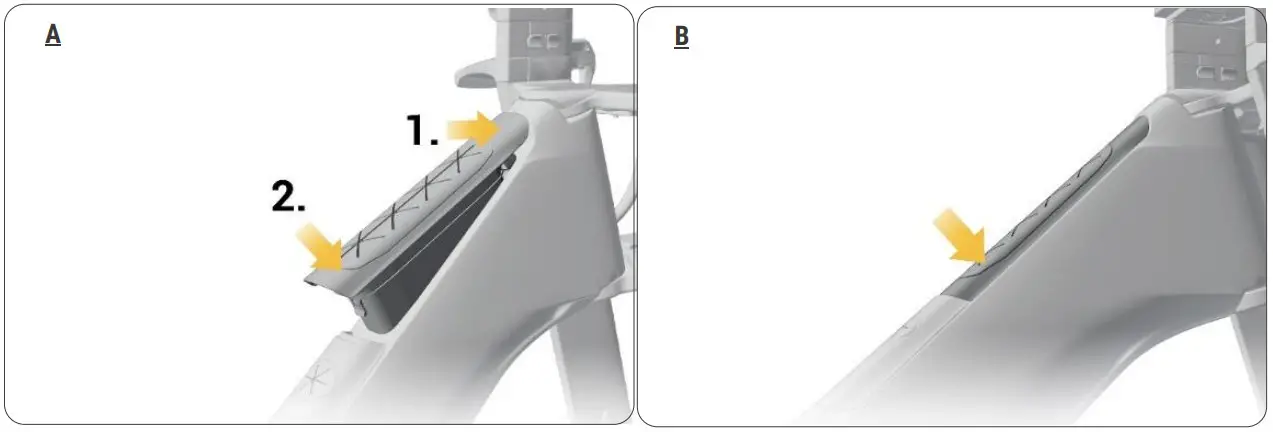
- Insert and firmly push front latch into the frame recess (A).
- Push storage box downward into the frame (B).
TOOLKIT REMOVAL 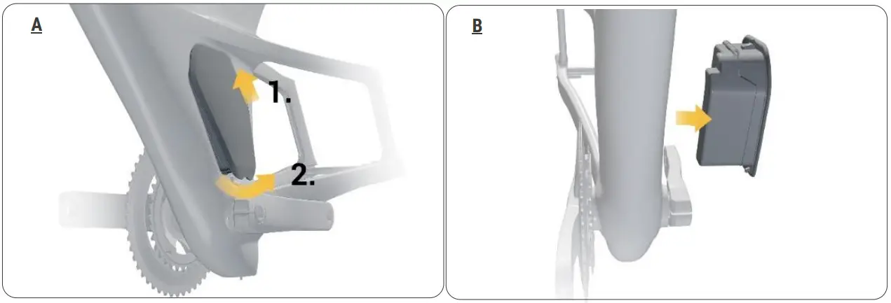
- Hold the lower end firmly and push upwards (A).
- Pivot the toolkit sideways to remove (B).
TOOLKIT INSTALLATION 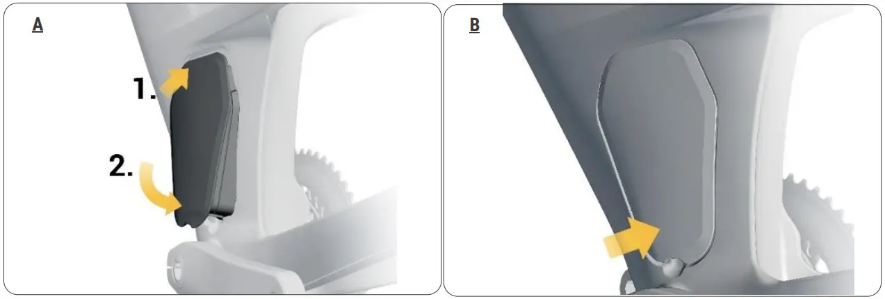
- Insert and firmly push upper latch into the frame recess (A).
- Push tool box into the frame until it fits snugly. (B).
HYDRATION SYSTEM REMOVAL & INSTALLATION
REMOVAL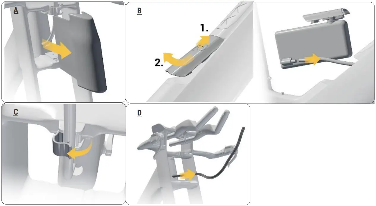
- Remove front aero cover by pulling outward with both hands (A)
- Take out the bladder and disconnect the straw. Replace the bladder (B).
- Use your index finger to unclip the straw while pressing the clip with your thumb (C)
- Remove the straw by gently pulling through from the front side of the bike (D).
INSTALLATION
NOTE:
Once the straw has been refitted, turn the handlebar from side to side to make sure is not compromised. If you feel any interference, remove the straw and refit again.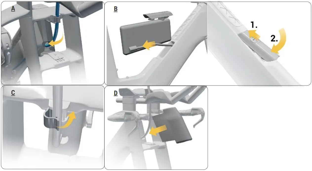
- Feed the straw from the head tube trough the right-side of steerer (A).
- Take out the bladder and reconnect the straw. Replace the bladder (B).
- Adjust the straw to desired length and secure the straw onto the clip (C).
- Refit the front aero cover (D).
SEAT POST & SADDLE ADJUSTMENT
CLAMP POSITION
Front position 78° to 80° seat tube angle 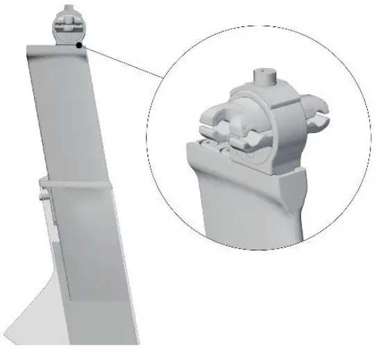 Rear position 76° to 78° seat tube angle
 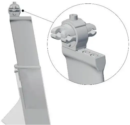 SADDLE CLAMP ADJUSTMENT
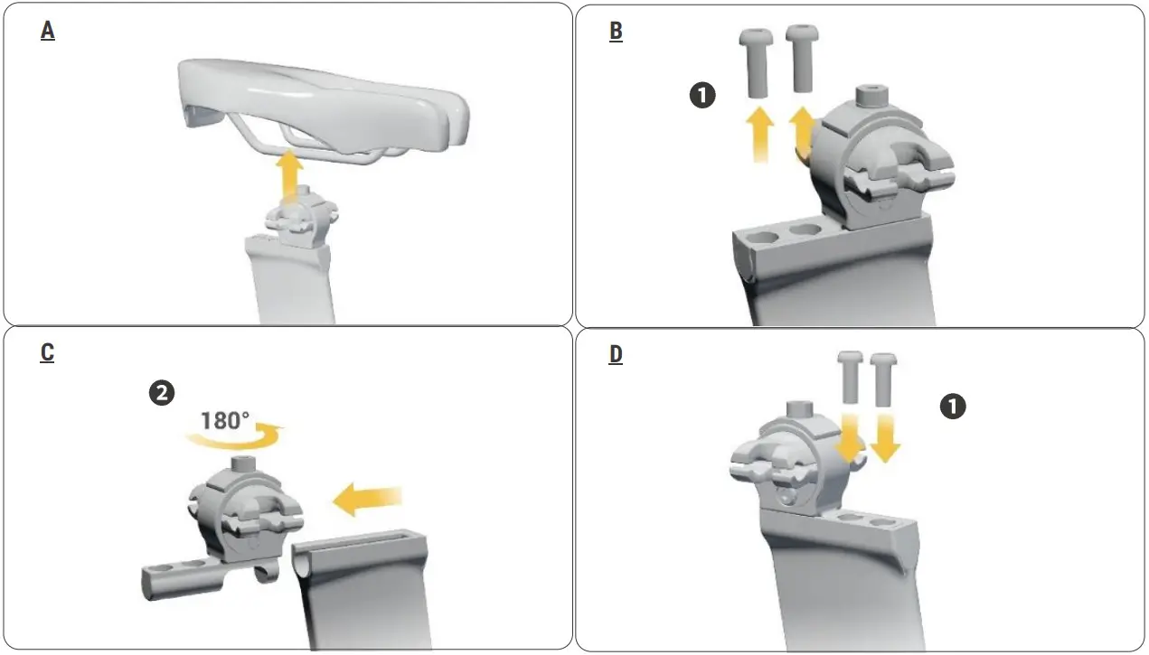
- Remove saddle (A).
- Loosen and remove both clamp fixing bolts 1 (B).
- Pull out clamp 2, turn it 180° horizontally and refit it into seat post (C).
- Replace clamp fixing bolts 1, tighten to 5Nm (D).
SEAT POST
Minimum insertion – 80mm. 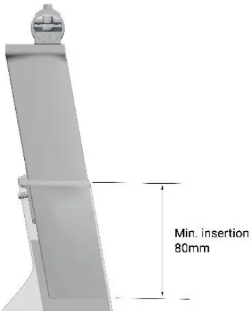 NOTE:
NOTE:
- Always use a torque wrench
- Once the installation or adjustment has been completed, grab the saddle and rock it back and forth to ensure all fasteners are snug.
 SADDLE POSITION ADJUSTMENT
- Loosen the side bolt 1 a full turn; Loosen the top bolt 2 a full turn (A)
- Adjust saddle angle, fore or aft to preferred position (B).
- Tighten the top bolt to 5 Nm with 4 mm hex; Tighten the side bolt to 5 Nm with 4 mm hex (C)
- Double check clamp fixing bolts ➌ (D)
SADDLE REMOVAL & INSTALLATION 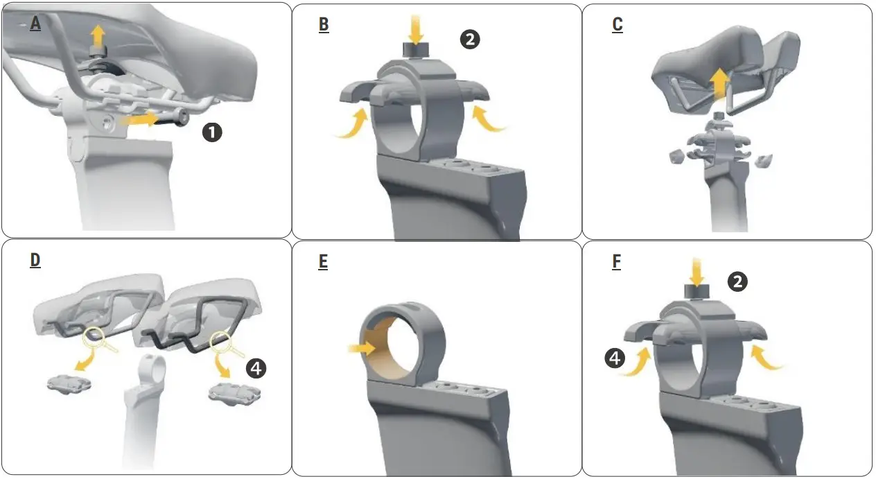
- Loosen and remove the side bolt 1 (A).
- Loosen and remove the top bolt 2 and the upper piece (B).
- Remove the saddle from the clamp. Rock the saddle back and forth to help removal. (C).
- Select 7mm top clamp for alloy rail saddle or 9mm top clamp for carbon rail saddle. ➍ (D)
- Apply carbon paste to the clamp housing (E).
- Replace top clamp ➍ and loosely tighten the top bolt 2 and upper piece (F).

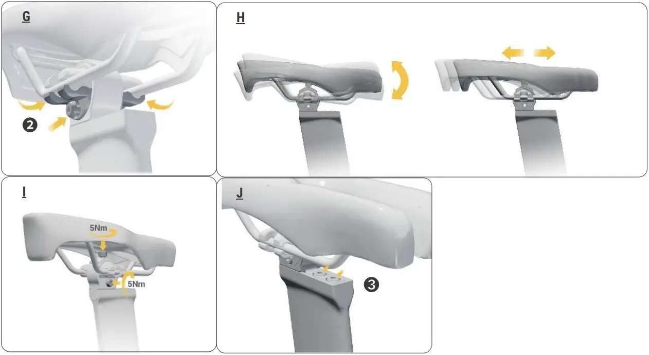
- Refit saddle with the lower piece and lightly tighten the side bolt 2 (G)
- Adjust saddle angle, fore and aft to preferred position (H).
- Tighten the top bolt and the side bolt to 5 Nm (I)
- Double check clamp fixing bolts ➌ (J)
![]()


