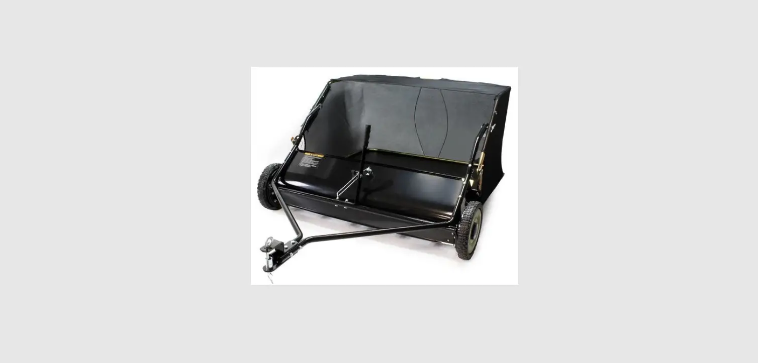
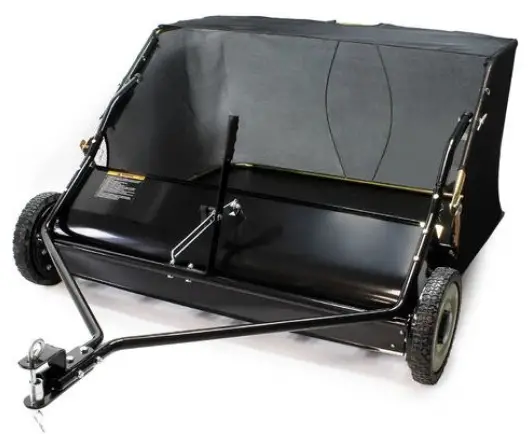
WILTEC 51701 Lawn Sweeper
Read and follow the operating instructions and safety information before using for the first time. Technical changes reserved! Due to further developments, illustrations, functioning steps, and technical data can differ insignificantly. Updating the documentation If you have suggestions for improvement or have found any irregularities, please contact us.
Introduction
Thank you for purchasing this quality product. To minimize the risk of injury we urge that our clients take some basic safety precautions when using this device. Please read the operation instructions carefully and make sure you have understood its content. Keep these operation instructions safe.
Safety instructions
Remember that any power equipment can cause injury if operated improperly, or if the user does not understand how to operate the equipment. Always be cautious when using power equipment.
- Read the vehicle and sweeper owner manual and know how to operate your vehicle and sweeper before using the sweeper attachment. Always instruct other users before they operate the sweeper.
- Do not permit children to operate the sweeper.
- Do not permit anyone to ride on the sweeper.
- Never attach the hopper rope to any part of your body or clothing! Never hold onto the rope while towing the sweeper! Attached the rope to the towing vehicle to keep it away from wheels and rotating parts.
- Operate the sweeper at reduced speed on rough terrain, near ditches and on hillsides to prevent loss of control.
- Speed limit: maximum speed is 9 km⁄h (6 mph).
- This sweeper is not designed for street or highway use. Watch for traffic when sweeping near roadways.
- This product may be used for lawn sweeping and may collect leaves, branches, etc.; it is not designed for heavy and sharp garbage like stones or steel objects.
- Do not exceed the maximum capacity of the hopper.
- Vehicle braking and stability may be affected with the attachment of this sweeper. Do not fill the sweeper to its maximum capacity without checking the capability of the towing vehicle to safely pull and stop with the sweeper attached. Stay off steep slopes.
- Stop and inspect the vehicle and the sweeper for damage after striking an object. Repair any damage before continuing the operation.
- Keep the sweeper away from fire. The hopper bag and its content could burn.
- Before storing the sweeper, always empty the hopper bag to avoid spontaneous combustion.
- Make sure the sweeper will not be used in the conditions of bad weather such as strong wind, high air pressure, etc.
- Please replace the hopper when it is worn out; keeping using a damaged hopper may be dan-gerous.
- Axle lubrication needs to be added before each usage.
Scope of delivery (loose parts)
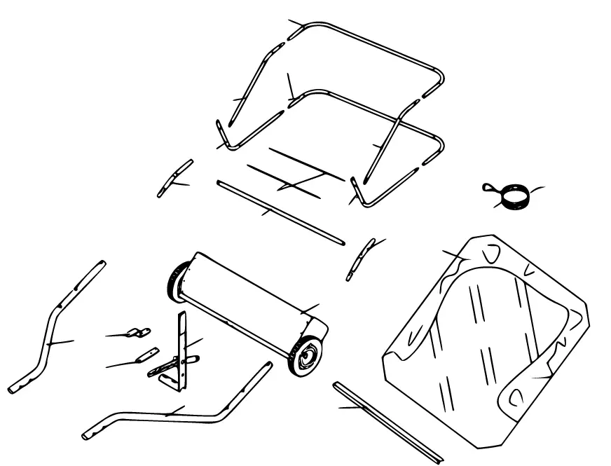
Main components
| № | Name | № | Name |
| 1 | Right hand hitch tube | 9 | Bag arm tube (2) |
| 2 | Left hand hitch tube | 10 | Bag frame strap |
| 3 | Handle assembly | 11 | Hopper support rod (2) |
| 4 | Straight hitch bracket | 12 | Lower hopper side tube (2) |
| 5 | Angled hitch bracket | 13 | Rear hopper tube (2) |
| 6 | Hopper bag | 14 | Upper hopper side tube (2) |
| 7 | Connecting rod | 15 | Rope |
| 8 | Sweeper housing assembly |
Screwing material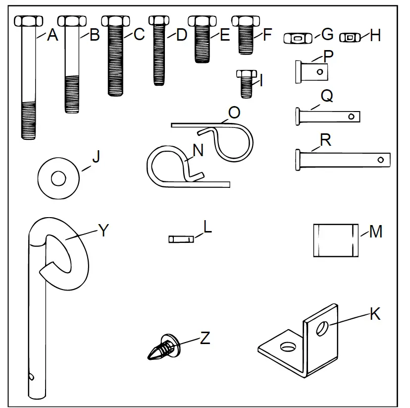
| Letter | Qty. | Name | Letter | Qty. | Name |
| A | 2 | Hexagonal bolt M8×65 | K | 1 | Angle bracket |
| B | 2 | Hexagonal bolt M8×50 | L | 1 | Adjustable pole spacer |
| C | 2 | Hexagonal bolt M8×40 | M | 2 | Hitch spacer |
| D | 4 | Hexagonal bolt M6×40 | N | 5 | R pin ⌀3 |
| E | 1 | Hexagonal bolt M8×20 | O | 4 | R pin ⌀2 |
| F | 1 | Hexagonal bolt M8×16 | P | 2 | Clevis pin ⌀9.5×25 |
| G | 8 | Nylon lock nut M8 | Q | 4 | Clevis pin ⌀6×37 |
| H | 6 | Nylon lock nut M6 | R | 2 | Clevis pin ⌀8×59.5 |
| I | 2 | Hexagonal bolt M6×12 | Y | 1 | Hitch pin |
| J | 1 | Big flat washer ⌀8 | Z | 4 | Plastic plug |
Assembly
REMOVE THE HARDWARE PACK AND ALL LOOSE PARTS FROM THE BOX AND VERIFY THAT ALL THE PARTS AND FASTENERS SHOWN ON THE LAST PAGE ARE INCLUDED.
Sweeper assembly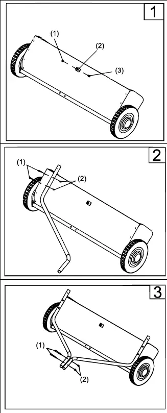
Note: Right hand (R. H.) and left hand (L. H.) are determined from the operator’s position on the tractor.
- fig. 1: Connect the angle bracket to the sweeper housing us-ing a M8×16 hex bolt and a M8 hex lock nut. Make sure that the bracket is turned as shown and aligned straight with the hous-ing, then tighten.
- fig. 2: Assemble the R. H. hitch tube to the sweeper housing using a M6×40 hex bolt and a M6 lock nut. Do not tighten yet.
- Repeat for the L. H. hitch tube.
- fig. 3: Fasten the hitch tubes together using two M8×65 hex bolts and M8 lock nuts. Do not tighten yet.
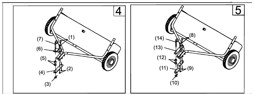
The tractor hitch ground clearance determines how to proceed:- clearance from 279 to 330 mm > fig. 4
- clearance from 203 to 279 mm > fig. 5
- fig. 4 u. 5: Assemble the hitch brackets to the hitch tubes using two M8×50 hex bolts and M8 hex lock nuts. The bolts should straddle the front hitch tube bolt. Do not tighten yet.
- Now tighten the four bolts fastening the hitch tubes to the sweeper housing. Next tighten the two bolts fastening the ends of the hitch tubes together. Finally tighten the two bolts fastening the hitch brackets to the hitch tubes.
- Assemble the hitch pin, spacers, and hair cotter pin to the hitch brackets.
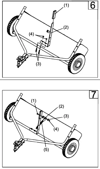
- fig. 6: Assemble the height adjustment handle to the height adjustment tube as shown in the fig. Use two M8×40 hex bolts and M8 lock nuts. Do not tighten yet.
- fig. 7: Insert a M8×20 hex bolt through the angle bracket. As-semble onto the bolt (in order) the spacer bushing, the height adjustment strap, a ⌀8 big flat washer and a M8 hex lock nut. Tighten.
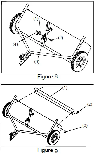
- fig. 8: Position the height adjustment handle side to side so that the external teeth washer can fit between the handle and the height adjustment strap. Tighten the nuts securing the height adjustment handle.
- fig. 9: Assemble the connecting rod to the sweeper housing by using two sets of M6×12 hex bolt and M6 lock nut.
Hopper bag assembly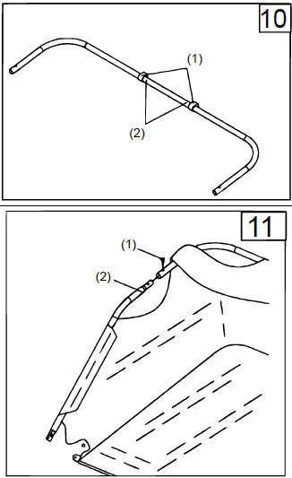
- fig. 10: Turn a rear hopper tube so that the brace holes in the middle of the tube face down. Slide the tube through the two loops sewn to the top rear seam inside the hopper bag.
- fig. 11: Insert the two upper hopper side tubes through the flaps stitched on each side of the hopper bag.
- Assemble the ends of the rear hopper tube onto the ends of the upper hopper side tubes.
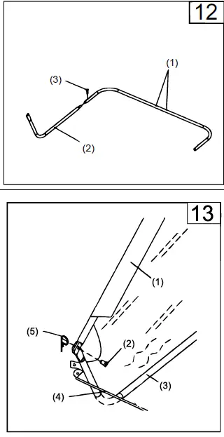
- fig. 12: Turn the second rear hopper tube so that the brace holes in the middle of the tube face up. Assemble the ends of the rear hopper tube onto the ends of the lower hopper side tubes. Fasten together using plastic plugs.
- fig. 13: Place the assembled low hopper tubes into the bot-tom of the hopper bag.
- Attach the ends of the lower hopper side tubes to the inside of the upper side tubes using two ⌀9.5×25 clevis pins inserted from the inside, and two hair cotter pins ⌀3.
- fig. 14: Insert the bag frame strap into the stitched sleeve along the front edge of the bag bottom.
- Assemble the bag frame strap to the lower hopper side tubes using two ⌀6×37 clevis pins and two ⌀2 hair cotter pins.
- fig. 15: Secure the bag corners around the lower hopper side tubes by snapping the bag flaps to the bag bottom on both sides.
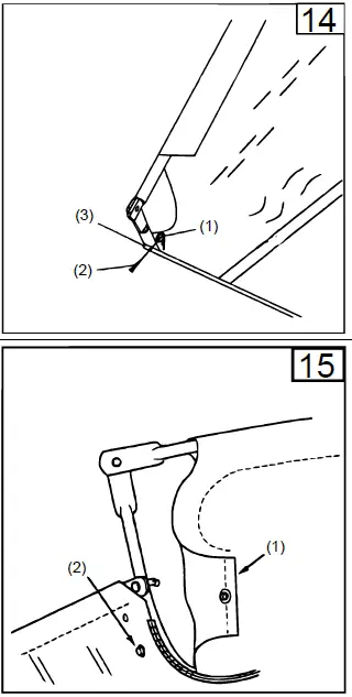
- fig. 16: Tip the hopper onto its back to assemble the two hopper support rods (1). Place the ends of each rod into the up-per and lower rear hopper tubes bending the rod just enough to fit it into the holes in the tubes.
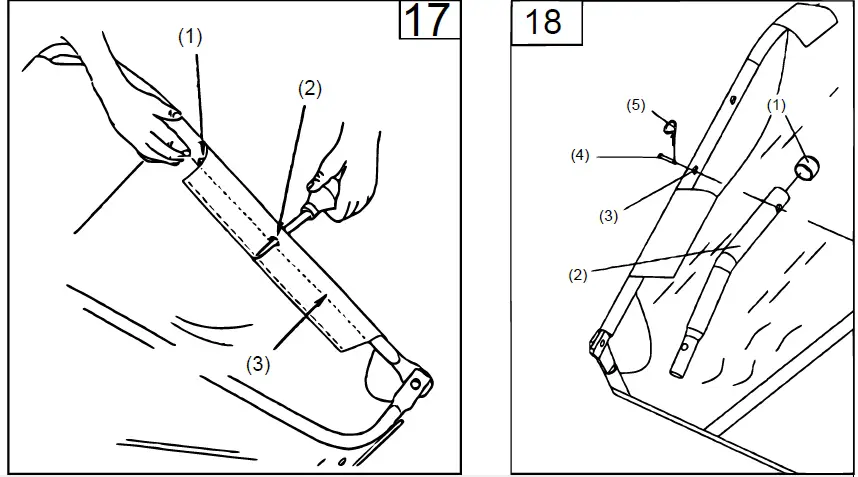
- fig. 17: Feel along the stitched flap on the hopper bag to locate the lower hole in each upper hopper side tube. Place a hole through both sides of the stitched flaps in alignment with the lower hole.
- fig. 18: Insert a ⌀8×59.5 clevis pin through the lower hole in each upper hopper side tube. Next assemble a bag arm tube onto each clevis pin and secure it with a ⌀3 hair cotter pin.
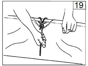
- fig. 19: Secure the rope to the top centre of the hopper bag frame.
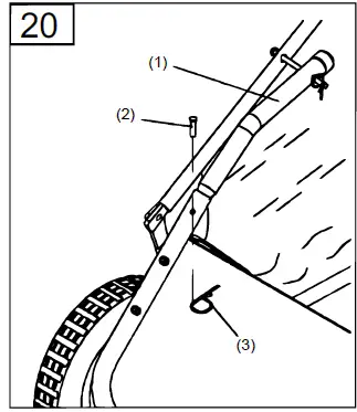
- fig. 20: To assemble the hopper bag to the sweeper, slide the ends of the bag arm tubes into the ends of the sweeper hitch tubes and secure them with two ⌀6×37 clevis pins and ⌀2 hair cotter pins.
Technical specifications
| Item number | 51701 | 51702 | 51703 |
| Dimensions (㎝) | 180 × 115 × 70 | 180 × 120 × 55 | approx. 180 × 129 × 55 |
| Weight (㎏) | 31,5 | 35 | 43 |
| Running wheel (㎜) | 260 × 44,5 | 260 × 44,5 | 275 × 44,5 |
| Sweeping width (㎝) | approx. 95 | approx. 105 | approx. 120 |
| Capacity (ℓ) | approx. 320 | approx. 350 | approx. 480 |
Explosion view and parts list
| № | Name | Qty. | № | Name | Qty. |
| 1 | Hopper rope | 1 | 40 | Connecting rod | 1 |
| 2 | Vinyl cap | 2 | 41 | Hexagonal bolt M6×12 | 2 |
| 3 | Rear hopper frame tube | 2 | 42 | Dust cover retainer | 2 |
| 4 | Bag frame strap | 1 | 43 | Inside star washer | 2 |
| 5 | Hopper support rod | 2 | 44 | Brush shaft bushing | 2 |
| 6 | Hopper bag | 1 | 45 | Spacer bushing | 2 |
| 7 | Lock washer ⌀10 | 2 | 46 | Axle spacer | 2 |
| 9 | Hexagonal bolt M8×16 | 5 | 47 | Plastic bolt | 4 |
| 10 | Angled bracket | 1 | 48 | Star washer ⌀5 | 6 |
| 11 | Bag arm tube | 2 | 49 | Clevis pin C | 2 |
| 12 | Lower hopper frame tube | 2 | 50 | L. H. end plate | 1 |
| 13 | Hexagonal bolt M8×40 | 2 | 51 | Special washer | 2 |
| 14 | Upper hopper frame tube | 2 | 52 | Bushing | 2 |
| 15 | Height adjusting grip | 1 | 53 | Retaining ring ⌀15 | 4 |
| 16 | Lock nut M6 | 18 | 54 | Adjustable washer A | 4 |
| 17 | Height adjusting handle | 1 | 55 | Adjustable washer C | 2 |
| 18 | Carriage bolt M8×30 | 1 | 56 | Dowel pin (drive) | 2 |
| 19 | Brush shaft | 1 | 57 | L. H. pinion gear | 1 |
| 20 | Brush | 4 | 58 | Adjustable washer B | 2 |
| 21 | Wrapper | 1 | 59 | Clevis pin D | 2 |
| 22 | R. H. end plate | 1 | 60 | Wheel and tyre assembly | 2 |
| 23 | R. H. pinion gear | 1 | 61 | Wheel bushing | 4 |
| 24 | Dust cover assembly | 2 | 62 | Hexagonal bolt M8×65 | 2 |
| 25 | Height adjustment tube assembly | 1 | 63 | Hexagonal bolt M8×50 | 2 |
| 26 | Clevis pin ⌀6×37 | 4 | 64 | Hub cap | 2 |
| 27 | Wing knob | 1 | 65 | Hexagonal bolt M6×40 | 4 |
| 28 | External teeth washer | 1 | 66 | Spacer bushing to 32 | 1 |
| 29 | Hexagonal lock nut M8 | 12 | 67 | Nylon lock nut M10 | 2 |
| 30 | Slotted pan head screw M5×12 | 14 | 68 | Hexagonal bolt M5×25 | 6 |
| 31 | Retainer brush | 6 | 69 | Big flat washer ⌀8 | 1 |
| 32 | Height adjustment strap | 1 | 70 | Hexagonal bolt M6×20 | 12 |
| 33 | R. H. hitch tube | 1 | 71 | Retainer brush | 12 |
| 34 | Hitch bracket | 1 | 72 | Hitch pin | 1 |
| 35 | Straight hitch bracket | 1 | 73 | Cotter bearing | 1 |
| 36 | L. H. hitch tube | 1 | 74 | R pin ⌀3 | 5 |
| 37 | Big flat washer ⌀10 | 4 | 75 | R pin ⌀2 | 4 |
| 38 | Hexagonal bolt M10×85 | 2 | 76 | Big flat washer | 1 |
| 39 | Nylon lock nut M5 | 20 | 77 | Hexagonal bolt M8×20 | 1 |
Important notice: The reprint or reproduction, even of excerpts, and any commercial use, even in part, of this instruction manual require the written permission of WilTec Wildanger Technik GmbH. The information contained in this document may alter at any time without previous notice. It is prohibited to copy or spread any parts of this document in any way without prior written allowance. All rights re-served. The WilTec Wildanger Technik GmbH cannot be held accountable for any possible mistakes in this operating manual, nor in the diagrams and figures shown. Even though, the WilTec Wildanger Technik GmbH has undergone biggest possible efforts to ensure that the operating manual is complete, faultless, and up to date, mistakes cannot be entirely avoided. If you should find a mistake or wish to make a suggestion for improvement, we look forward to hearing from you.
Send an e-mail to:
[email protected]
or use our contact form:
https://www.wiltec.de/contacts/
The most recent version of this manual in various languages can be found in our online shop via:
https://www.wiltec.de/docsearch
Our postal address is:
WilTec Wildanger Technik GmbH
Königsbenden 12
52249 Eschweiler
Germany
Do you wish to pick goods up? Our pick-up address is:
WilTec Wildanger Technik GmbH
Königsbenden 28
52249 Eschweiler
Germany
To shorten the waiting time and allow for a rapid on-site transaction, we ask you to call us previously or place your order via the webshop.
E-mail: [email protected]
Tel: +49 2403 55592–0
Fax: +49 2403 55592–15
To return orders for exchange, repair, or other purposes, please use the following address. Attention! To allow for smooth execution of your complaint or return, it is important to contact our customer service team before returning the goods.
Returns Department
WilTec Wildanger Technik GmbH
Königsbenden 28
52249 Eschweiler
E-mail: [email protected]
Tel: +49 2403 55592–0
Fax: +49 2403 55592–15


