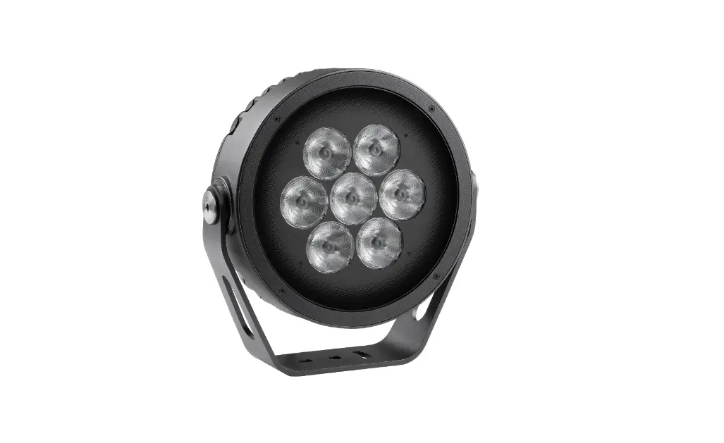
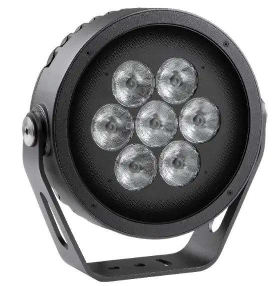
Anolis Calumma M MC LED Lighting
QR code for user manual

FOR YOUR OWN SAFETY, PLEASE READ THIS USER MANUAL CAREFULLY BEFORE POWERING OR INSTALLING YOUR Calumma !Save it for future reference.
This device has left our premises in absolutely perfect condition. In order to maintain this condition and to ensure safe operation, it is absolutely necessary for the user to follow the safety instructions and warnings written in this manual.
The manufacturer will not accept liability for any resulting damages caused by the non-observance of this manual or any unauthorized modification to the device.
Unauthorized modification will void warranty.
Safety instructions
DANGEROUS VOLTAGE CONSTITUTING A RISK OF ELECTRIC SHOCK IS PRESENT WITHIN THIS UNIT!
This fixture should be operated only from the type of power source indicated on the marking label. If you are not sure of the type of power supplied, consult your authorized distributor or local power company.
Always disconnect the fixture from AC power before servicing or cleaning.
Make sure the power/data cable is not damaged by sharp edges.
Do not install the unit near an open flame.
Refer servicing to qualified service personnel.
This fixture falls under protection class I. Therefore this fixture has to be connected to a mains socket outlet with a protective earthing connection.
Do not connect this fixture to a dimmer pack.
LED light emission. Risk of eye injury. Do not look into the beam from a short distance without suitable protective eyewear. Do not look at LEDs with magnifiers or similar optical instruments that may concentrate the light output.
The fixture was designed for outdoor use. This fixture must not be used for underwater installation.
When choosing the installation spot, please make sure that the fixture is not exposed to extreme heat or dust. Avoid using the unit in locations subject to possible impacts.
The fixture body never must be covered with cloth or other materials when the fixture is under operation.
Only operate the fixture after having checked that the housing is firmly closed and all screws are tightly fastened.
The fixture becomes hot during operation. Allow the fixture to cool approximately 30 minutes prior to servicing or maintenance.
Operate the fixture only after having familiarized yourself with its functions. Do not permit operation by persons not qualified to operate the fixture. Most damages are the result of unprofessional operation!
Immunity of the equipment is designed for electromagnetic environments E1, E2, E3 according to the standard EN55103-2 ed.2 Electromagnetic compatibility. Product family standard for audio, video, audiovisual and entertainment lighting control apparatus for professional use. Part 2: Immunity.
The product (covers and cables) must not be exposed to a high frequency electromagnetic field higher than 3V/m.
The installation company should check levels of possible interferences above the tested levels E1,E2,E3 given by this standard (e.g. transmitters in surrounding area) before installing the equipment.
Emission of the equipment complies with the standard EN55032 Electromagnetic compatibility of multimedia equipment – Emission Requirements according to class B.
Please consider that unauthorized modifications on the fixture are forbidden due to safety reasons!
Please use the original packaging if the fixture is to be transported.
If this device will be operated in any way different to the one described in this manual, the product may suffer damages and the warranty becomes void. Furthermore, any other operation may lead to dangers like short-circuit, burns, electric shock etc.
Fixture exterior view
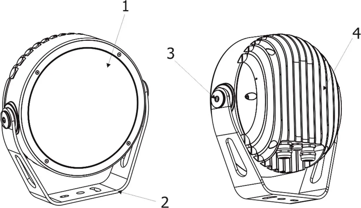
- Transparent glass cover
- Mounting yoke
- Tilt adjusting lock
- LED module with heat sink
Installation
Mounting the fixture
The Calumma can be fastened in any orientation on a flat, non-flammable surface by means of mounting yoke (2).
The LED module (4) can be tilted +180°/-180°. Use an Allen key 2.5 for adjusting a LED module position.
Ensure that the structure to which you are attaching the fixture is secure.
Connection to mains
The unit must be installed by a qualified electrician in accordance with all national and local electrical and construction codes and regulations.
This device falls under class one and must be grounded!
The Calumma is equipped with auto-switching power supply that automatically adjusts to any 50/60Hz AC power source from 120-277 Volts.
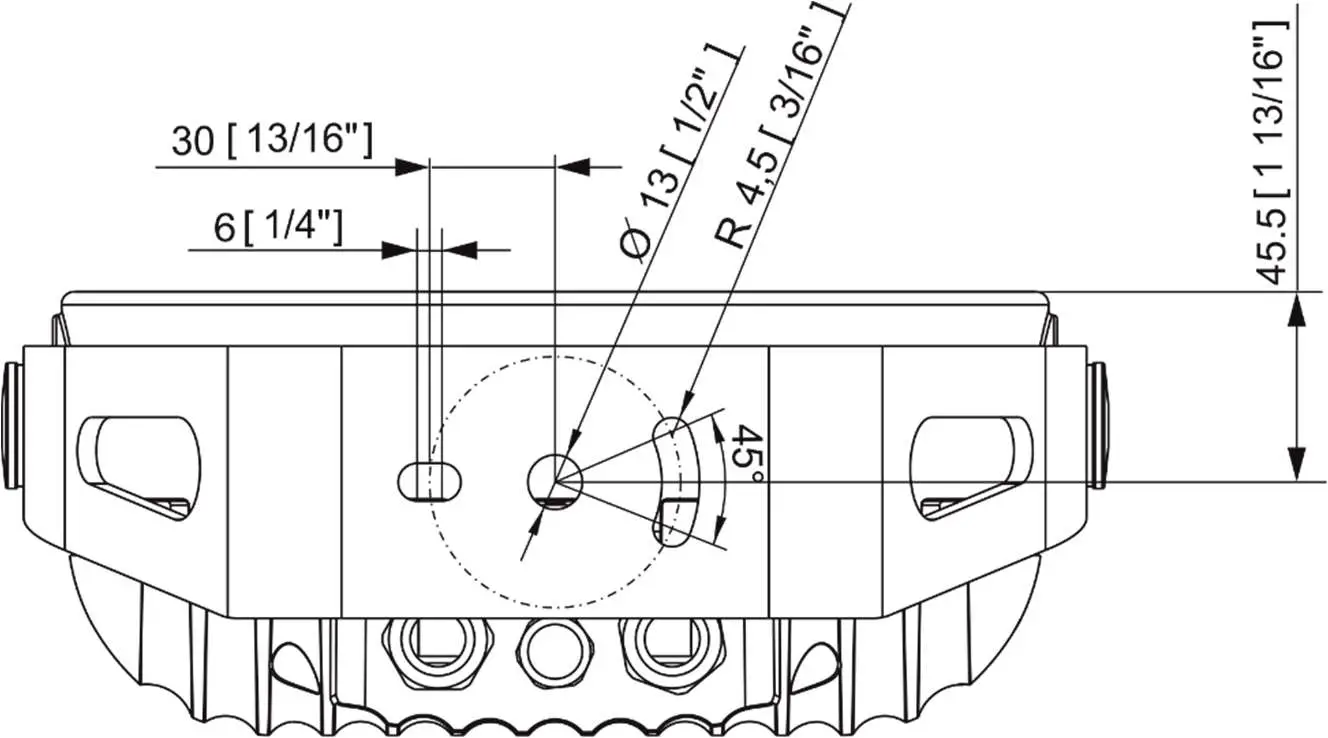
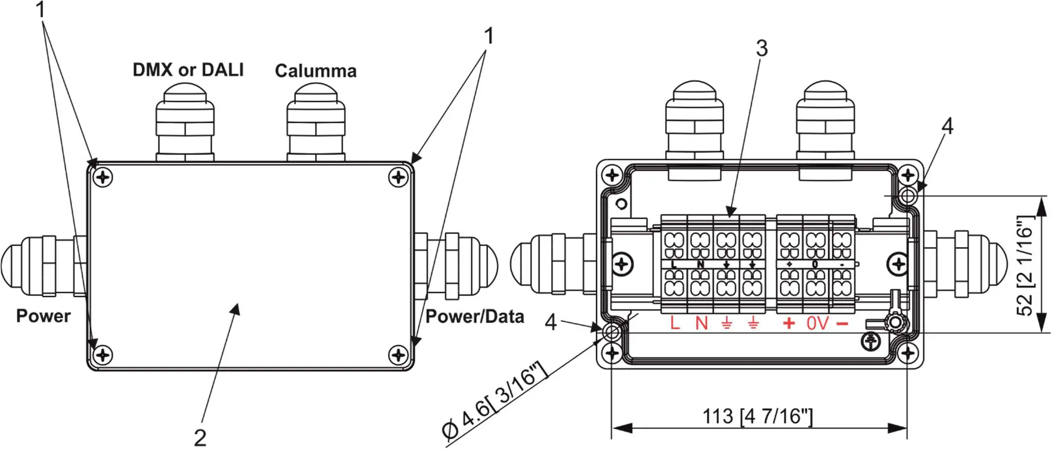
Junction box installation
The junction box box falls under protection class I . Therefore, every junction box has to be connected to a mains socket outlet with a protective earthing connection.
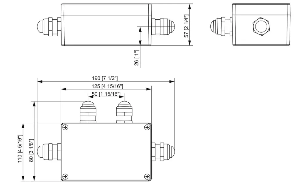
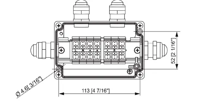
- Unscrew the four screws (1) from the cover (2) on the junction box to get access to the terminal block (3) and two mounting holes of diameter of 4.6 mm (4).
- Screw the junction box on a non-flammable flat surface.

- Connect cables.
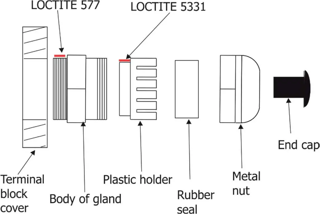
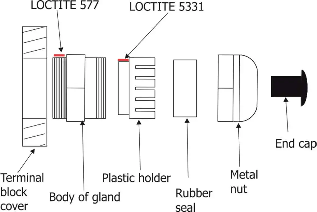
The cable gland M20 x 1.5 with a standard seal serves for a cable of diameter of 7-13mm, for smaller diameter of cable (4-8mm) you have to remove the original seal from the cable gland M20x1.5 and use the enclosed reducing seal instead of it. The reducing seal for diameter of cable 4-8mm (P/N 13051388) is enclosed in the Junction box. Remove the end cap from the cable gland before passing the cable.
We recommend to apply an adequate layer of the paste LOCTITE 5331 on the plastic holder of the cable gland before inserting it into the body of the gland and an adequate layer of the paste LOCTITE 577 on the thread of the gland body.
Cable gland M20x1.5:
- Screw the cover (2) back on the junction box.
Top hat installation
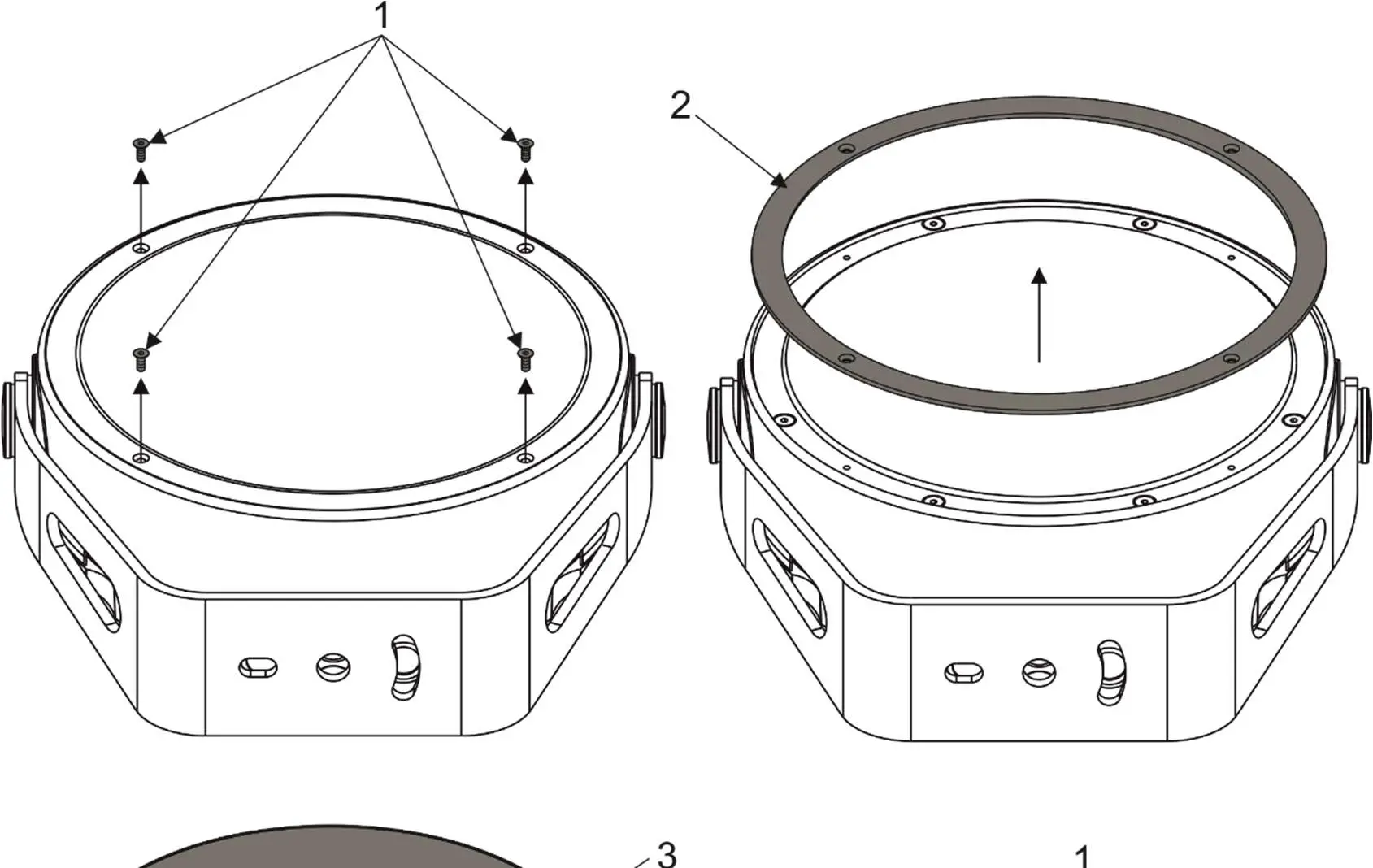
- Unscrew the four flat-head screws M3x8 (1) from the front of the Calumma and remove the flange (2).
- Place the top hat (3) on the Calumma and screw it by means of the four flat-head screws M3x8 (1).

Half top hat installation
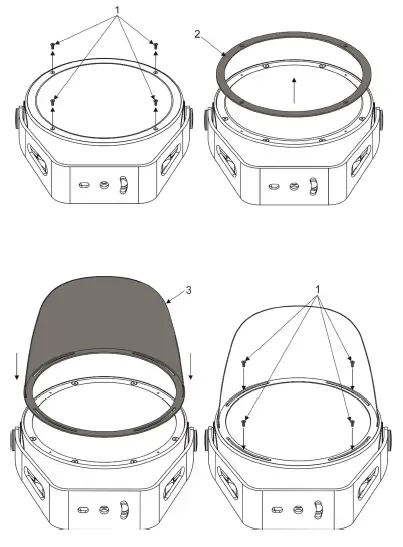
- Unscrew the four flat-head screws M3x8 (1) from the front of the Calumma and remove the flange (2).
- Place the half top hat (3) on the Calumma and screw it by means of the four flat-head screws M3x8 (1).
Control and connection options
DMX or DALI
Example
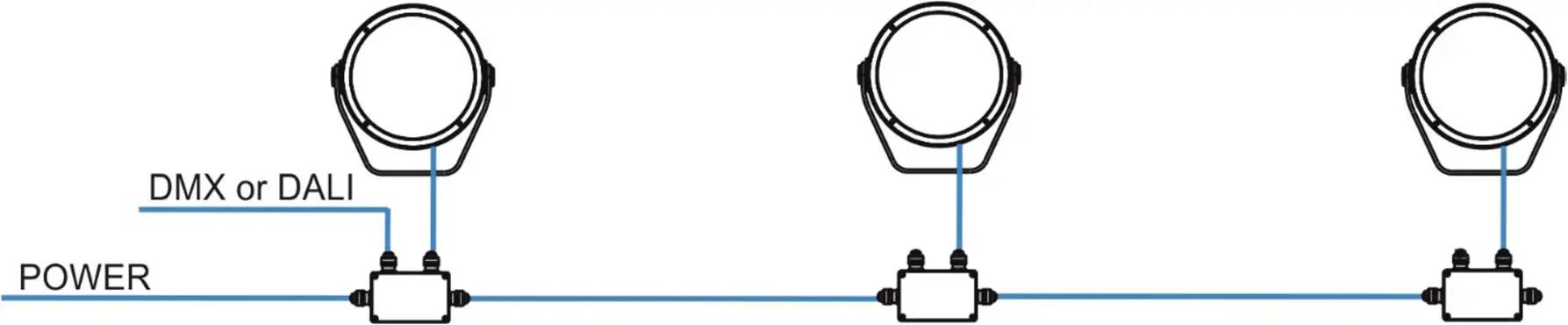
DMX connection (CE)
IF the 5-cored cable Flamar 3x AWG 16 + 1x (2x AWG 24), (P/N 1305 1508) is used for Calumma connection and connection among junction boxes:
| Core | Connection | Core | Connection |
| Black | Live (L) | Red | Data + (+) |
| Blue | Neutral (N) | White | Data – (-) |
| Yellow/Green | GND
| Shielding | Data ground (0V) |
Up to 32 Calummas can be connected in DMX chain.
DALI connection
IF the 5-cored cable SJTW 5x 14AWG (P/N 1305 3336) is used for Calumma connection and connection among junction boxes:
Up to 64 Calummas can be connected in DALI network.
| Core | Connection | Core | Connection |
| Black | Live (L) | Red | Data |
| White | Neutral (N) | Orange | Data |
| Yellow/Green | GND |
Wireless
DMX Example
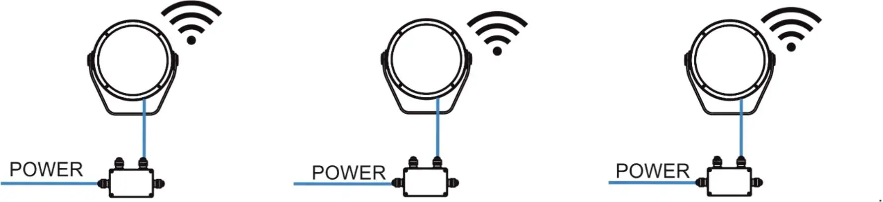
Note: This type of connection is available for M, L, XL versions.
DMX connection (CE)
IF the 5-cored cable Flamar 3x AWG 16 + 1x (2x AWG 24), (P/N 1305 1508) is used for Calumma connection:
| Core | Connection | Core | Connection |
| Black | Live (L) | Red | Data + (+) |
| Blue | Neutral (N) | White | Data – (-) |
| Yellow/Green | GND | Shielding | Data ground (0V) |
DMX connection (US)
IF the 6-cored cable SJTW 6x 14AWG, (P/N 1305 3480) is used for Calumma connection:
| Core | Connection | Core | Connection |
| Black | Live (L) | Red | Data + (+) |
| White | Neutral (N) | Orange | Data – (-) |
| Yellow/Green | GND | Blue | Data ground (0V) |
Wireless DMX to wire DMX
Example
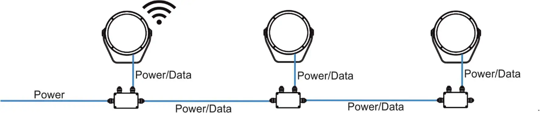
Note: This type of connection must have M, L or XL versions as the first luminaire. Next luminaires in a row could be chosen from S, M, L or XL versions.
DMX connection (CE)
IF the 5-cored cable Flamar 3x AWG 16 + 1x (2x AWG 24), (P/N 1305 1508) is used for Calumma connection and connection among junction boxes:
| Core | Connection | Core | Connection |
| Black | Live (L) | Red | Data + (+) |
| Blue | Neutral (N) | White | Data – (-) |
| Yellow/Green | GND | Shielding | Data ground (0V) |
Up to 32 Calummas M can be connected in DMX chain.
DMX connection (US)
IF the 6-cored cable SJTW 6x 14AWG, (P/N 1305 3480) is used for Calumma connection and connection among junction boxes:
| Core | Connection | Core | Connection |
| Black | Live (L) | Red | Data + (+) |
| White | Neutral (N) | Orange | Data – (-) |
| Yellow/Green | GND | Blue | Data ground (0V) |
Power On/Off
Note: This type of connection is available for Pure White version only. Non dimmable.
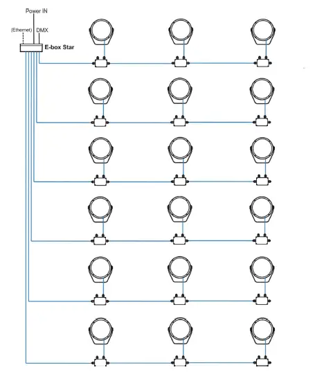
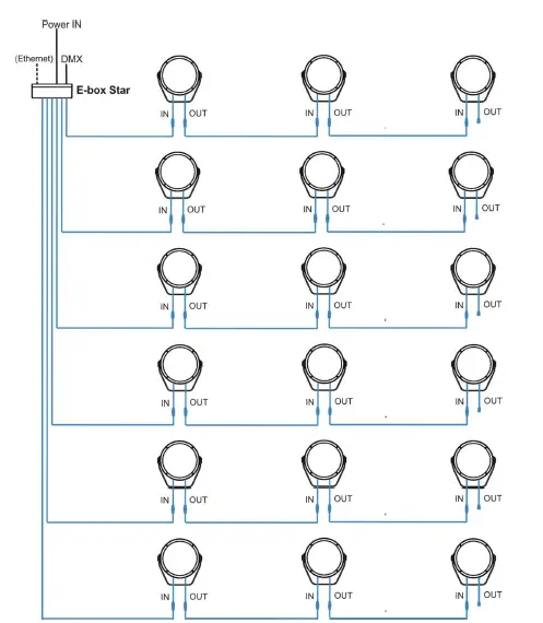
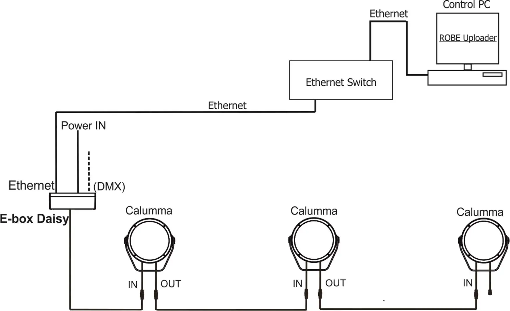
DMX or Ethernet via E-box
The E-box menu allows you to switch connected Calummas to the two modes:
Standard – LED modules are switched to an internal serial connection. DMX addressing of connected LED modules is made automatically (default DMX address = 1, changes can be done by the E-box menu or by RDM)..
Pass-Thr – (Pass through). LED modules are switched to an internal parallel connection. DMX addressing of connected LED modules has to be done manually by means of the Robe Universal Interface (or its wireless version Robe Universal Interface WTX) and the software RDM Manager.
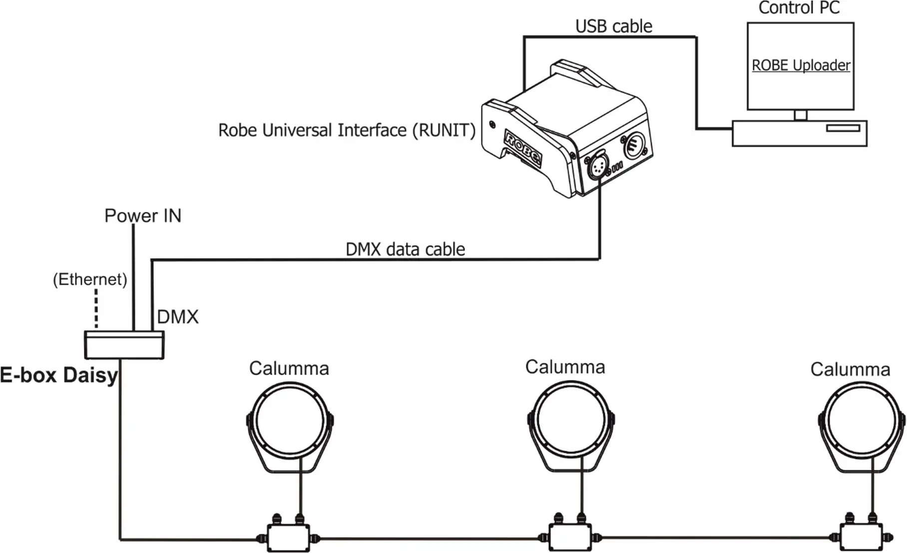
Example with junction boxes
Pass Through mode is intended for this connection. Max. 32 fixtures can be connected to one LED output of the E-Box (Star, Daisy, Lite) in this mode.
CE version
IF the 5-cored cable Flamar 3x AWG 16 + 1x (2x AWG 24), (P/N 1305 1508) is used for Calumma connection and connection among junction boxes:
| Core | Connection | Core | Connection |
| Black | Live (L) | Red | Data + (+) |
| Blue | Neutral (N) | White | Data – (-) |
| Yellow/Green | GND | Shielding | Data ground (0V) |
US version
IF the 6-cored cable SJTW 6x 14AWG, (P/N 1305 3480) is used for Calumma connection and connection among junction boxes:
| Core | Connection | Core | Connection |
| Black | Live (L) | Red | Data + (+) |
| White | Neutral (N) | Orange | Data – (-) |
| Yellow/Green | GND | Blue | Data ground (0V) |
Number of connected Calummas to one E-box output depends on a cable length, power voltage, type of Calumma and E-box operation mode.
The tables below state max. theoretical number of Calummas connected to the one LED output of the E-box. The tables apply for the Pass-Through mode of E-box.
| Calumma M MC | Voltage | |||
| Cable length * | 120V | 190V | 230V | 277V |
| 10 m | 28 | 32 | 32 | 32 |
| 20 m | 28 | 32 | 32 | 32 |
| 30 m | 20 | 32 | 32 | 32 |
| 50 m | 12 | 30 | 32 | 32 |
| 70 m | 8 | 21 | 31 | 32 |
| 100 m | 6 | 15 | 22 | 32 |
| 200 m | 3 | 7 | 11 | 16 |
| 500 m | 1 | 3 | 4 | 6 |
| Calumma M SC | Voltage | |||
| Cable length * | 120V | 190V | 230V | 277V |
| 10 m | 30 | 32 | 32 | 32 |
| 20 m | 30 | 32 | 32 | 32 |
| 30 m | 21 | 32 | 32 | 32 |
| 50 m | 13 | 32 | 32 | 32 |
| 70 m | 9 | 23 | 32 | 32 |
| 100 m | 6 | 16 | 24 | 32 |
| 200 m | 3 | 8 | 12 | 17 |
| 500 m | 1 | 3 | 5 | 7 |
* Cable length is a total cable length between power supply (e.g. E-box) and last connected Calumma.
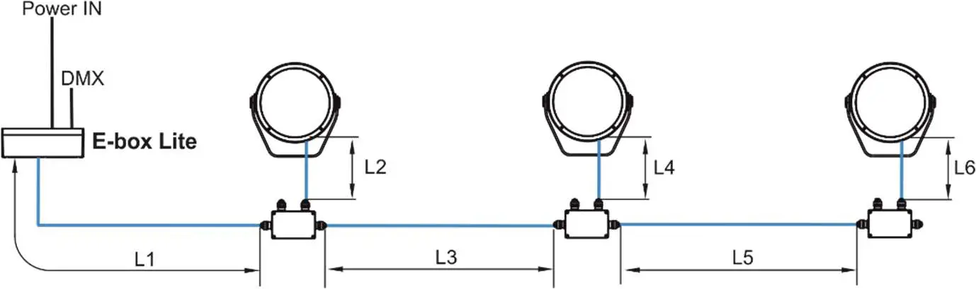
Example: Total cable length=L1+L2+L3+L4+L5+L6
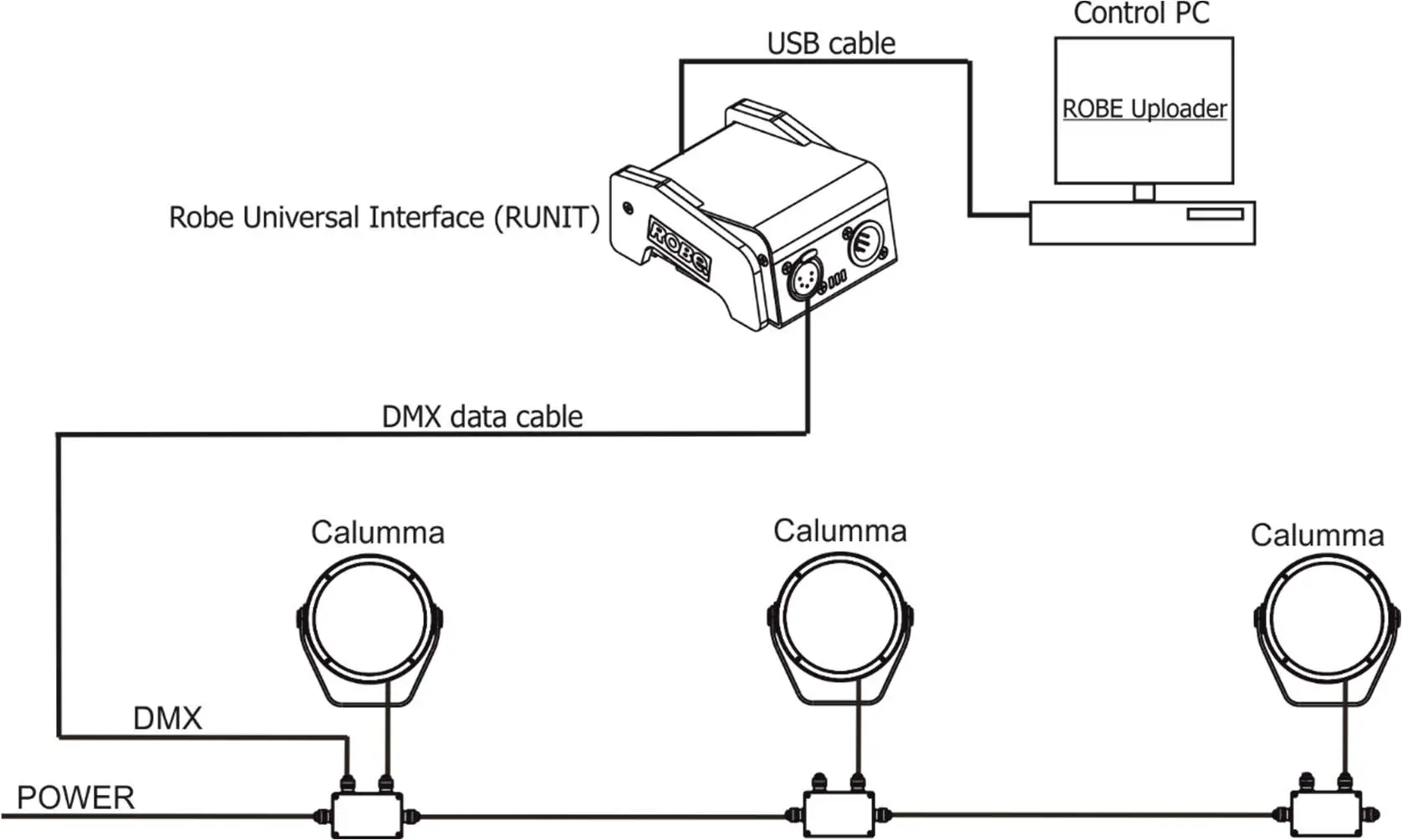
Example with IN/OUT cables
Standard mode is intended for this connection.
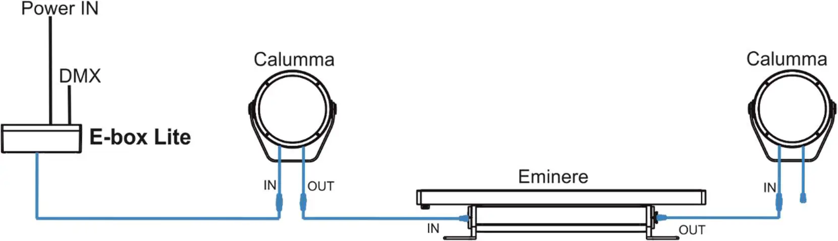
Combination of Calummas and Emineres
Connection of leader cables of the Calumma M
Leader Cable (CE):
| Wire | Power Connection | Wire | Data Connection |
| Brown | Live | Orange | Data – |
| Blue | Neutral | Purple | Data + |
| Yellow/Green | Ground (Earth) | Shielding | Data ground (0V) |
Fixture´s Amphenol connectors are dust and water protected according to IP 67 by mating with related Amphenol connectors. They cannot stay disconnected outdoor.
The output connector at last fixture in the Calumma chain has to always be covered with the water-tight cap to keep declared IP rating.
The Calumma modules with IN/OUT cables should be connected to the E-box which allows power supply of the Calumma modules and their control.
Do not connect (disconnect) Calummas to the E-box or Booster box and each other when they are under voltage!
When you change any setting of the E-box, disconnect the E-box from power and connect it to power again
to activate changes which you have made.
The tables below state max. theoretical number of Calummas connected to the one LED output of the E-box without Booster boxes. The following table applies for the Standard mode of E-boxes.
| Calumma M MC | Voltage | |||
| Cable length * | 120V | 190V | 230V | 277V |
| 10 m | 28 | 44 | 54 | 65 |
| 20 m | 28 | 44 | 54 | 65 |
| 30 m | 20 | 44 | 54 | 65 |
| 50 m | 12 | 30 | 43 | 63 |
| 70 m | 8 | 21 | 31 | 45 |
| 100 m | 6 | 15 | 22 | 32 |
| 200 m | 3 | 7 | 11 | 16 |
| 500 m | 1 | 3 | 4 | 6 |
| Calumma M SC | Voltage | |||
| Cable length * | 120V | 190V | 230V | 277V |
| 10 m | 30 | 48 | 58 | 70 |
| 20 m | 30 | 48 | 58 | 70 |
| 30 m | 21 | 48 | 58 | 70 |
| 50 m | 13 | 32 | 47 | 68 |
| 70 m | 9 | 23 | 34 | 49 |
| 100 m | 6 | 16 | 24 | 34 |
| 200 m | 3 | 8 | 12 | 17 |
| 500 m | 1 | 3 | 5 | 7 |
* Cable length is a total cable length between power supply (e.g. E-box) and last connected Calumma. Example: Total cable length=L1+L2+L3
Notice for the E-box Star: The tables above state max. total number of Calummas connected to 6 LED outputs of the E-box Star (or max. number of Calummas connected to one output if the rest of outputs is not connected).
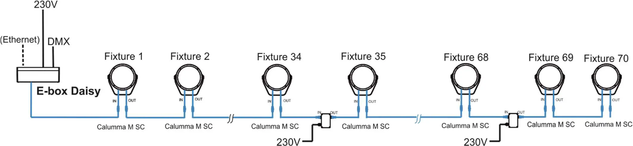
Booster box
To compensate a voltage drop in large installation, the Booster boxes have to be connected in the chain of Calummas (connected IN/OUT method) at every LED output of the E-box.
The following tables give numbers of Calummas after which the Booster box has to be installed in the chain of Calummas (at one LED output of the E-box). The following table applies for the Standard mode of E-boxes.
| Calumma M MC | Max. number of Calummas M MC=191 | |||
| Voltage | ||||
| Cable length | 120V | 190V | 230V | 277V |
| 10 m | 28 | – | – | – |
| 20 m | 28,56 | 44 | 54 | 65 |
| 30 m | 20,40,60,80,100 | 44,88 | 54,108 | 65 |
| 50 m | 12,24,48,56,64,76,88,100.. | 30,60,90,120, 150,180 | 43,86,129,172 | 63,126 |
| 70 m | 8,16,24,32,40,48,56,64,72, 80,88,96…. | 21,42,63,84,105, 126….. | 31,62,93,124,1 55,176… | 45,90,135,1 80,225… |
| 100 m | 6,12,18,24,30,36,42,48,54, 60,66,72,78,84,90,96,102…. | 15,30,45,60,75,9 0,105,120,135… | 22,44,66,88,11 0,132,154… | 32,64,96,12 8,160,192 |
| 200 m | 3,6,9,12,15,18,21,24,27,30, 33,36,39,42,45,48,51,54,57,60,63,66,69,72,75,78,81… | 7,14,21,28,35,42 ,49,56,63,70,77, 84,91,98,105… | 11,22,33,44,55, 66,77,88,99,11 0… | 16,32,48,64, 80,96,112,1 28,144… |
| 500 m | 1,2,3,4,5,6,7,8,9,10,11… | 3,6,9,12,15,18,2 1,24,27,30,33,36 ,39,42,45,48,51, 54,57,60,63,66… | 4,8,12,16,20,24 ,28,3236,40,44, 48,52,56,60,64, 68,72,76,80…. | 6,12,18,24,3 0,36,42,48,5 4,60,66,72,7 8,84,90,96… |
| Calumma M SC | Max. number of Calummas M SC=191 | |||
| Voltage | ||||
| Cable length | 120V | 190V | 230V | 277V |
| 10 m | 30 | – | – | – |
| 20 m | 30,60 | 48 | 58 | 70 |
| 30 m | 21,42,63,84,105…. | 48,96 | 58 | 70 |
| 50 m | 13,26,39,52,65,78,91… | 32,64,96,128,15 8,180… | 47,94,141,188… | 68,136 |
| 70 m | 9,18,27,36,45,54,63…. | 23,46,69,92,115 … | 34,68,102,136… | 49,98,147,1 96.. |
| 100 m | 6,12,18,24,30,36,42,48,54, | 16,32,48,64,80,9 | 24,48,72,96,12 | 34,68,102,1 |
| 60,66,72,78,84,90,96,102…. | 6,112,128,144… | 0… | 36… | |
| 200 m | 3,6,9,12,15,18,21,24,27,30, | 8,16,24,32,40,48 | 12,24,48,56,64, | 17,34,51,68, |
| 33,36,39,42,45,48,51,54,57 | ,56,64,72,80,88, | 76,88,100.. | 85,102 | |
| ,60,63,66,69,72,75,78,81… | 96…. | |||
| 500 m | 1,2,3,4,5,6,7,8,9,10,11…. | 3,6,9,12,15,18,2 | 5,10,15,20,25,3 | 7,14,21,28,3 |
| 1,24,27,30,33,36 | 0,35,40…. | 5,42,49,56,6 | ||
| ,39,42,45,48…. | 3,70,77… |
Example: E-box Daisy, Power supply= 230V, Cable length=70m, fixture=Calumma M SC
The Booster box has to be connected after every 34th Calumma M SC (fixture 34 and fixture 68) from 70 fixtures.
Booster box installation
ALWAYS DISCONNECT THE CALUMMAS FROM MAINS BEFORE CONNECTING/DISCONNECTING THE BOOSTER BOX.
The Booster box falls under protection class I. Therefore, every Booster box has to be connected to a mains socket outlet with a protective earthing connection.
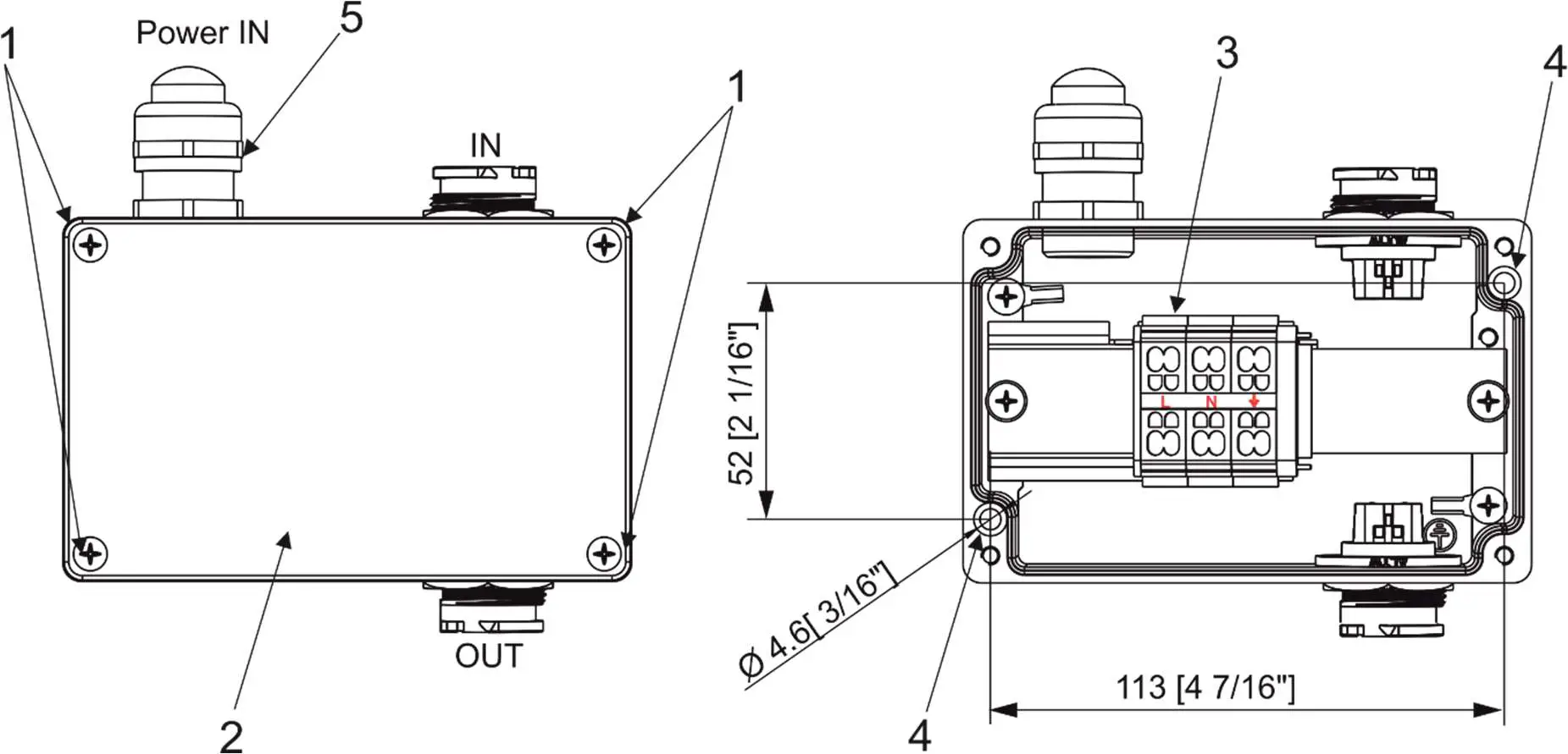
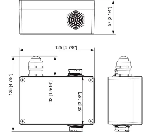
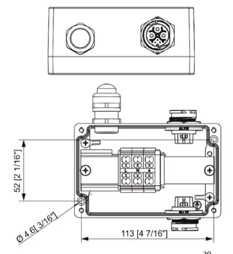
- Unscrew the four screws (1) from the cover (2) on the Booster box to get access to the terminal block (3) and two mounting holes of diameter of 4.6 mm (4).
- Screw the Booster box on a non-flammable flat surface and connect cables.

- Connect power cable.
Remove the end cap from the cable gland before passing the power cable.
The cable gland M20 x 1.5 (5) with a standard seal serves for a cable of diameter of 7-13mm, for smaller diameter of cable (4-8mm) you have to remove the original seal from the cable gland M20 x 1.5 and use the enclosed reducing seal instead of it. The reducing seal for diameter of cable 4-8mm (P/N 13051388) is enclosed in the Booster box.
Power connectionL N (earth) Core (CE) Braun Blue Green/yellow We recommend to apply an adequate layer of the paste LOCTITE 5331 on the plastic holder of the cable gland before inserting it into the body of the gland and an adequate layer of the paste LOCTITE 577 on the thread of the gland body.
Cable gland M20x1.5 - Screw the cover (2) back on the Booster box.
Software update
Software update of Calummas M has to be done by means of the software ROBE Uploader running on PC.
The ROBE Uploader is a software for automatized software update of ROBE fixtures. The ROBE Uploader switches Calummas to the update mode automatically.
Please see https://www.robe.cz/robe-uploader/ for more information.
Note: Calumma M modules in DALI connection and ON/OFF connection cannot be updated.
The software update depends on a method of Calummas M connection.
DMX or Ethernet connection via E-box
If the option Standard is selected from the menu E-box mode, the E-box will be updated including connected Calumma M modules. You have to use the file EminereEbox.lib in the ROBE Uploader for this operating mode. The Standard mode is usually used in IN/OUT connection (without junction boxes).
If the option Pass-Thr is selected from the menu E-box mode, you have to do the following steps to update Calummas M including the E-box. The Pass-Through mode is usually used in connection with junction boxes.
- Update connected LED modules by means of the file Calumma.lib in the ROBE Uploader.
- Set the E-box to the Standard mode and switch it off/on. Use the file EminereEbox.lib in the ROBE Uploader for software update of the E-box.
- After updating the E-box, set the E-box to the Pass-Through mode and switch it off/on.
For more information about updating please see the E-box Lite/Daisy/Star user manual. Examples:
- DMX connection and Robe Universal Interface, IN/OUT connection.

- Ethernet connection, IN/OUT connection.

- By means of DMX connection and Robe Universal Interface, connection via junction boxes.

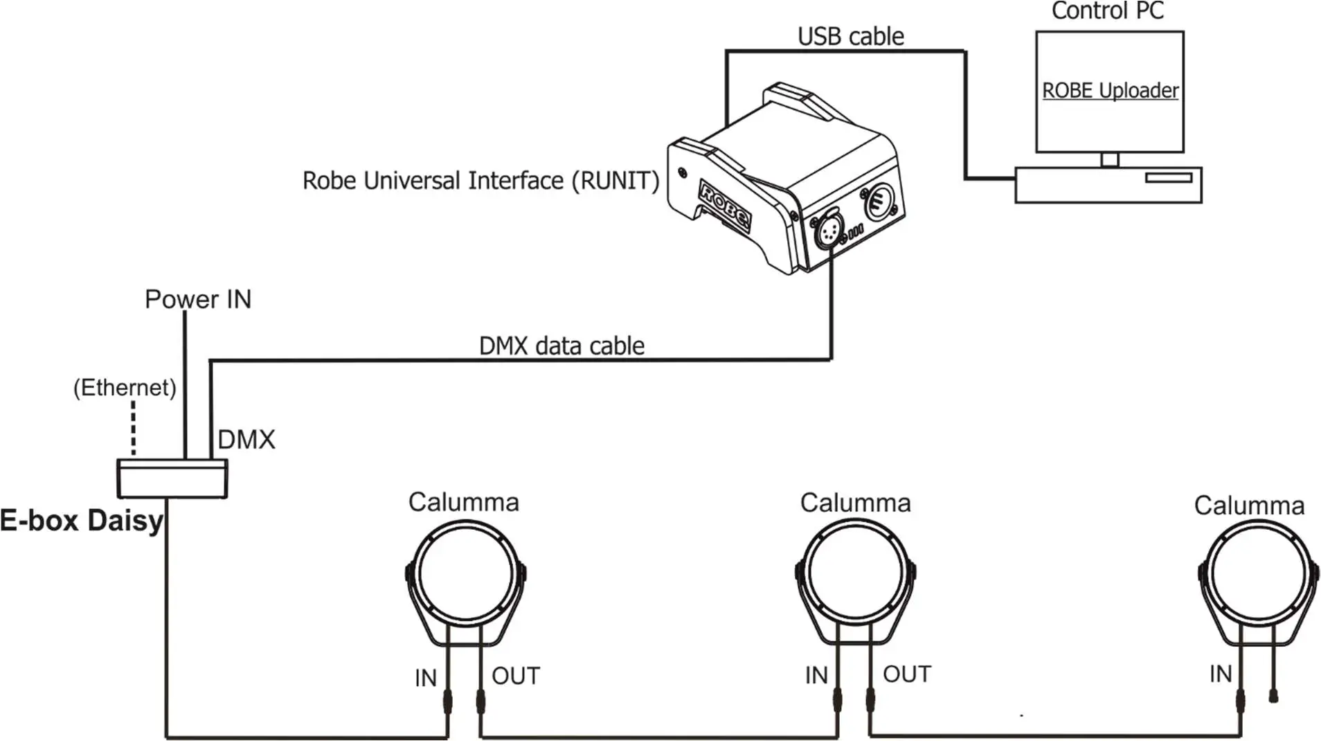
DMX connection
For updating of Calumma modules, use the file Calumma.lib in the ROBE uploader.
Technical specifications
Power supply
- Electronic auto-ranging
- Input voltage: 120 – 277V AC, 50/60 Hz
- Power consumption:
- Calumma M MC: 65 W
- Calumma M SC: 60 W
- Inrush current:
- Calumma M MC: 70A/250us (cold start)
- Calumma M SC: 70A/250us (cold start)
Optic
- Light source:
- Calumma M MC: 7 x high power multichip LEDs
- Calumma M SC: 37 x high power single chip LEDs
- Colour variants: RGBW (W – 6500 K), RGBA, PW (W – 3000 K)
- Beam Angle Calumma M MC:
- Symetrical: 9°, 15°, 25°, 30°, 45°, 65°, 100°
- Bi-symetrical: 10° x 30°, 30° x 10°, 10° x 60°, 60° x 10°, 15° x 45°, 45° x 15°,
- 15°x90°, 90°x15°, 30°x60°, 60°x30°, 30°x90°, 90°x30°
- Beam Angle Calumma M SC:
- Symetrical: 10°, 15°, 25°, 30°, 45°, 65°, 100°
- Bi-symetrical: 10° x 30°, 30° x 10°, 10° x 60°, 60° x 10°, 15° x 45°, 45° x 15°,
- 15°x90°, 90°x15°, 30°x60°, 60°x30°, 30°x90°, 90°x30°
- Asymmetrical side, Asymmetrical forward
- Projected Lumen Maintenance: L90B10 >90.000 hrs, Ta = 25°C / 77°F
Compatible drivers
- E-box Daisy
- 1 Output
- 1 Main power Input
- Control: DMX, Art-Net, sACN , W-DMX control, RDM
- Pixel control
- 120-277V Input
- Connection via terminal blocks, inlets via grommet
- IP67
- E-box Star
- 6 outputs
- 1 Main power Input
- Control: DMX, Art-Net, sACN , W-DMX control, RDM
- Pixel control
- 120-277V Input
- Connection via terminal blocks, inlets via grommet
- IP67
- E-box Lite
- 1 output
- 1 Main power Input
- Control: DMX, W-DMX control, RDM
- Pixel control
- 120-277V Input
- Connection via screw terminal blocks, inlets via grommet
- IP67
Mounting method
- Via yoke
- Adjustability: -180°/+180°
Housing
- High pressure die-cast aluminium body
- Tempered glass
Cooling system
- Convection
Total heat dissipation
- Calumma M MC: 166 BTU/h (calculated)
- Calumma M SC: 153 BTU/h (calculated)
Protection factor
- CE: IP 67 (IP 66 junction box)
- US: Suitable for wet location
Impact rating
- IK10
Operating ambient temperature range
- -20°C /+40°C (-4°F /+104°F)
Operating temperature
- +67°C @ Ambient +40°C (+153°F @ Ambient +104°F)
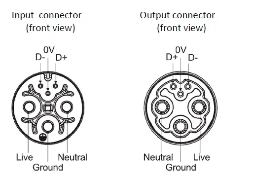
Connection – CE
- DMX connection
- Calumma IN: Flamar 3x AWG 16 + 1 x (2x AWG 24), Standard 1m with bare-end (P/N 1305 1508)
- Interconnecting cables: Flamar 3x AWG 16 + 1 x (2x AWG 24) (P/N 1305 1508)
- Junction box (P/N 1098 0714)
- Wireless DMX connection
- Calumma IN: Flamar 3x AWG 16 + 1 x (2x AWG 24), Standard 1m with bare-end (P/N 1305 1508)
- Junction box (P/N 1098 0714)
- Wireless to DMX connection
- Calumma IN: Flamar 3x AWG 16 + 1 x (2x AWG 24), Standard 1m with bare-end (P/N 1305 1508)
- Interconnecting cables: Flamar 3x AWG 16 + 1 x (2x AWG 24) (P/N 1305 1508)
- Junction box (P/N 1098 0714)
- DALI connection
- Calumma IN: SJTW 5x 14AWG, standard 1m with bare-end (P/N 1305 3336)
- Interconnecting cables: SJTW 5x 14AWG (P/N 1305 3336)
- Junction box (P/N 1098 0714)
- DMX or Ethernet via E-box and Junction box
- Calumma IN: Flamar 3x AWG 16 + 1x (2x AWG 24), standard 1m with bare-end (P/N 1305 1508)
- Interconnecting cables: Flamar 3x AWG 16 + 1 x (2x AWG 24), (P/N 1305 1508)
- Junction box (P/N 1098 0714)
- DMX or Ethernet via E-box and IN/OUT cables
- Calumma IN: Leader cable MM (P/N 13053493) with hybrid connector, standard 0.5 m
- Calumma OUT: Leader cable MF (P/N 13053494) with hybrid connector, standard 0.5 m
- Leader cables: Leader Cable FF 2 m (P/N 13053438)
- Leader Cable FF 5 m (P/N 13053440)
- Leader Cable FF 10 m (P/N 13053436)
- Leader Cable FF 25 m (P/N 13053437)
- Jumper cables: Jumper Cable FF/FM 0,25 m (P/N1 3053422)
- Jumper Cable FF/FM 0,5 m (P/N 13053423)
- Jumper Cable FF/FM 1 m (P/N 13053425)
- Jumper Cable FF/FM 2 m (P/N 13053427)
- Jumper Cable FF/FM 3 m (P/N 13053428)
- Jumper Cable FF/FM 5 m (P/N 13053430)
- Jumper Cable FF/FM 10 m (P/N 13053424)
- Connection – US
- Wireless DMX connection
- Calumma IN: SJTW 6x 14AWG, standard 1m with bare-end, (P/N 1305 3480)
- Junction box (P/N 1098 0714)
- Wireless to DMX connection
- Calumma IN: SJTW 6x 14AWG, standard 1m with bare-end, (P/N 1305 3480)
- Interconnecting cables: SJTW 6x 14AWG (P/N 1305 3480)
- Junction box (P/N 1098 0714)
- DALI connection
- Calumma IN: SJTW 5x 14AWG, standard 1m with bare-end (P/N 1305 3336)
- Interconnecting cables: SJTW 5x 14AWG (P/N 1305 3336)
- Junction box (P/N 1098 0714)
- DMX or Ethernet via E-box and Junction box
- Calumma IN: SJTW 6x 14AWG ,standard 1m with bare-end (P/N 1305 3480)
- Interconnecting cables: SJTW 6x 14AWG ,(P/N 1305 3480)
- Junction box (P/N 1098 0714)
Weight
- Calumma M SC: 5.9 kg (13 lbs)
- Calumma M MC: 5.77 kg (12.77 lbs)
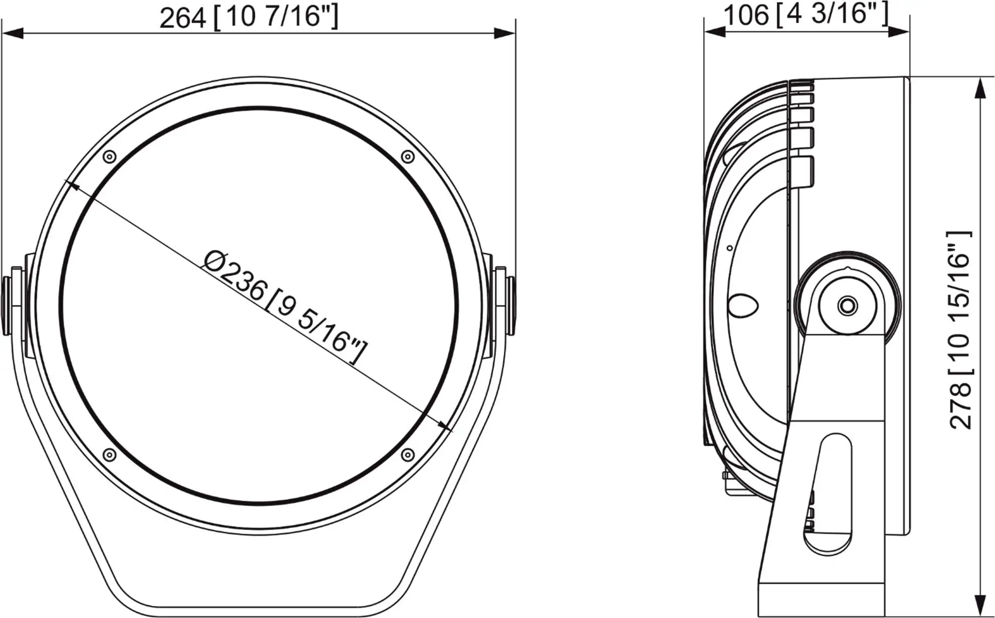
Dimensions (All dimensions in mm [inch])
Junction box
Booster box
Included items
- 1 x Calumma M MC / Calumma M SC
- 1 x User manual
Optional accessories
Junction Box for Calumma, 1x Output, Ral 9006 (P/N 10980757)
Junction Box for Calumma, 1x Output, Ral 9011 (P/N 10980714)
Top Hat Calumma M RAL9011 (P/N 10980734)
Half Top Hat Calumma M RAL9011 (P/N 10980723)
Tenon Adaptor for Calumma M
Pole Mount Bracket for Calumma M
E-box Daisy (P/N 10063655)
E-box Daisy/W (P/N 10063638)
E-box Lite (P/N 10063657)
E-box Lite/W (P/N 10063653)
E-box Star (P/N 10063656)
E-box Star/W (P/N 10063644)
Booster box (P/N 10063712)
Cleaning and maintenance
DANGER !
Disconnect from the mains before starting any maintenance or cleaning work
Rinse off loose dirt with low pressure water spray. Wash the housing with a soft brush or sponge and a mild, non-abrasive washing detergent. Rinse it.
Maintenance and service operations are only to be carried out by a qualified person.
Should you need any spare parts, please use ROBE OEM parts.
Disposing of the product
To preserve the environment please dispose or recycle this product at the end of its life according to the local regulations and codes.
ChangeLog
This section summarizes changes in the user manual.
| Version of manual | Date of issue | Description of changes |
| 1.1 | 12/10/2022 | DMX chart ver.1.1 |
| 1.2 | 05/01/2023 | Software update description changed |
Specifications are subject to change without notice.
January 5, 2023
Copyright © 2022-2023 Robe Lighting – All rights reserved
Made in CZECH REPUBLIC by ROBE LIGHTING s.r.o. Palackeho 416/20 CZ 75701 Valasske Mezirici
| DMX protocol for Calumma – All sizes – RGBW(A) | ||||||||
| Version: 1.1 (16 modes in total) | ||||||||
| Mode/Channels in all | Mode 1- RGBW(A)-8bit, Mode 2- RGB 8-bit, Mode 3- full RGBW(A) | |||||||
| 1 | 2 | 3 | 4 | 5 | 6 | 7-10 | Mode 4- White-full control, Mode 5- Reduced RGBW(A) | |
| 4 | 3 | 12 | 3 | 6 | 8 | Reserved | Mode 6- Reduced RGBW(A)+white control | |
| RGBW/RGBA/RGB modes | ||||||||
| Mode/channels | DMX Value | Function | Type of control | |||||
| 1 | 2 | 3 | 4 | 5 | 6 | |||
| 1 | 1 | 1 | – | 1 | 1 | Red | ||
| 0 – 255 | Red LEDs saturation control (0-100%) | proportional | ||||||
| – | – | 2 | – | – | – | Red Fine | ||
| 0 – 255 | Red LEDs saturation control fine | proportional | ||||||
| 2 | 2 | 3 | – | 2 | 2 | Green | ||
| 0 – 255 | Green LEDs saturation control (0-100%) | proportional | ||||||
| – | – | 4 | – | – | – | Green Fine | ||
| 0 – 255 | Green LEDs saturation control fine | proportional | ||||||
| 3 | 3 | 5 | – | 3 | 3 | Blue | ||
| 0 – 255 | Blue LEDs saturation control (0-100%) | proportional | ||||||
| – | – | 6 | – | – | – | Blue Fine | ||
| 0 – 255 | Blue LEDs saturation control fine | proportional | ||||||
| 4 | – | 7 | – | 4 | 4 | White (Amber) | ||
| 0 – 255 | White LEDs saturation control (0-100%) | proportional | ||||||
| – | – | 8 | – | – | – | White (Amber) Fine | ||
| 0 – 255 | White LEDs saturation control fine | proportional | ||||||
| – | – | 9 | 1 | – | 5 | Green correction | ||
| 0 | Uncorrected white | step | ||||||
| 1-127 | Minus green – uncorrected white | proportional | ||||||
| 128 | Uncorrected white (128=default) | step | ||||||
| 129-255 | Uncorrected white – Plus green | proportional | ||||||
| – | – | 10 | 2 | – | 6 | Colour temperature correction (CTC) | ||
| 0 | No function (0 – default) | step | ||||||
| 1 – 10 | Tungsten dimming 2700 K | step | ||||||
| 11 – 20 | Tungsten dimming 3200 K | step | ||||||
| 21-255 | Colour temperature changing from 1800 K –> 6500 K | proportional | ||||||
| (21-1800K, 66-2700K, 91-3200K,141-4200K, 211-5600K, 255- 6500K) | ||||||||
| – | – | 11 | 3 | 5 | 7 | Dimmer | ||
| 0 – 255 | Light intensity coarse (0-100%) | proportional | ||||||
| – | – | 12 | – | 6 | 8 | Dimmer Fine | ||
| 0 – 255 | Light intensity fine | proportional | ||||||
| Copyright © 2022 Robe Lighting s.r.o. – All rights reserved | ||||||||
| All Specifications subject to change without notice | ||||||||
| DMX protocol for Calumma – All sizes – MC and SC | |||||
| Version: 1.1 (16 modes in total) | |||||
| Mode/Channels in all | TW Modes: Mode 6- White selection + Dimmer, Mode 7- WW + CW | ||||
| 11 | 12 | 13 | 14-16 | PW Mode: Mode 8- Dimmer | |
| 3 | 4 | 2 | Reserved | ||
| TW and PW modes | |||||
| Mode/channels | DMX Value | Function | Type of control | ||
| 6 | 7 | 8 | |||
| 1 | – | – | White colour selection | ||
| 0 – 255 | White from 2700 K – 6500 K | proportional | |||
| – | 1 | – | Warm White | ||
| 0 – 255 | Warm White LEDs saturation control (0-100%) | proportional | |||
| – | 2 | – | Cool White | ||
| 0 – 255 | Cool White LEDs saturation control (0-100%) | proportional | |||
| 2 | 3 | 1 | Dimmer | ||
| 0 – 255 | Light intensity coarse (0 – 100%) | proportional | |||
| 3 | 4 | 2 | Dimmer Fine | ||
| 0 – 255 | Light intensity fine | proportional | |||
| Copyright © 2022 Robe Lighting s.r.o. – All rights reserved | |||||
| All Specifications subject to change without notice | |||||


