![]() Roth Mini shunt Plus
Roth Mini shunt Plus
Installation
 Living full of energy
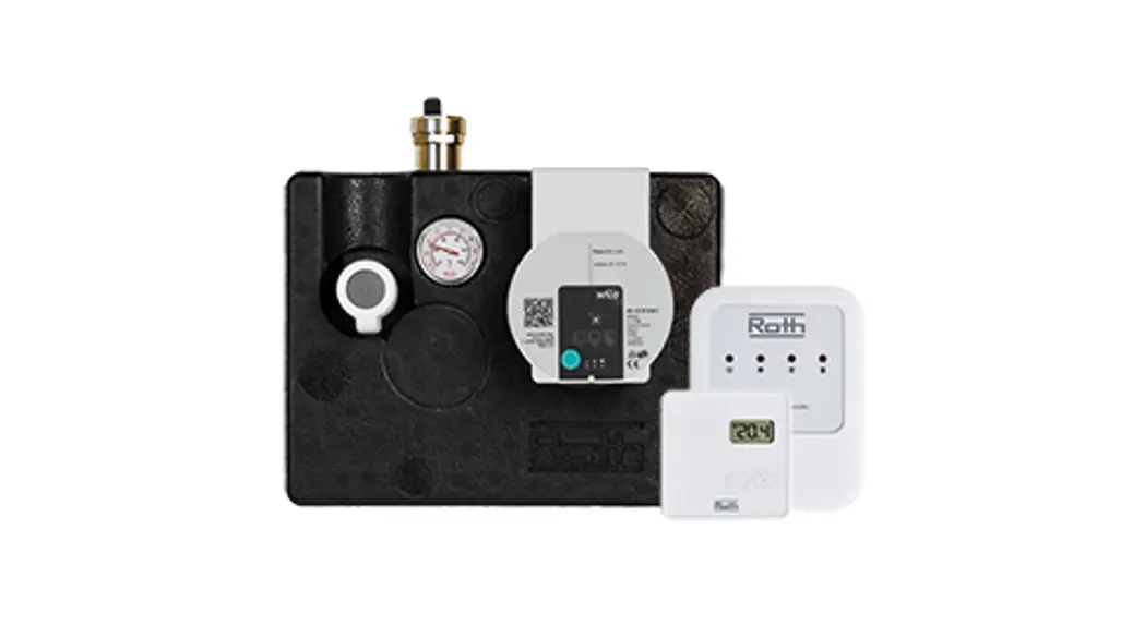
Description
Roth Mini shunt Plus is intended for supplying and connecting small floor heating system to existing radiator heating systems. Two underfloor hes ting circuits can be connected with the dual coupling. The room tempera- ture is controlled via a thermostat with capillary sensor or a wireless room thermostat and actuator (fixed-value temperature contra) Can be used on both 1- and 2-string systems and has a built-in temperature limit of 45°C.
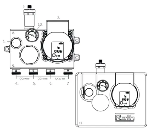
Roth Mini shunt Plus:
| 1. Valve for thermostat or actuator | 7. Flow, secondary |
| 2. Circulation pump | 8. Regulation valve for water volume |
| 3. Air vent | 9. Bypass valve for 1- or 2-string systems |
| 4. Flow, primary | 10. Analog thermometer |
| 5. Return, primary | 11 Insulation Box |
| 6. Return, secondary |
| Pipe dimensions | Number of loops | May. pipe length |
| 10,5 mm | 1 | 70m |
| 10,5 mm | 2 | 2x70m |
| 16 mm | 1 | 90m |
| 16 mm | 2 | 2x90m |
| 20 mm | 1 | 120m |
| 20 mm | 2 | 2x120m |
Secure an equal length when installing 2 loops.
Assembly requirements
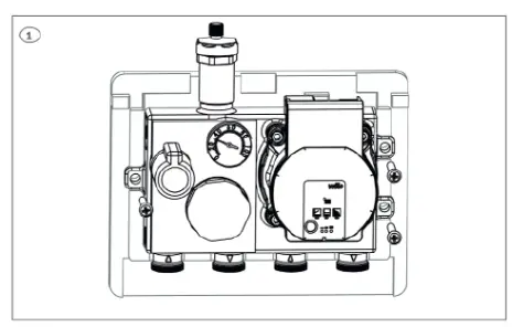
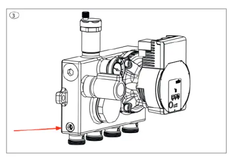
- The Roth Mini shunt Plus must be mounted in horizontal position as shown in picture 1
- It must be ensured there is a differential pressure of Min. 15 kPa and Max. 50 kPa
- The water temperature on the installation side should be min. 15°C higher than the underfloor circuit.
- Always flush the installation before attaching the Roth Mini shunt Plus.
Assembly
- Attach the Mini shunt Plus to a suitable wall. The pump will not cause noise due to the dense shunt body.
- Vent and perform pressure testing according to industry rules. Water filing, flushing and venting is optimized by combining the design of the shunt body with the air vent.
- Set between 1- and 2-string systems see page 6.
- Mount the thermostat or the actuator (wireless control only) on the valve
- Sensor or thermostat is placed approx. 1.7 m above the floor on an inner wall in a representative place.
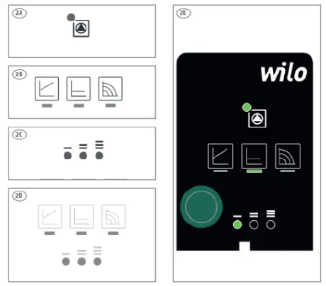
- Set the pump to constant pressure. Normally. a setting as shown in image 2€ will be sufficient to achieve optimal comfort with minimum noise.
Indicator lights (LEDs)
(2A)
> Signal display
> LED is lit up in green in normal operation
> LED lights up/flashes in case of a fault
(2B)
> Display of selected control mode AP-v, AP-c and constant speed
(2C)
> Display of selected pump curve ( I, I I, I I) within the control mode
(2D)
> LED indicator combinations during the pump venting function, manual restart and key lock
>No light in LED = No power
Setting of Mini shunt for 1- or 2-string system, picture 3+ 4
(The factory setting is 2-string)
- 2-string system 2.5 mm Allen screw must be completely at the bottom, see picture 3.
- L-string system, 2.5 mm Allen screw must be set in relation to the desired bypass water volume. Figure 4 shows the percentage of water that is passed through the bypass screw at the various settings.
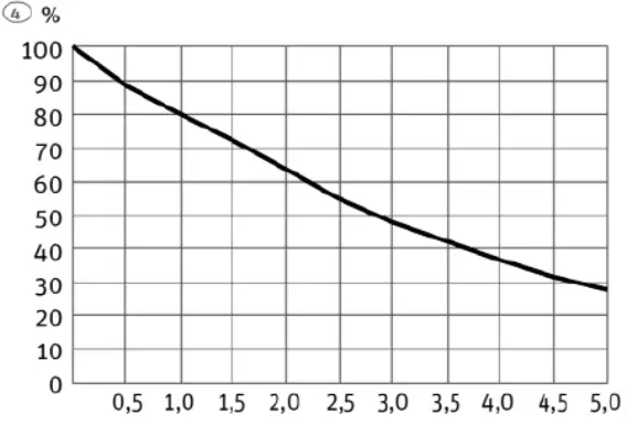 Bypass valve, turns open
Technical data
| Application | Underfloor heating system |
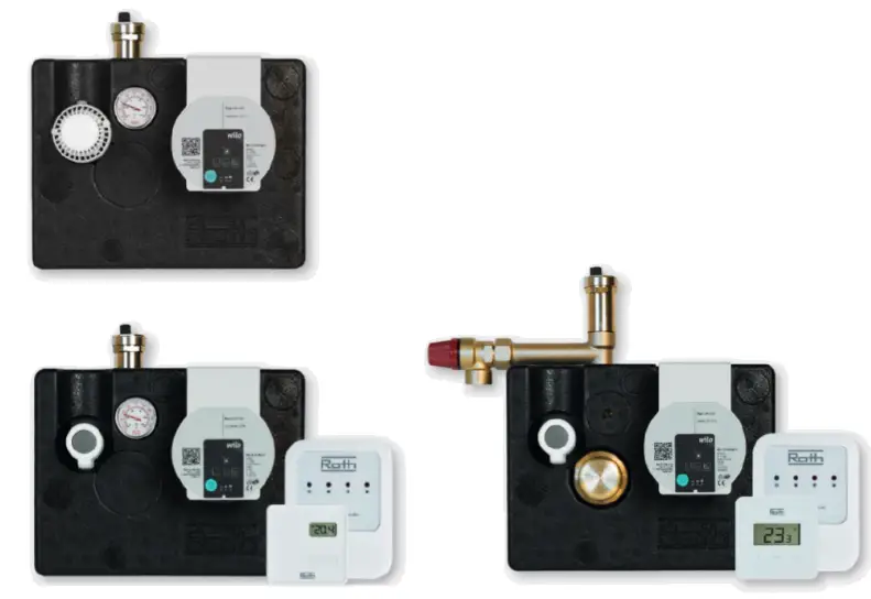
| Roth Mini shunt Plus with capillary sensor | HVAC no. 7466210141 |
| Roth Mini shunt Plus with basic wireless thermostat | HVAC no. 7466210310 |
| Roth Minishunt Plus with advanced wireless thermostat and heating element | HVAC no. 7466210351 |
| Max operating pressure | 6 bar |
| Max operating temperature | Max. 80°C on primary side |
| Max operating temperature | Max. 45°C on secondary side |
| Pump | Wilo PARA MS/ 6-43/ SC-12 |
| Thread primary side | EURO 4″ EXL/MT |
| Thread secondary side | ELIXIR 34″ Ext./MT |
| Material | Brass CW614 |
| Electrical connection | 230V, 50 Hz with earthing |
| Pump output | 3-45W |
| Antifreeze | Water mixed with max. 50%Glycol |
Accessories
| Roth Duo CC T Connection – 10,5 mm | HVAC no. 7401974830 |
| Roth Duo Splitter Set 4″ 12 – 20 mm | HVAC no. 7046296220 |
| Roth adapter 16 mm x 34″ EURO | HVAC no. 7046217546 |
| Roth adapter 20 mm x34* EURO | HVAC no. 7046217550 |
| Roth marigold coupler 10.5 mm x 3% EURO | HVAC no. 7401974810 |
| Roth marigold coupler 12 mm x %” EURO | HVAC no. 7401974812 |
| Roth marigold coupler 15 mm x %4 EURD | HVAC no. 7401974815 |
| Roth marigold coupler 16 mm x 4 EURD | HVAC no. 7401974816* |
| Roth marigold coupler 17 mm x %4 EURO | HVAC no. 7401974817 |
| Roth marigold coupler 18 mm x %” EURO | HVAC no. 7401974818 |
| Roth marigold coupler 20 mm x %” EURO | HVAC no. 7401974820* |
| Roth marigold cabinet Roth Mini shunt Plus | HVAC no. 7046219540 |
 Roth Mini shunt Plus QR
https://roth.support/minishunt
![]()
| ROTH DANMARK A/S Centervej 5 3600 Frederikssund Tl +45 4738 0121 E-mail: servicemroth-danmark.dk roth-danmark.dk | ROTH SVERIGE AB Hujdrodergatan 22 212 39 Malmo Tel. +46 40534090 Fax +46 40534099 E-mail: [email protected] roth-sverige.se | ROTH NORGE AS Billingstadsletta 19 1396 Billingstad Tel. +47 67 57 54 00 E-mall: [email protected] facebook.com/RothNorge | ROTH FINLAND OY Sysimiehenkatu 12 10300 Karjaa Puh. +358 (0)19 440 330 S-posti: [email protected] facebook.com/RothFinland |
ROTH UK Ltd
1a Berkeley Business Park
Wainwright Road
Worcester
WR4 9FA
Phone +44 (0) 1905 453424
E-Mail [email protected]
[email protected]
[email protected]
[email protected]
roth-uk.com


