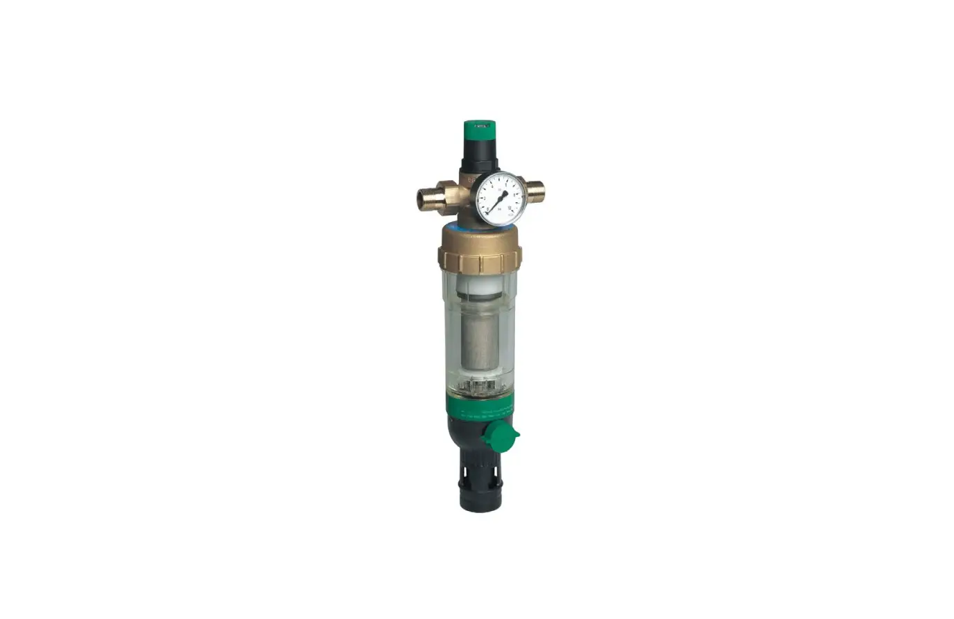
resideo FK09S Braukmann Filter Combination Installation Guide
Safety Guidelines
- Follow the installation instructions.
- Use the appliance
- according to its intended use
- in good condition
- with due regard to safety and risk of danger.
- Note that the appliance is exclusively for use in the applications detailed in these installation instructions (see 2 Technical Data). Any other use will not be considered to comply with requirements and would invalidate the warranty.
- Please take note that any assembly, commissioning, servicing and adjustment work may only be carried out by authorized persons.
- Immediately rectify any malfunctions which may influence safety
Technical Data
| Media | |
| Medium: | Drinking water |
| Connections/Sizes | |
| Connection sizes: | 1/2″ – 2″ |
| Pressure values | |
| Min. operating pressure: | 1.5 bar (dynamic pressure) |
| Max. inlet pressure with clear filter bowl: | 16 bar |
| Outlet pressure: | 1.5 – 6 bar |
| Operating temperatures | |
| Max. operating temperature medium accord. to EN 1567: | 30 °C |
| Specifications | |
| Installation position: | Horizontal with filter bowl downwards |
Options
For Options visit homecomfort.resideo.com/europe
Assembly
Installation Guidelines
Install in horizontal pipework with filter bowl downwards
- This position ensures optimum filter efficiency
- Install shut-off valves
- Ensure good access
- Pressure gauge can be read off easily
- Degree of contamination can be easily seen with clear filter bowl
- Simplifies maintenance and inspection
- The installation location should be protected against frost
- Related to the EN 806-2 it is recommended to install the filter immediately after the water meter
- In order to avoid flooding, it is recommended to arrange a permanent, professionally dimensioned wastewater connection
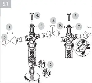
Assembly instructions
- Thoroughly flush pipework
- Fit filter combination
- Note flow direction
- Install without tension or bending stresses
- Seal in pressure gauges
- Set outlet pressure
Discharge of reverse rinsing water
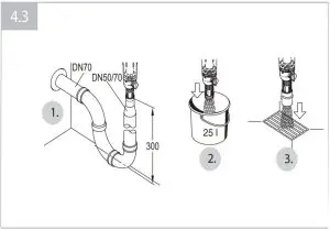
The reverse rinsing water must be routed to the drain channel in such a way that no backwater can occur. To do this there are 3 options:
- Direct connection:
- Connector DN 50/70 as well as the necessary pipes and siphon (3 elbows 90°) in DN 70.
- Discharge into floor drain
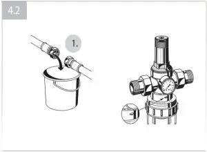
- Drain into open container.
Filter size: Reverse rinsing volume*
1/2″ and 3/4″:12 Liter
1″ and 1 1/4″: 15 Liter
1 1/2″ and 2″ : 18 litres
at 4 bar inlet pressure and 3 x 3 seconds reverse rinsing duration
Start-up
Setting outlet pressure
Set outlet pressure min. 1 bar under inlet pressure.
- Close shut-off valve on inlet
- Release pressure on outlet side (e.g. through water tap)
- Close shut-off valve on outlet
- Loosen slotted screw
- Do not remove slotted screw
- Slacken tension in compression spring
- Turn adjustment handle counter clockwise (-) until it does not move any more
- Slowly open shut-off valve on inlet
- Turn control handle until the setting scale shows the desired value
- Retighten slotted screw
- Slowly open shut-off valve on outlet
Reverse rinsing
During reverse rinsing, an inlet (dynamic) pressure of at least 1.5 bar is required. The reverse rinsing interval depends on the degree of dirt in the water. At the latest every 6 months, reverse rinsing should be carried out according to EN 806-5. Our recommendation at least every 2 months! To ensure convenient and regular adherence to the reverse rinsing interval, we recommend installing an automated reverse rinsing system Z11S.
Filtered water can also be tapped during reverse rinsing.
Manual reverse rinsing
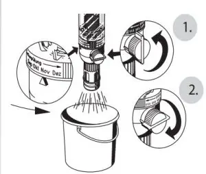
If reverse rinsing water is not to be discharged via a direct connection, a collecting container must be positioned beneath before reverse rinsing.
- Open ball valve by turning the reverse rinsing button to the stop point
- Select bar must be upright
- The patented reverse rinsing system starts
- Close ball valve again after approx. 3 seconds.
Repeat procedure three times- If the filter is extremely dirty, the procedure may have to be repeated additional time
With aid of the memory ring, the next deadline for manual reverse rinsing can be booked.
- If the filter is extremely dirty, the procedure may have to be repeated additional time
Automatic reverse rinsing with the Z11S
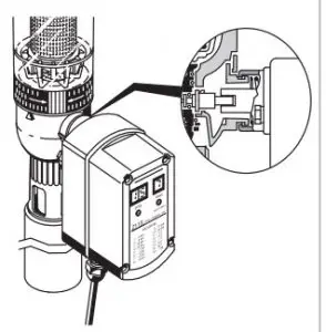
The automated reverse rinsing system Z11S is available as an accessory. The automated system reliably takes over reverse rinsing of the filter at intervals which can be set between 4 minutes and 3 months.
Maintenance
In order to comply with EN 806-5, water fixtures must be inspected and serviced on an annual basis. As all maintenance work must be carried out by an installation company, it is recommended that a servicing contract should be taken out.
In accordance with EN 806-5, the following measures must be taken:
Inspection
Pressure reducing valve
- Close shut-off valve on outlet
- Check outlet pressure using a pressure meter when there is zero through-flow
- If the pressure is increasing slowly, the valve may be dirty or defective. In this instance, carry out servicing and cleaning (See 6.2 Maintenance)
- Slowly open shut-off valve on outlet
Filter
- The filter must be cleaned by reverse rinsing regularly, at least every 6 months. (acc. to EN 806-5) Our recommendation at least every 2 months!
- Non-compliance can lead to the filter becoming blocked This results in a drop in pressure and decreased water flow
- The filter meshes are made of stainless steel. A red coating as a consequence of rust from the pipelines has no influence on function or the way the filter works
CAUTION! Do not forget to do a visual check of the ball valve. Replace if it is dripping!
Maintenance
If necessary, the outside surface of the filter combination can be cleaned. Use only cold, clear drinking water to clean the surfaces! Any other cleansers cause damage to the plastic components!
Pressure reducing valve
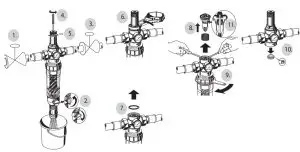
- Close shut-off valve on inlet
- Release pressure on outlet side (e.g. through water tap)
- Close shut-off valve on outlet
- Loosen slotted screw
- Do not remove slotted screw
CAUTION
There is a spring in the spring bonnet. It may cause injuries if the spring is derailing. - Make sure tension in compression spring is slackened!
- Do not remove slotted screw
- Slacken tension in compression spring
- Turn adjustment handle counter clockwise (-) until it does not move any more
- Do not turn in too far!
- Unscrew spring bonnet
- Use double ring wrench ZR10K
- Remove slip ring
- Remove valve insert with a pair of pliers
- Unscrew filter bowl and guide piece
- Use double ring wrench ZR10K
- Remove old filter insert and replace by a new one!
- Remove slotted ring
- Place O-ring onto filter bowl
- Screw in filter bowl hand-tight (without tools)
- Check that sealing ring, edge of nozzle and slotted ring are in good condition, and if necessary replace the entire valve insert
- Reassemble in reverse order
Press in diaphragm with finger before inserting slip ring Screw in filter bowl hand-tight (without tools) - Set outlet pressure and adjust setting scale
- Slowly open shut-off valve on inlet
- Slowly open shut-off valve on outlet.
Filter
- Non-compliance can lead to the filter becoming blocked This results in a drop in pressure and decreased water flow
- The filter meshes are made of stainless steel. A red coating as a consequence of rust from the pipelines has no influence on function or the way the filter works
CAUTION! Do not forget to do a visual check of the ball valve. Replace if it is dripping!
Adjusting the setting scale
f the adjustment knob is removed, this setting is lost. A new setting can be achieved using a pressure gauge.
- Close shut-off valve on inlet
- Release pressure on outlet side (e.g. through water tap)
- Close shut-off valve on outlet
- Loosen slotted screw
- Do not remove slotted screw
- Slowly open shut-off valve on inlet
- Set desired outlet pressure (e.g. 4 bar)
- Align scale (e.g. 4) in middle of viewing window
- Retighten slotted screw
- Slowly open shut-off valve on outlet
Disposal
Observe the local requirements regarding correct waste recycling/disposal!
Troubleshooting
| Problem | Cause | Remedy |
| Water is escaping from the spring bonnet | Diaphragm in valve insert is faulty | Replace valve insert |
| Too little or no water pressure | Shut-off valves up- or downstream of the pressure reducing valve are not fully open | Open the shut-off valves fully |
| Pressure reducing valve is not set to the desired outlet pressure | Set outlet pressure | |
| Filter mesh dirty | Reverse rinsing | |
| Not fitted in flow direction | Fit filter in flow direction (note direction of arrow on housing) | |
| The outlet pressure set does not remain constant | Filter mesh dirty | Reverse rinsing |
| Valve insert, sealing ring or edge of nozzle is contaminated or worn | Replace valve insert | |
| Rising pressure on outlet (e.g. in boiler) | Check check valve, safety group etc |
Spare Parts
For Spare Parts visit homecomfort.resideo.com/europe
Accessories
For Accessories visit homecomfort.resideo.com/europe


