Avenview Hdm-Splitpro-4A Hdmi Quad Multiviewer
GETTING STARTED
IMPORTANT SAFEGUARDS
- Any product, on which the serial number has been defaced, modified or removed.
- Damage, deterioration or malfunction resulting from:
- Accident, misuse, neglect, fire, water, lightning, or other acts of nature, unauthorized product modification, or failure to follow instructions supplied with the product.
- Repair or attempted repair by anyone not authorized by us.
- Any damage of the product due to shipment.
- Removal or installation of the product.
- Causes external to the product, such as electric power fluctuation or failure.
- Use of supplies or parts not meeting our specifications.
- Normal wear and tear.
- Any other causes which does not relate to a product defect.
- Removal, installation, and set-up service charges
Safety Instructions
- Do not dismantle the housing or modify the module.
- Dismantling the housing or modifying the module may result in electrical shock or burn.
- Refer all servicing to qualified service personnel.
- Do not attempt to service this product yourself as opening or removing housing may expose you to dangerous voltage or other hazards
- Keep the module away from liquids.
- Spillage into the housing may result in fire, electrical shock, or equipment damage. If an object or liquid falls or spills on to the housing, unplug the module immediately.
- Have the module checked by a qualified service engineer before using it again.
- Do not use liquid or aerosol cleaners to clean this unit. Always unplug the power to the device before cleaning.
Introduction
The Avenview SW-HDM3D-C6-4x4E, HDMI Matrix with IR, Full 3D Support and now Ethernet over Single CAT6 provides the most flexible and cost effective solution in the market to route high definition video sources plus multi-channel (up to 7.1 channel) digital audio from any of the eight HDMI sources to the remote displays at the same time. Through low cost Cat-5/5e/6 LAN cables, not only high quality video and audio can be transmitted to the display sites, but also users can switch among eight HDMI sources using the push-in button or remote control. With single power design at the source site, each remote module is easily installed without power supply. Furthermore, the built-in IR extension function, users can control the HDMI source devices such as Blu-ray Disc Player, Satellite Receivers etc. at display site directly.
- Supports HDMI Deep Color & Full 3D
- HDCP compliant
- Allows any source to be displayed on multiple displays at the same time
- Allows any HDMI display to view any HDMI source at any time
- Supports 7.1 channel digital audio
- Supports default HDMI EDID and learns the EDID of displays
- The matrix master can switch every output channels to any HDMI inputs by push-in button, IR remote control, or RS-232 control
- Allows controlling local HDMI sources such as DVD and TiVo by attached IR extender from remote receiver to matrix master
- Allows to control matrix master through IR remote control at remote receiver’s site
- Extends video signal up to 35m (115 feet) over CAT5e at 1080p and likely longer with better HDMI source device, better grade HDMI display, and better quality solid CAT6 cable
- Easy installation with rack-mounting and wall-mounting designs for master and receiver respectively
- Fast response time – 2~5 seconds for channel
- Ethernet Control
Package Contents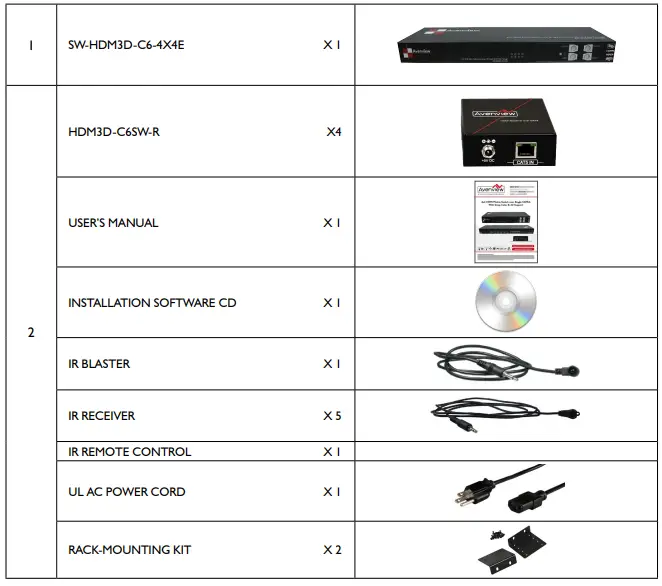
Before Installation
- Put the product in an even and stable location. If the product falls down or drops, it may cause an injury or malfunction.
- Don’t place the product in too high temperature (over 50°C), too low temperature (under 0°C) or high humidity.
- Use the DC power adapter with correct specifications. If an inappropriate power supply is used then it may cause a fire.
- Do not twist or pull by force ends of the UTP cable. It can cause malfunction.
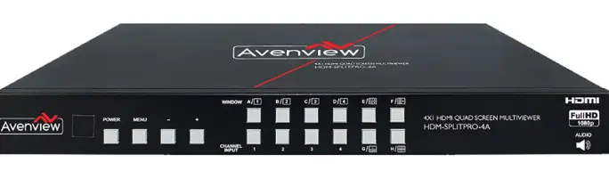
Panel Description
SW-HDM3D-C6-4X4E Front Panel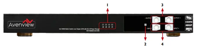
- SOURCE STATUS : Input source indicator LED
- IR SENSOR: IR sensor for receiving the IR commands from IR remote
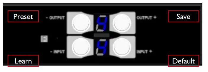
- OUTPUT PUSH BUTTON & 7-SEGMENT LED: Front panel push buttons used to select the number of display channel & LED display for output ports
- INPUT PUSH BUTTON & 7-SEGMENT LED: Front panel push buttons used to select the number of input source & LED display for input channels
SW-HDM3D-C5-4x4E Rear Panel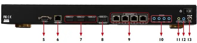
- RS-232: RS-232 control port
- ETHERNET: Ethernet control port
- INPUT 1-3: HDMI inputs
- INPUT 4 & EDID PORT: HDMI input and edid port for learning edid from display
- OUTPUT PORT 1-4: RJ-45 outputs for each output channel
- IR BLASTER 1-4: 3.5MM IR blaster socket for individual HDMI source control
- 11. SYSTEM IR RECEIVER: EXT. IR receiver
- ALL IR OUTPUT: 3.5MM IR blaster socket for HDMI source control on all 4 inputs
- +5V DC: 5V dc power jack
HDM3D-C6SW-R Front & Back Panels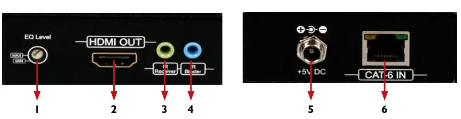
- SIGNAL LEVEL: Adjust the 8-level equalization
- HDMI OUTPUT: Connect to HDTV with a HDMI cable
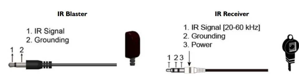
- IR RECEIVER: Plug in IR receiver
- IR BLASTER: Plug in IR blaster
- +5V DC: 5V DC power jack
- HDMI SIGNAL IN: Plug in a Cat.X cable
Signal Level (Max (0 – 7) Min)
Adjust the 8-level equalization control to the received HDMI signals. The HDMI signal level varies from 0 (strongest) to 7 (weakest) for respective transmission length from longest possible range to short distance. Please adjust the signal level from 7 to 0 and stop turning the rotary switch whenever the audio/video is playing normally. Inappropriate signal level setting may cause overpowering issue that would shorten the product life significantly!
IR CONTROL INSRTUCTIONS

- SW-HDM3D-C6-8x8E IR SOCKETS
- ALL IR OUT: The default location for IR blaster to transmit all IR command signals received from any of the four remote receivers to all of the HDMI sources.
- IR BLASTER 1-4: IR blaster connected here can only transmit IR command signals from the remote receivers that are setting at respective input channel from 1 to 4.
- SYSTEM IR: Receives IR commands from remote control
- HDM3D-C6SW-R
- IR BLASTER: IR control on individual display device
- IR RECEIVER: IR receiver connected here can receive all IR command signals from the IR remote controls of
- SW-HDM3D-C6-8x8E and all other HDMI source devices.

INSTALLATION SWHDM3D-C6-4X4E
Matrix Switch
- Connect all sources to HDMI Inputs on the Matrix Switch (SW-HDM3D-C6-4x4E)
- Connect each HDMI CAT 5/6 output on the SW-HDM3D-C6-4x4E to respective CAT 5/6 input on the remote receiver HDM3D-C6SW-R
- Connect IR BLASTER cable to the SW-HDM3D-C6-4x4E and direct the IR emitter to the build-in IR receiver of the sources
- Connect the +5V 6A DC power supply to the SW-HDM3D-C6-4x4E
- Power on all HDMI sources
- Power on the SW-HDM3D-C6-4x4E
Receiver
- Connect each HDMI output to HDMI displays.
- Connect the CAT5E/6 INPUT on the HDM3D-C5SW-R to the CAT5E/6 OUTPUT port on the SW-HDM3D-C6-4x4E.
- Connect IR receiver and place the IR receiver at the appropriate position that can receive the IR command signals sent from the users.
- Dial the 8-level rotary control switch to adjust the HDMI signal level until the picture and sound are clear. It is recommended to dial from 7 to 0 to find the optimal visual experience
FRONT PANEL OPERATION GUIDE
IN/OUT MAP
- Use the “+”or “-“ output push button to select the number of display
- Use the “+”or “-“ input push button to select the number of input source
- “+”: change selected input/output port in ascending order
- “-” : change selected input/output port in descending order
- After you select the desired input/output port, the LED will blink twice and the setting will be effective
SAVE MAPPING MODE
- K eep pushing “output+ (save)”button until the output LED shows “d.” to enter the Save Mapping Mode.
- Use the “+”or “-“ input push button to select the mapping configuration (0~7) which you want to save current input/output mapping
- After you select the desired mapping configuration number, the LED will blink twice and the mapping setting will be saved
- If you push the “output- (preset)”button before the mapping setting is saved, the LED will show “_”“_”to quit the Save Mapping Mode
PRESET MAPPING MODE
- K eep pushing “output- (preset)”button until the output LED shows “P.” to enter the Preset Mapping Mode.
- Use the “+”or “-“ input push button to select the saved mapping configuration (0~7) which you want to recall
- After you select the desired mapping configuration number, the LED will blink twice and the mapping setting will be effective
- If you push the “output+ (save)”button before the mapping setting is effective, the LED will show “_”“_”to quit the Preset Mapping Mode
DEFAULT EDID MODE
- Push “input+ (default)”button to select the input channel which you want to learn default EDID and then keep pushing “input+ (default)”button when you select your desired input channel
- Push the “+”or “-” output push button and then the LED will show “E”“d” one time to enter Learn Default
EDID Mode
- Use “+”or “-” output push button to select the default EDID mode(1~8)
- Release “input+ (default)”button after selecting the desired default EDID mode, and then the LED will blink twice and the setting will be effective
- It will quit the Learn Default EDID Mode if you push the “input- (learn)”button before the setting is effective
- The LED will show “0”“0” if the setting is success
- The LED will show “F”“F” if the setting is failure
EDID LEARNING MODE
- Push “input- (learn)”button to select the input channel which you want to learn EDID from EDID Port and then keep pushing “input- (learn)”button when you select your desired input channel
- P ush the “+”or “-” output push button and then the LED will show “E”“L” one time to enter Learn Output
EDID Mode
- Use “+”or “-” output push button to select EDID Port(number 4)
- Release “input- (learn)”button after selecting the EDID Port number, and then the LED will blink twice and the setting will be effective
- It will quit the Learn Output EDID Mode if you push the “input+ (default)”button before the setting is effective
- The LED will show “0”“0” if the setting is success
- The LED will show “F”“F” if the setting is failure
RS232 & ETHERNET SOFTWARE GUIDE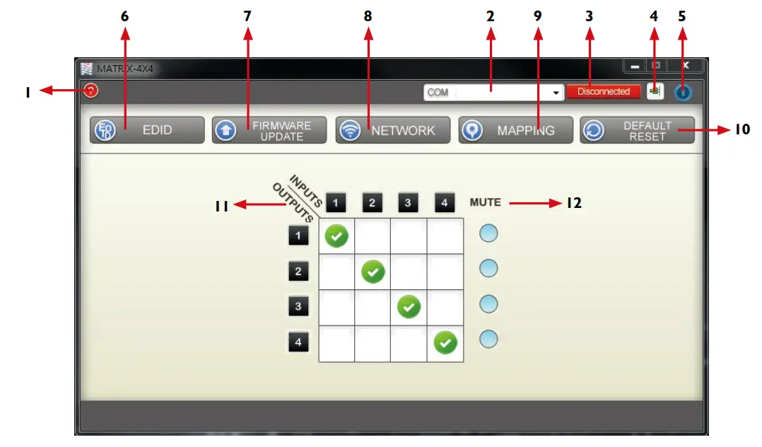
- FW/SW Version Button
- COM Port Selection
- Connection Status
- Connect/Disconnect Button
- Power On/Off Button
- EDID Button
- Firmware Update Button
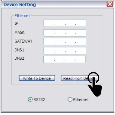
- Network Button
- Mapping Button
- Default Reset Button
- In/Out Switch Button
- Mute Output Button
FW/SW VERSION BUTTON
Click “![]() ” button to show version information
” button to show version information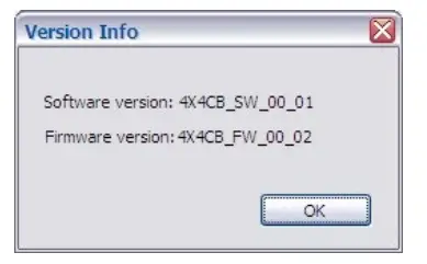
COM PORT SELECTION
Click “![]() ” button to select com port
” button to select com port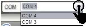
CONNECTION STATUS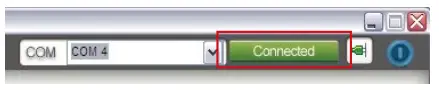
- Connected status:

- Connecting status:

- Disconnected status:
CONNECT/DISCONNECT BUTTON
Click this button “ ![]() ” to change connection status
” to change connection status
POWER ON/OFF BUTTON
- Click this button to power on/off

 Power on status (BLU E): click this button to power off device (standby mode)
- “
 ” Power off status (RED): click this button to power on device

EDID BUTTON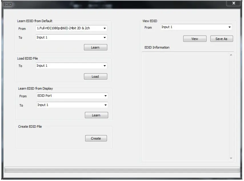
CREATE EDID FILE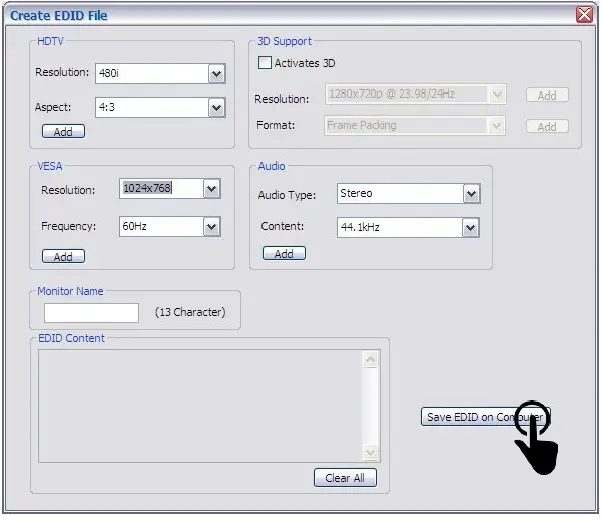
VIEW EDID CONTENT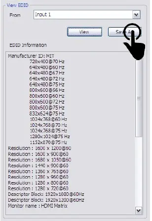
FIRMWARE UPDATE BUTTON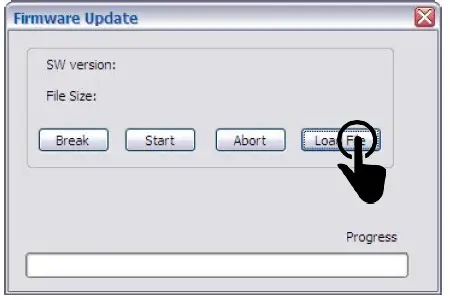
MAPPING BUTTON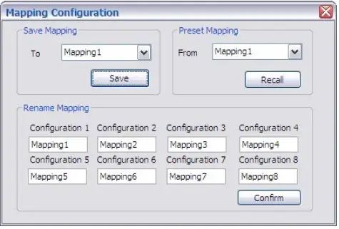
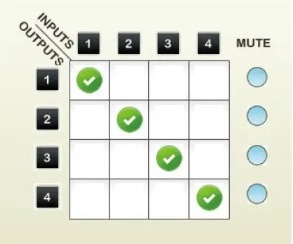
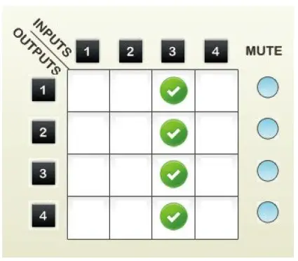
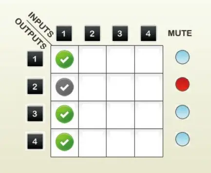
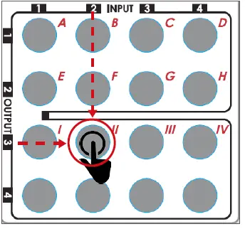
IN/OUT SWITCH BUTTON
- Click the button on the checkerboard to select input & output port

- User can click the input number button to let all outputs select the same input Ex: all outputs select input 3

MUTE OUTPUT BUTTON
- Click the circle button to turn off output’s video and audio
- Ex: mute output 2

EDID LEARNING
There Are Eight Embedded Default Edid As Below,
- FULL-HD (1080P@60)-24BIT 2D & 2CH
- FULL-HD (1080P@60)-24BIT 2D & 7.1CH
- FULL-HD (1080P@60)-24BIT 3D & 2CH
- FULL-HD (1080P@60)-24BIT 3D & 7.1CH
- HD (1080I@60)(720P@60)-24BIT 2D & 2CH
- HD (1080I@60)(720P@60)-24BIT 2D & 7.1CH
- FULL-HD (1080P@60)-36BIT 2D & 2CH
- FULL-HD (1080P@60)-36BIT 2D & 7.1CH
SPECIFICATIONS
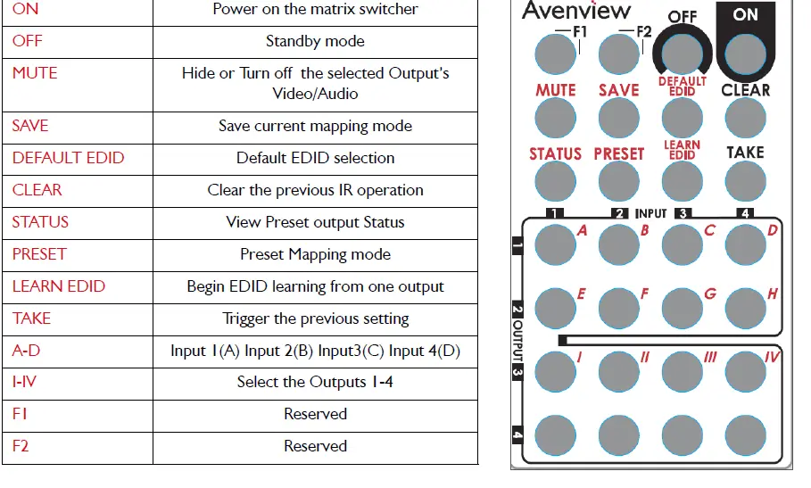
| ON | power on the matrix switcher |
| Off | Standby mode |
| MuTE | Hide or Turn off the selected Output’s Video/Audio |
| SAVE | Save current mapping mode |
| DEfAulT EDID | Default EDID selection |
| ClEAR | Clear the previous IR operation |
| STATuS | View preset output Status |
| pRESET | preset Mapping mode |
| lEARN EDID | Begin EDID learning from one output |
| TAkE | Trigger the previous setting |
| A-D | Input 1(A) Input 2(B) Input3(C) Input 4(D) |
| I-IV | Select the Outputs 1-4 |
| f1 | Reserved |
| f2 | Reserved |
IR CONTROL GUIDE
| OPERATION | PROCEDURE | 7-SEGMENT LED | |
| MuTE + A~D(OuTpuT 1~4) + TAkE | – 0 | ||
| MuTE OuTpuT
EX: MuTE OuTpuT 3 | 1. pRESS “MuTE” BuTTON
2. pRESS NuMBER kEy “C” TO SElECT OuTpuT 3 | 3
0 3 | |
| 3.pRESS “TAkE” BuTTON | 0 | ||
|
OuTpuT STATuS EX: OuTpuT 4 (INpuT 2) | STATuS + A~D(OuTpuT 1~4) + TAkE 1.pRESS “STATuS” BuTTON
2. pRESS NuMBER kEy “D” TO SElECT OuTpuT 4 3. pRESS “TAkE” BuTTON | –
– 4 – 4 2 | |
|
SAVE CuRRENT MAppING MAppING TO 5 | SAVE + A~H(1-8 STORAGE SITE) + TAkE 1.pRESS “SAVE” BuTTON
2. pRESS NuMBER kEy “E” TO SElECT THE STORAGE SITE 5 3. pRESS “TAkE” BuTTON | d
– d 5 | |
|
pRESET MAppING EX: pRESET SAVED MAppING fROM 5 | pRESET + A~H(1-8 STORAGE SITE) + TAkE 1.pRESS “pRESET” BuTTON
2. pRESS NuMBER kEy “E” TO SElECT THE STORAGE SITE 5 3. pRESS “TAkE” BuTTON | p
– p 5 | |
| DEfAulT EDID + A~H(1-8 DEfAulT EDID) +?~?(INpuT | E
d 2 d 2 3 0 0 (success) | ||
| 1~4) + TAkE | |||
| lEARN DEfAulT EDID | |||
| EX: DEfAulT EDID 2
INpuT 3 | 1. pRESS “DEfAulT EDID” BuTTON
2. pRESS NuMBER kEy “B” TO SElECT DEfAulT EDID 2 3. pRESS NuMBER kEy “?” TO SElECT INpuT 3 |
f f (fail) | |
| 4.pRESS “TAkE” BuTTON | |||
| lEARN + D(EDID pORT) +A~D(INpuT 1~4) + TAkE | E
l | ||
| lEARN EDID pORT EDID
EX: lEARN EDID pORT INpuT 3 |
1. pRESS “lEARN” BuTTON 2. pRESS NuMBER kEy “D” TO SElECT EDID pORT 3. pRESS NuMBER kEy “C” TO SElECT INpuT 3 4.pRESS “TAkE” BuTTON | 4
l 4 3 0 (success) |
f f (fail) |
TECHNICAL SUPPORT
- 186605080269
- [email protected]
FAQS
The MultiViewer simultaneously displays the video signals from four digital or analog computer or video sources on one screen. If more than four video signals are to be displayed simultaneously on one screen, several MultiViewer can be cascaded. Each video signal can be displayed in any size and position on the screen.
multiviewer (plural multiviewers) A combination of software and hardware permitting multiple displays to be shown together on a single display.
Featuring 4 6G-SDI inputs with full re-synchronization, MultiView 4 lets you monitor any combination of SD, HD and Ultra HD video formats and frame rates all at the same time
A multiviewer is similar to a video wall. But while video walls require a separate TV display for each video source, multiviewers only require one TV display. Multiviewers are able to showcase full, split, quad, and custom configurations on the TV display.
MultiView and View controls allow you to divide the content of a page into different groups, displaying only one group at a time. Each View control manages one group of content and all the View controls are held together in a MultiView control.
The SPLITMUX® Low-Cost HDMI Dual Screen Splitter/Multiviewer allows you to simultaneously display real-time HDMI/DVI video from two different sources on a single monitor. It is capable of displaying the video sources in dual, PiP or full screen mode.
Most good monitors now have multiple inputs, just as televisions do. Two HDMI or Displayport sockets is fairly common, but you may also have a monitor with a mix of VGA, DVI and HDMI. It all depends on its age and model.
Although six different sides can be drawn, usually three views of a drawing give enough information to make a three-dimensional object. These views are known as front view, top view and end view.
You can move between views by setting the MultiView control’s ActiveViewIndex property to the index value of the View control to display
Multi-view depth is highly accurate but only in high-texture areas and high-parallax cases. Single-view depth captures the local structure of mid-level regions, including texture-less areas, but the estimated depth lacks global coherence
In multiview drawings, generally three views of an object are drawn, and the features and dimensions in each view accurately represent those of the object.
Multiview projections are a collection of flat 2-D drawings of the different sides of an object. Only two forms of orthographic projections are used: first-angle (‘European ISO-E’) and third-angle (‘American ISO-A’).
Left side view – shows what becomes the left side of the object after establishing the front view position. Right side view – shows what becomes the right side of the object after establishing the front view position.
An orthographic projection is a way of representing a 3D object by using several 2D views of the object. Orthographic drawings are also known as multiviews. The most commonly used views are top, front, and right side
You can move between views by setting the MultiView control’s ActiveViewIndex property to the index value of the View control to display.


