MUNBYN IMC01 Banknote Counter Instruction Manual

IMC01 Banknote Counter Maintenance Manual
Document Name: IMC01 Maintenance Manual-1.03.docx
Name | Signature | Date | |
| Prepared by: | Byron Zhong | ||
| Reviewed by: | |||
| Approved by: |
Version History
| Date | By | By Changes | Version |
| 2020-11-18 | Byron Zhong |
| 1.00 |
| 2020-11-20 | Byron Zhong |
| 1.01 |
| 2020-11-23 | Byron Zhong |
| 1.02 |
| 2021-1-12 | Byron Zhong |
| 1.03 |
1.0. Overview
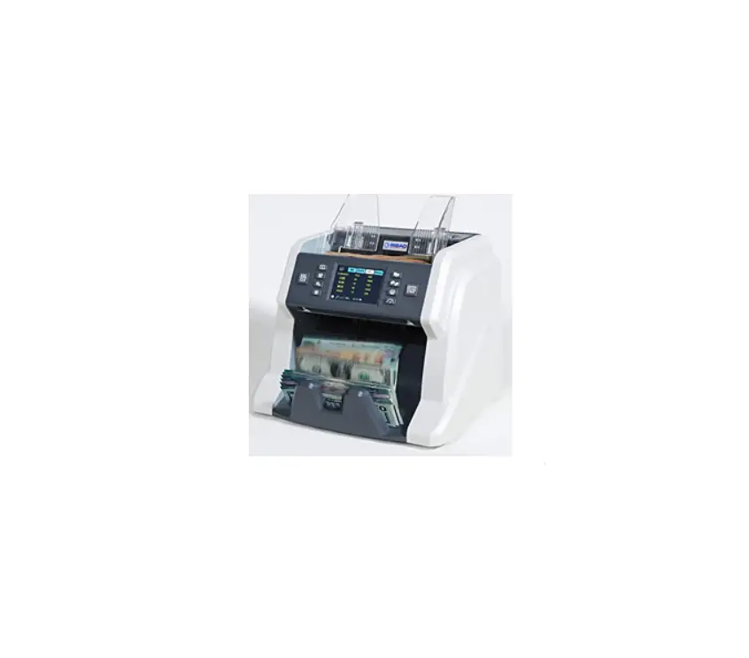
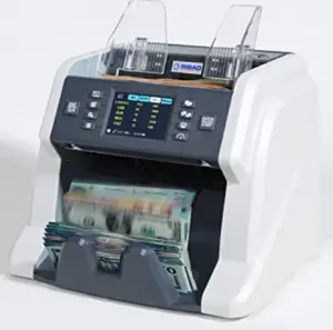
Thank you for purchasing our banknote counters IMC01.
After starting the machine, it will go on self-check automatically. If the preset window shows the error code or tell you to clean the sensors, generally speaking, it is because of dust on the surface or sensor blocked by notes. So please clear the dust on the surface with brush or soft cloth, or take the notes away. Then restart the machine. This document describes the error handling guideline and the maintenance manual.
2.0. Cleaning the Machine
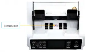
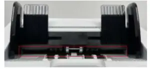
There are 3 parts need to be clean in the hopper: hopper sensor, banknote processing wheel and the banknote entrance.
- Hopper Sensor.

Figure 2-1 Hopper Sensor
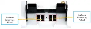
As shown at the above figure, clean the hopper sensor with nylon brush or cleaning cloth. - Banknote processing wheel As shown in the following figure, clean the banknote processing wheel with nylon brush or cleaning cloth.

Figure 2-2 Banknote Processing Wheel - Banknote entrance As shown in the following figure, clean the banknote entrance with nylon brush.

2.2. Clean the Stacker Sensors
As shown in the following figure, clean the stacker sensors with nylon brush or cleaning cloth.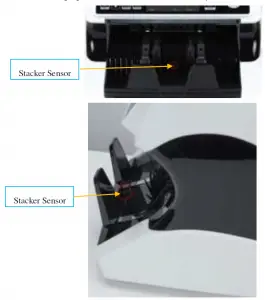
Figure 2-4 Stacker Sensors
2.3. Clean the Internal Sensors
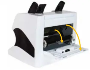
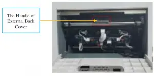
Figure 2-5 Direction of Back Cover Opening
- Pull the handle of external back cover with the direction shown in Figure 2-5 to open the back cover.

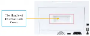
Figure 2-6 Handle of External Back Cover - Pull the handle of internal back covering the direction shown in Figure 2-5 to open it.

Figure 2-7 Handle of Internal Back Cover - Clean the lower CIS and Lower UV sensors with cleaning cloth or nylon brush respectively.

Figure 2-8 Lower Sensors - Clean the upper CIS with cleaning cloth

Figure 2-9 Upper CIS Sensor

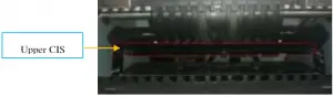
Note: For the CIS sensors, it is recommended to used cleaning cloth to clean them.
3.0. Error Analysis
3.1. Error Code
| Code | Error Description | Handling Method (Recommendation) |
| E1 | Bill UV sensor error | Clean the UV sensor with brush or cloth. |
| E2 | Bill double error | Check the bill, clean the machine and fine tune the screw counterclockwise |
| E3 | Chain notes error | Check the bill, clean the machine and fine tune the screw counterclockwise |
| E4 | Half notes error | Check the bill, clean the machine, and fine tune the screw clockwise |
| E10 | Bill CIS sensor signal lose | Clean the CIS sensor, and calibrate the CIS |
| E11 | Denomination error | Clean the CIS sensor |
| E12 | Bill denomination error | Check the bill, clean the CIS sensor |
| E13 | Bill facing recognize error | Not applicable |
| E14 | Bill size recognize error | Check the bill, and clean the machine |
| E15 | Bill towards recognize error | Not applicable |
| E20 | MT error | Check the bill, and clean the machine |
| E21 | MG1 error | |
| E22 | MG2 error | |
| E23 | MG3 error | |
| E24 | MG4 error | |
| E30 | IR transmission area 1 error | |
| E31 | IR transmission area 2 error | |
| E32 | IR transmission area 3 error | |
| E33 | IR transmission area 4 error | |
| E34 | IR transmission area 5 error | |
| E35 | IR transmission area 6 error | |
| E36 | IR transmission area 7 error | |
| E37 | IR transmission area 8 error | |
| E38 | IR reflect area 1 error | |
In the process of using the IMC01, the IMC01 may show abnormal state and display the error codes on the
screen. The description of the error codes and the related handling method is shown in table 3-1.
3.2. Bill Jam
If the bills are stuck inside the machine, please turn off the machine and rotate the banknote processing wheel by the direction of the following figure to take the jammed bills.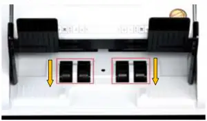
Figure 3-1 The Direction of Wheel Rotation to Take the Jammed Bill
- The bill size is out of the range according to IMC01 specification.
- The banknote is damaged with different ways such as lack of corner, tape, hole, tear and folded. As shown in Figure 3-2, it is not recommended to count this kind of bills

Figure 3-2 Bill Damaged Ways - he banknote entrance is so small that the banknote cannot pass through it smoothly. In this case, you need to fine tune the screw by rotating it clockwise according to section 4.1.
- Other abnormal operation or there is unknown thing inside the IMC01.If something inside the IMC01, you need to open the back cover to check, and clean the internal sensors.

3.3. Sensor Errors
The IMC01 banknote counter will take a few seconds to conduct a self-check with spinning the counting wheels after power on. The IMC01 will check the sensors, the following errors may happen if the sensors have been blocked or damaged.
3.3.1. Hopper Sensor Error
If the wheels in the hopper is always spinning, and then stop with the “hopper sensor error” or “main motor error” indicated on the screen, that means the hopper sensor is too sensitive.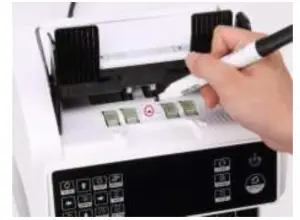
Figure 3-3 Use Marker Pen to Decrease the Sensitivity of Hopper Sensor
Please use the marker pen to paint a little on the hopper sensor as shown in the above figure. If the wheels don’t move when you place the bill on the hopper by enabling the auto counting, that means the hopper sensor doesn’t work If you meet the above hopper sensor errors, please follow the instruction of hopper sensor maintenance according to section 4.3.1
3.3.2. Stacker Sensor Error
If the impeller is always spinning, or the “stacker sensor error” indicated on the screen, that means the stacker sensor doesn’t work or too sensitive. Please follow the instruction of the stacker sensor maintenance according to section 4.3.2.
3.3.3. Counting Sensor Error
If the number of banknote counting is always not correct, or the “Main Motor Error” is shown on the screen, that means the counting sensor error doesn’t work. Please clean the machine first. If the error still happens, please follow the instruction of the counting sensor error maintenance according to
section 4.3.3.
4.0. Maintenance
4.1. Fine Tuning the Adjustable Screw

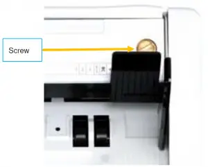
Figure 4-1 The Adjustable Screw
The screw is used to control the width of the banknote entrance. The width will become smaller by rotating the screw toward the smallest dot, otherwise, it will become bigger.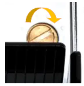
Figure 4-2 Rotate the Screw to Increase the Width of Banknote Entrance
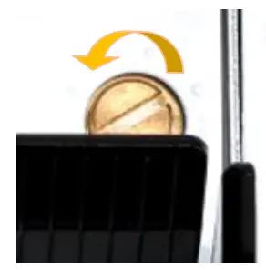
Figure 4-3 Rotate the Screw to Decrease the Width of Banknote Entrance
In order to fine tune the screw, please stop the auto counting first, and insert one banknote to the gap between the rollers to check if the banknote can be inserted smoothly, as shown in the following
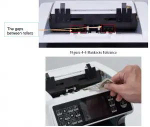
Figure 4-5 One banknote to Check the Gap between the Rollers
Moving the banknote between the gap, and rotate the screw, and then check the other gap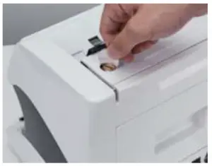
Figure 4-6 One Coin to Rotate the Screw
Tips: you can just use one coin to rotate the screw
4.2. CIS Calibration
CIS calibration is needed when there are many errors during the banknote counting process.
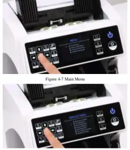
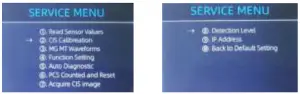
- Please enter the menu interface. And go to the service menu with the password “9999”, as shown in the following figures.

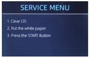
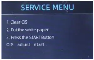
- Click the “CIS Calibration” option, the screen will be shown in the following figure.

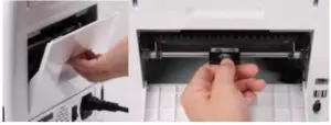
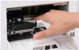
Figure 4-9 CIS Calibration Interface - Open the back cover to clean the CIS sensors with cleaning cloth.

Figure 4-10 Open the Back Covers
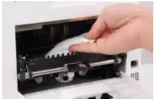
Figure 4-11 Clean the Lower CIS - Put the CIS calibration paper (white paper) inside, and close the back covers
Figure 4-13 Place the CIS Calibration Paper - Start CIS calibration by pressing the “RESTART” button

- After finish, just take the calibration paper out and close the covers, and then turn off the machine.
- Turn on the machine to finish the CIS calibration.
4.3. Back to Default Setting
After fine tuning the screw and CIS calibration, if there are still some errors or the counting is still not correct, returning to the factory default setting mode is required
- Enter the menu interface, and go to the service menu with the password “9999”, as shown in the following figures.

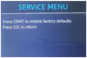
Figure 4-15 Service Menu - As shown in above figure, choose “⑩. Back to Default Setting” and enter the menu key. It will enter to the following display on the screen.

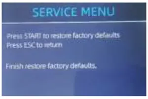
Figure 4-16 Default Setting Interface - Press the RESTART key, the IMC01 will reset all the changed settings before.
Figure 4-17 Default Setting Guide - Go back the main screen, and the use your finger to touch the hopper sensor. The processing wheels and rollers in the IMC01 will run for a while.

4.4. Sensors Replacement
4.4.1. Hopper Sensor
Please contact and return to us for repairment.
4.4.2. Stacker Sensor
Please contact and return to us for repairment.
4.4.3. Counting Sensor
Please contact and return to us for repairment.
4.5. Power Board Replacement
Please contact and return to us for repairment.
4.6. Mainboard Replacement
Please contact and return to us for repairment.

Scan the QR code for Facebook online chat


