
![]()
A10T manual
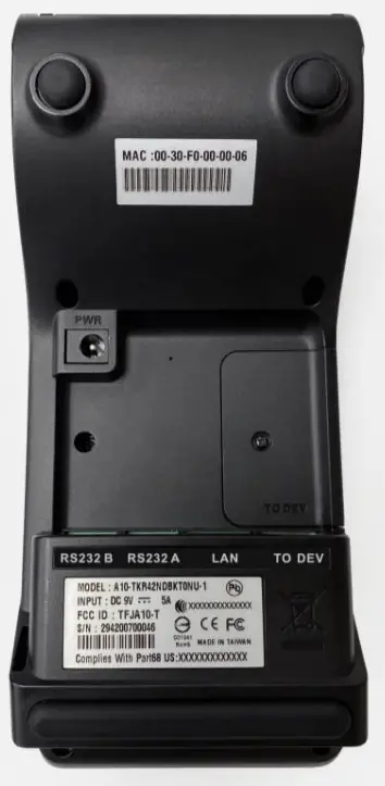
Payment Terminal A10-T
The A10-T is a compact payment terminal, designed to support financial inclusion scenarios as well as innovative payment schemes in mature markets.
Specification
| Processor | Microchip SAMA5D28 | |
| Memory | DDR2 128MB | |
| Storage | Flash 256MB | |
| Display | 2.8″ IPS 320×240 | |
| OS | Linux | |
| Audio | Buzzer (Default) Speaker x1 (PCBA Reserved) Buzzer Sound Pressure Leve1:70 dB/10cm(2.5KHz) | |
| Reader | ||
| Magnetic Card Reader | Bi-directional, support triple tracks IS07811 Speed 5 to 40 IPS 1,000,000. swipe times | |
| Smart Card Reader | IS07816, T=0 , T=1 EMV Level 1, Support 5V/3V 500,000. inserted times | |
| Contactless | IS014443A&B, MIFARE HW Ready for NFC | |
| Printer | 384dots/lines,105mm/paper roll 58mm x 0 40 mm paper thickness 60-80um | |
| 3G/4G (optional) | ME3630 (for FCC ID: TFJA10-T-ME) GM500-U1A (for FCC ID: TFJA10-T-GM) | |
| I/O Connector | ||
| RJ11 | RS232 x1 RI (as VCC5V/9V by cable), Baud rate 115200 bps | |
| RJ11 | RS232 x1 RI (as VCC 9V), RTS/CTS, Baud rate 115200 bps | Modem x1(default) V.92, V.32bis, V80 14400, 12000, 9600,7200 BPS |
| RJ45 | x1 (Ethernet) 10BASE-T/100BASE-T | |
| USB | USB1 x1 Host USB2 x1 Host\Device (detect pin) (USB port A for SAMBA) USB2.0 | |
| DC Jack | xl |
| SAM | X0, x4(optional) |
| SIM | x1 (optional) |
| Debug console | 2.54mm Head X1(2pin) |
| LED indicator | Mono, Green X4 for EMV |
| Keypad | Rubber Keys *18 (Func. keys*3, STD Keys *15) |
| Environment | |
| Operating Temperature | 0°C to +40°C |
| Storage Temperature | -20°C to +70°C |
| Humidity | 5% to 90% |
| Reliability Requirements | |
| MTBF | 100,000 hours |
| Drop test | 76 cm without damage |
| ESD | Air : +/-15KV Contact : +/- 8KV |
| Key button | 1M times |
| Battery Life | 5 years |
| SW requirement | |
| EMV card Logo | Card brand logo on LCD |
| Installation guide (USB Interface) | |
| 1 | Plug the adapter. |
| 2 | Plug the USB cable to the USB port of PC. |
| 3 | Install the driver |
 |  |
FEDERAL COMMUNICATIONS COMMISSION INTERFERENCE STATEMENT
This equipment has been tested and found to comply with the limits for a Class B digital device, pursuant to part 15 of the FCC Rules. These limits are designed to provide reasonable protection against harmful interference in a residential installation. This equipment generates, uses, and can radiate radio frequency energy and, if not installed and used in accordance with the instructions, may cause harmful interference to radio communications. However, there is no guarantee that interference will not occur in a particular
installation. If this equipment does cause harmful interference to radio or television reception, which can be determined by turning the equipment off and on, the user is encouraged to try to correct the interference by one or more of the following measures:
- Reorient or relocate the receiving antenna.
- Increase the separation between the equipment and receiver.
- Connect the equipment into an outlet on a circuit different from that to which the receiver is connected.
- Consult the dealer or an experienced radio/ TV technician for help.
CAUTION:
Any changes or modifications not expressly approved by the grantee of this device could void the user’s authority to operate the equipment.
This device complies with Part 15 of the FCC Rules. Operation is subject to the following two conditions: (1) this device may not cause harmful interference, and (2) this device must accept any interference received, including interference that may cause undesired operation.
RF Exposure Information (SAR)
This device meets the government’s requirements for exposure to radio waves. This device is designed and manufactured not to exceed the emission limits for exposure to radiofrequency (RF) energy set by the Federal Communications Commission of the U.S. Government.
The exposure standard employs a unit of measurement known as the Specific Absorption Rate, or SAR. The SAR limit set by the FCC is 1.6 W/kg. Tests for SAR are conducted using standard operating positions accepted by the FCC with the EUT transmitting at the specified power level in different channels.


