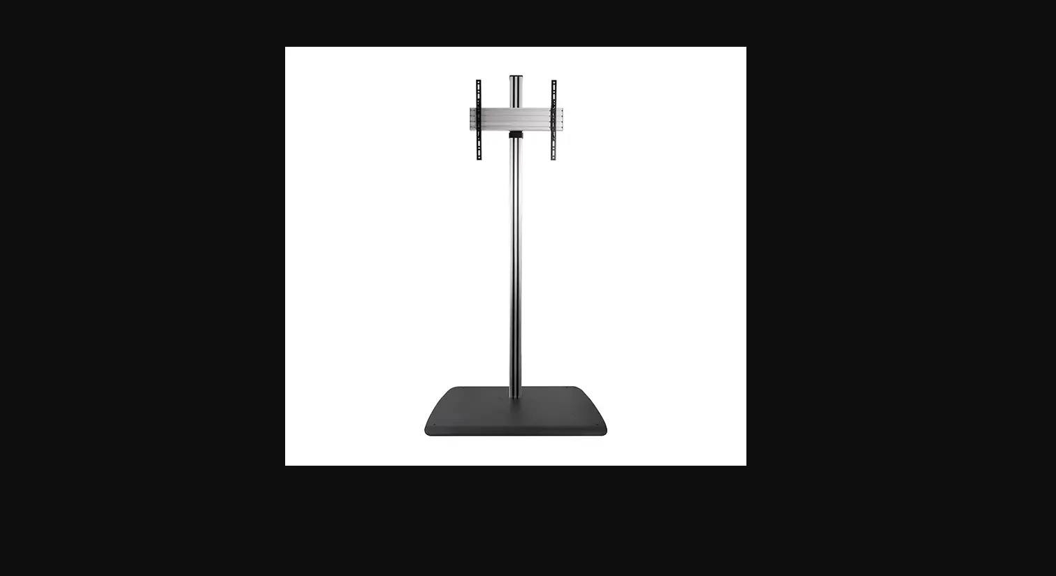
BTF840 Universal Flat Screen Stand
BTF840
UNIVERSAL
FLAT SCREEN STAND
INSTALLATION GUIDE
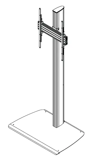
SPECIFICATIONS
- Recommended for screens up to: 75″ (190cm)
- Max load: 70kg (154lbs)
- Suitable for displays with VESA® and non-VESA fixings up to 600 x 400mm
- Suitable for mounting screens in a landscape or portrait orientation
- Integrated cable management
- Dimensions: W: 890mm (35′′) H: 1840mm (72.5″) D : 604mm (23.8 ” ) 2
- Simple hook-on installation, all mounting hardware included
![]()
INSTALLATION SAFETY INSTRUCTIONS
CAUTION: This stand is intended for use only with the maximum weights indicated. Use with equipment heavier than the maximum indicated may result in instability causing possible injury.
Do not attempt to install this product until all instructions and warnings have been read and properly understood . Please keep these instructions for future reference.
Please check carefully to make sure there are no missing or defective parts defective parts must never be used. B- Tech AV Mounts, its distributors and dealers are not liable or responsible for damage or injury caused by improper installation , improper use or failure to observe these safety instructions. In such cases, all guarantees will expire .
General
B- Tech AV Mounts recommends that a professional AV installer or other suitably qualified person install this product . Great care must always be taken during installation as most AV equipment is of a fragile nature, possibly heavy and easily damaged if dropped .
If you do not fully understand the instructions or are not sure how to install this product safely, then please consult a professional for advice and/or to install this product for you. Failure to mount this product correctly may cause serious injury or death, both during installation and at any time thereafter.
Do not mount any AV equipment that exceeds the specific weight limit of the product you are installing.
This weight limit will be clearly stated on each product and its packaging and will vary from product to product.
Product location
Please pay careful attention to where this product is located . Designed for indoor use, this mount is suitable for public or home installation. Check load capacity of the floor prior to installation as some surfaces are not suitable for installation. When verifying the stability of the structure, consider the following external factors: The strength of the floor , exposure to sudden and severe wind and danger arising from contact with people and / or objects ( eg installations in passageways, emergency exits), if located in a public or frequently populated area ensure that the product is out of the immediate reach of people. When drilling holes it is essential to avoid contact with electrical cables and water or gas pipes contained within .
Fixing hardware
It is highly recommended that all fixing screws be used where supplied and that the purpose of all other fixing hardware is fully understood. In some cases more AV equipment fixing hardware will be supplied to accommodate different models of equipment and set up configurations . The installer must be satisfied that any supplied fixing hardware is suitable for each specific installation .
If any fixing screws or included hardware are deemed not sufficient for a safe installation then please consult a professional or your local hardware store .
Hazard limitations
When routing cables take advantage of any built in cable management features that the product might provide and ensure that all cables are tidy and secure. Check to see that any moving aspect of the product can do so unhindered by any cabling. Some products have moving parts and the potential to cause injury through the crushing or trapping of fingers or other body parts. Particular attention to the nature of moving parts is required especially when assembling installing and adjusting during set up. Immediately after installation double-check that the work done is safe and secure. Double-check all necessary fixings are present and are of ample tightness.
It is recommended that periodic inspections of the product and its fixing points are made as frequently as possible (no more than 6 months apart) to ensure that safety is maintained.
If in doubt consult a professional AV installer or other suitably qualified person.
B-Tech AV Mounts recommends that the product be installed by an AV installer or other person with adequate knowledge . B-Tech AV Mounts , its dealers, and its partners do not take responsibility for product damage or injury resulting from failure to follow these safety instructions . In some cases , there are places where the product is not suitable for installation, so pay special attention to the installation location . Pay attention to the installation position of the product and check it . Do not mount AV equipment that exceeds the specified weight limit .
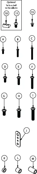
BTF840 PARTS LIST
PLEASE KEEP THIS FOR FUTURE REFERENCE (B)
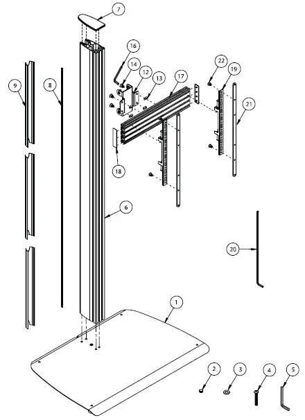
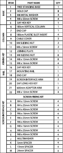
Suitable for loads up to 70kg (154lbs)
INSTALLATION INSTRUCTIONS
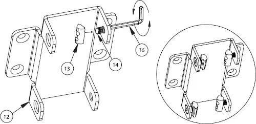
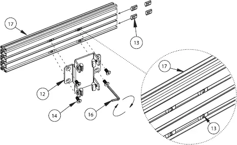
1. ATTACH JOINING PLATE TO RAIL
i. Prepare item 12 by assembling 4x item 14 to item 13.
ii. Insert 4x item 13 into item 17. 2x the bottom channel and 2x in the second channel.
Position the nuts centrally on the rail and attach item 12 to item 17 using item 14.
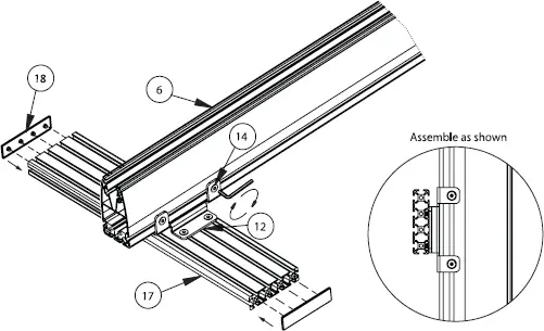
2. ATTACH RAIL TO COLUMN
i. Lay item 6 on the floor and slide on item 12.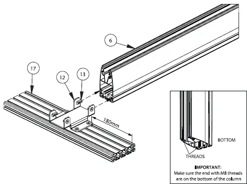
ii. Position item 12 at the preferred height on item 6 and tighten item 14.
iii. Add item 18 to the ends of item 17.
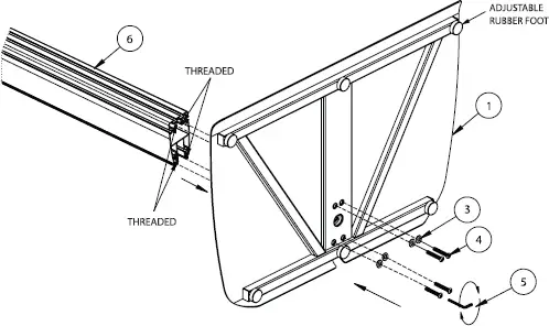
3. ASSEMBLE BASE TO COLUMN
Attach item 6 to item 1 using items 3 & 4.
Once the base is securely fixed, return the stand to an upright position.
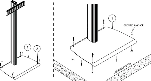
Optional Bolting the stand to the floor
Remove item 2 and adjustable rubber feet from item 1.
Pre-drill holes in floor and using suitable ground anchor fixings (not supplied), fix stand to floor.
4. ATTACH INTERFACE ARMS TO SCREEN
Item 19 can mount screens with fixing patterns up to 400 x 400mm.
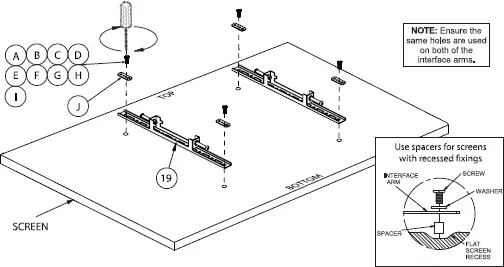
For screens with VESA 600 x 400mm fixings attach item 21 onto item 19 using item 22 before mounting to the back of the screen.
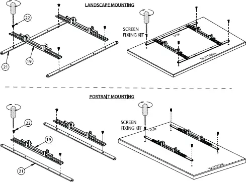
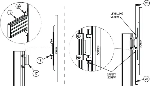
5. MOUNT SCREEN TO RAIL
i. Hook the screen onto the rail. (This may require 2 people).
ii. After the screen is mounted, if necessary adjust the height adjustment screws on top of the interface arms to level the screen and then once positioned correctly, tighten the safety screws at the bottom of item 19.
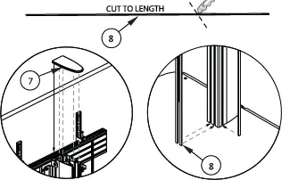
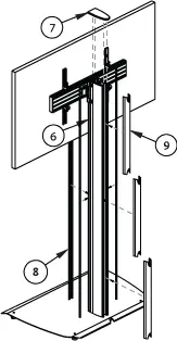
6. ADD COVERS AND INSERTS
i. After the screen cables are connected and routed down the back of
the item 6, partially clip on item 9, this allows easy removal if more cables need adding.
Once satisfied all cables are fitted, clip the covers on fully.
ii. Fit item 7 to the top of item 6.
iii. With a knife, cut to length item 8 and insert to the front and sides of item 6.
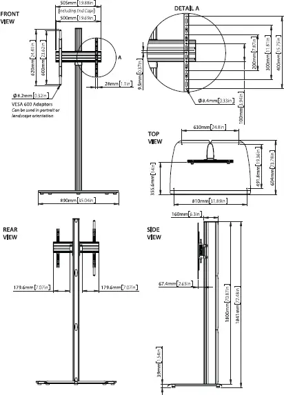
BTF840 DIMENSIONS
PLEASE KEEP THIS FOR FUTURE REFERENCE
THESE INSTRUCTIONS ARE INTENDED AS A GUIDE ONLY AND B-TECH ACCEPTS NO LIABILITY FOR THE ACCURACY OF THE INFORMATION CONTAINED IN THIS DOCUMENT.
CONTACT: [email protected]
©2022 B-Tech International Design and Manufacturing Ltd. All rights reserved.
B-Tech AV Mounts is a division of B-Tech International Design and Manufacturing Ltd.  B-Tech AV Mounts and the B-Tech logo are registered trade marks.
All other brands and product names are trademarks of their respective owners. Photographs are for illustrative purposes only. E&OE.
AMA-BTF840-V1-0822-BTECH MADE IN VIETNAM
For More Information Visit www.btechavmounts.com


