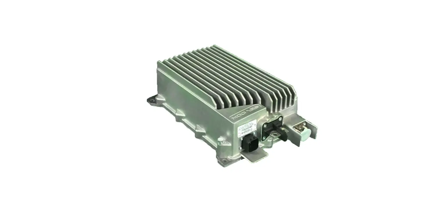
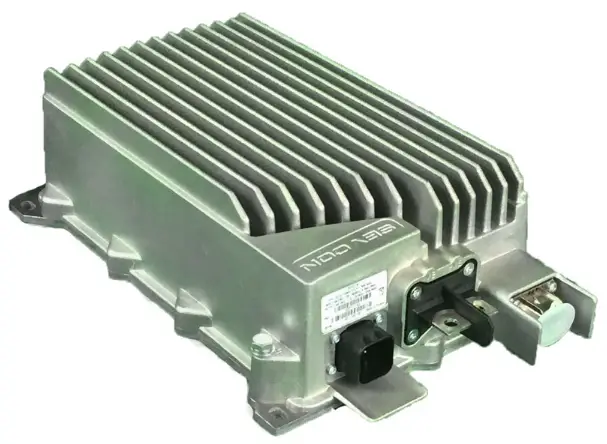
THUNDERSTRUCK MOTORS TSM-HV DC-DC Converter
Overview
The TSM HV DCDC converter adopts advanced high-frequency power electronic conversion technology. It is a high-performance vehicle-mounted DCDC converter specially developed for electric vehicles with high voltage traction systems. Following are the main features:
- Input and output are completely electrically isolated, safe and reliable
- The highest conversion efficiency exceeds 95%
- High power density and small volume
- Uses multi-stage power conversion technology, compatible with a wide input voltage range
- Uses soft switching technology to reduce power device losses and greatly improved EMC performance of the product
- Air cooled IP67 rated aluminum case with mounting points
- Utilizes dual controller digital architecture, with automatic protection and fault diagnosis functions
- High peak power and strong overload capacity, meeting the usage requirements of impact loads
- Includes optional CAN communication, BootLoader function, low voltage enable control, high voltage sleep and designated CAN message sleep function
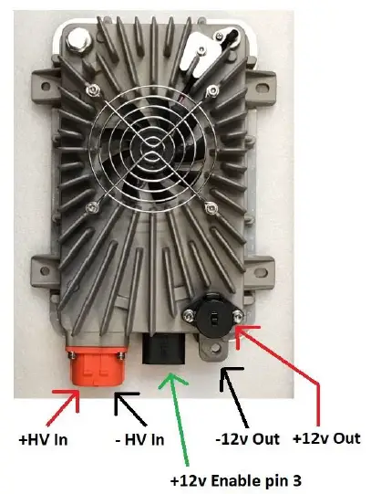
- Non-CAN operation is accomplished by connecting as shown in the diagram below

Environmental Conditions
| Item | Parameter | Value | Unit | Remarks |
| 1 | Working Temperature | -40 to +85 | ℃ | |
| 2 | Ambient Storage Temperature | -40 to +105 | ℃ | |
| 3 | Relative Humidity | 5 – 95 | % | Non-condensing |
| 4 | Cooling Method | Air-cooled | – | Outside the Shell |
| 5 | Protection Class | IP67 | – | Shell Part |
| 6 | Working Noise | <60 | dBA | Air Cooling System |
| 7 | Anti-vibration Leve | GB 413-2002 3.12 | – | Requirements for Non- engine Parts |
Electrical Performance
Input and Output Characteristics
| Item | Parameter | Value | Unit | Remarks |
| 1 | Input Voltage range | 280-450 | Vdc | 200~450 |
| 2 | Input Current | 6.8 | A | |
| 3 | Input Inrush Current | 8.2 | A | Capacitance spikes in 0.5 ms not Counted |
| 4 | Input current in standby | < 2 | ma | with 12v disconnected |
| Item | Parameter | Value | Unit | Remarks | |
| 1 | Rated Output Voltage | 13.8±0.2 | Vdc | Can be adjusted according to system requirements, the adjustment range is 10.8~15V | |
| 2 | Rated Output Power | 1500 | W | @Rated Input Voltage | |
| 3 | Peak output power | 1800 | W | @Rated Input Voltage | |
| 4 | Voltage Regulation | <±1 | % | Regulation Accuracy | |
| 5 | Load Regulation | <±1 | % | ||
| 6 | Current Reporting Error | <1 | A | <5A | Report Error |
| <0.5 | >5A | ||||
| 7 | Voltage Reporting Error | <0.2 | V | ||
| 8 | Current Control Error | <1 | A | Control Precision | |
| 9 | Voltage Control Accuracy | <0.2 | V | ||
| 10 | Work Efficiency | >94.5 | % | 40%~70% Load (Warm Up 2mi) | |
| >94.0 | 70%~100% Load (Warm Up 2min) | ||||
| >95.0 | Highest Efficiency | ||||
| 11 | Output current | 130±2 | A | ||
| 12 | Output Ripple and Noise | <240 | mVp -p | 20Mhz bandwidth, output connected to 10uF electrolytic capacitor and 0.1uF ceramic capacitor | |
| 13 | Transient Response | Overshoot amplitude | <5 | % | 30% -80% -30% load step change, amplitude 100A/ms |
| Recovery Time | <500 | µs | |||
| 14 | Output current while in stand by | ≤1 | mA | Secondary-side MCU enables sleep and wake-up through hard wire to ensure current at the output while standby | |
Protection and Control Functions
| Item | Parameter | Value | Unit | Remark | |
| 1 | Hard-wired Enable Control | Signal voltage | 9-16 | Vdc | When the hard-wire enable signal is input to the DC-DC, the DC-DC is turned on (default sleep); when the signal is floating or grounded, the DC-DC is turned off (default sleep). |
| Signal Current | 2 | mA | |||
| 2 | Input undervoltage protection | Protection point | 272±2 | Vdc | Instant protection, automatic recovery |
| Recovery point | 278±2 | Vdc | Instant protection, automatic recovery | ||
| 3 | Input Overvoltage Protection | Protection point | 458±2 | Vdc | Instant protection, automatic recovery |
| Recovery point | 452±2 | Vdc | Instant protection, automatic recovery | ||
| 4 | Output Undervoltage Protection | Protection point | 7.0±1 | Vdc | Instant protection, automatic recovery |
| Recovery point | 9.0±1 | Vdc | Instant protection, automatic recovery | ||
| 5 | Output Overvoltage Protection | Protection point | 16.0±0.5 | Vdc | If greater than protection point, turn off output |
| Recovery point | 15.5±0.5 | Vdc | If less than recovery point, works normally | ||
| 6 | Output Current Limit Protection | 130±2 | A | When the output current increases to the current limit protection point, it enters the constant current voltage limit mode | |
| 7 | Output Short Circuit Protection | – | Instant protection, automatic recovery | ||
| 8 | Input Reverse Connection Protection | DC-DC input does not start after reverse connection | – | ||
| 9 | Overheat Protection | Power attenuation | 100(Primary)/112( Secondary) | ℃ | When the temperature reaches the attenuation point, the module limits the power output; the power is attenuated at 8% / ℃ with, derated output. |
| Protection shutdown | 110(Primary)/118( Secondary) | ℃ | If met, turn off the output voltage | ||
| Protection Recovery | 95(Primary)/90( Secondary) | ℃ | If all met, work properly | ||
| 10 | CAN communication function | 1. With BootLoader function, software can be updated by CAN communication; 2. Can report DC-DC working status, input voltage, output voltage, output current, hardware failure, communication failure and other information; 3. Support hard-wired and arbitrarily formulated message sleep and wake-up. | |||
| Logical function | If the customer has no special logic requirements, the default is: 1. Enable hard-line control of DCDC converter on / off, high level start; 2. Enable hard-wired control for DCDC sleep and wake up, high level wake up. | ||||
Safety Regulations and EMC Characteristics
| Item | Parameter | Value | Unit | Remarks | |
| 1 | Withstand voltage | Input to Output | 2120 | Vdc | Leakage current ≤5mA, 1min, No breakdown, no flashover, basic insulation |
| Input to Earth | 2120 | Vdc | |||
| 2 | Insulation resistance | Input to Output | ≥50 | MΩ | Test Voltage 500Vdc |
| Input to Earth | ≥50 | MΩ | |||
| 3 | EMI | RE | GB / T 18655-2010, Chapter 6.4, CLASS 3 standard | – | |
| CE | |||||
| 4 | EMS | Radiation Immunity | GB/T 6113.1 | – | |
| High Current Injection | ISO 11452-4: 2005 Article 7, 100mA | ||||
| RF Immunity | ISO 11452-9 | ||||
| Conducted Immunity | ISO 7637-2: 2004 Article 5 | ||||
| Transient Conducted Immunity | ISO 7637-3: 2007 Article 3.4.2 | ||||
| Electrostatic Discharge | ISO 10650-2008 | ||||
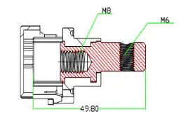
Structure and Interface Description
Structure size diagram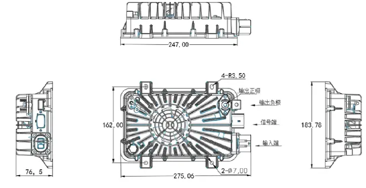
Interface definition
| Connector Pinouts | ||||
| Connector schematic | Name | Pin definition | Specifications | |
 | High Voltage Input connector | Input+ | 1 | REM-Z2PA-2.5-A |
| Input— | 2 | |||
 | DC Output Connector | Output+ | NA | ACTB142-C-N |
| M8 screw hole | Output- | Case | M8 bolt | |
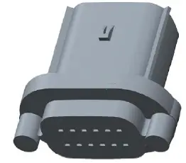 | Signal Connector | CANH | 5 | MOLEX 477259010
Note: the top left- hand pin is #1, increasing to the right, when viewing the low voltage receiving plug on the DCDC. |
| CANL | 6 | |||
| Enable | 3 | |||
| Output Ground | 1 |
Recommendations and Precautions
- Ensure that the input voltage is within the allowable input voltage range of the DC-DC converter.
- The converter is not equipped with an HV input fuse. It is recommended that the module be equipped with 15A / 600V fuse at the HV battery when using the module.
- Ensure that the input polarity is correct before connecting to the HV battery.
- Ensure that the output polarity is correct before connecting to the 12V auxiliary battery.
- The output side of the DCDC converter must be connected to a 12V auxiliary battery in order to operate.
- Do not mix or reverse the input and output wires.
- Avoid hot plugging the HV connector to avoid arcing. Due to the high power, make sure that the HV input connector is firmly connected before turning on the main power switch or contactor on the high-voltage side.
- Recommended to disconnect 12v positive output from the 12V auxiliary battery when DCDC is powered down. Options include use of a KSI or other relay of adequate current.


