SUNNY SF-B1423 BELT DRIVE INDOOR CYCLING BIKE
IMPORTANT! Please retain owner’s manual for maintenance and adjustment instructions. Your satisfaction is very important to us, PLEASE DO NOT RETURN UNTIL YOU HAVE CONTACTED US: [email protected] or 1- 877 – 90SUNNY (877-907- 8669).
IMPORTANT SAFETY INFORMATION
We thank you for choosing our product. To ensure your safety and health, please use this equipment correctly. It is important to read this entire manual before assembling and using the equipment. Safe and effective use can only be achieved if the equipment is assembled, maintained, and used properly. It is your responsibility to ensure that all users of the equipment are informed of all warnings and precautions.
- Before starting any exercise program, you should consult your physician to determine if you have any medical or physical conditions that could put your health and safety at risk or prevent you from using the equipment properly. Your physician’s advice is essential if you are taking medication that affects your heart rate, blood pressure, or cholesterol level.
- Be aware of your body’s signals. Incorrect or excessive exercise can damage your health. Stop exercising if you experience any of the following symptoms: pain, tightness in your chest, irregular heartbeat, shortness of breath, lightheadedness, dizziness, or feelings of nausea. If you do experience any of these conditions, you should consult your physician before continuing with your exercise program.
- Keep children and pets away from the equipment. The equipment is designed for adult use only.
- Use the equipment on a solid, flat level surface with a protective cover for your floor or carpet. To ensure safety, the equipment should have at least 2 feet (60 CM) of free space all around it.
- Ensure that all nuts and bolts are securely tightened before using the equipment. The safety of the equipment can only be maintained if it is regularly examined for damage and/or wear and tear.
- Always use the equipment as indicated. If you find any defective components while assembling or checking the equipment, or if you hear any unusual noises coming from the equipment during exercise, discontinue use of the equipment immediately and do not use until the problem has been rectified.
- Wear suitable clothing while using the equipment. Avoid wearing loose clothing that may become entangled in the equipment.
- Do not place fingers or objects into the moving parts of the equipment.
- The maximum weight capacity of this unit is 265 pounds (120 KG).
- The equipment is not suitable for therapeutic use.
- To avoid bodily injury and/or damage to the product or property, proper lifting and moving are required.
- Your product is intended for use in cool and dry conditions. You should avoid storage in extreme cold, hot or damp areas as this may lead to corrosion and other related problems.
- This equipment is designed for indoor and home use only; it is not intended for commercial use.
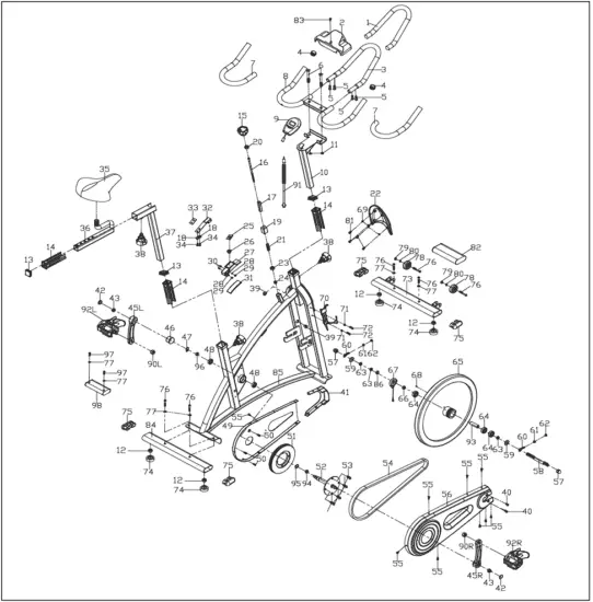
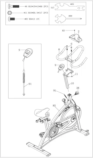
EXPLODED DIAGRAM
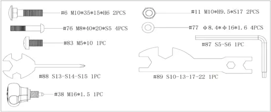
HARDWARE PACKAGE
PARTS LIST
| No. | Description | Spec. | Qty. |
| 1 | Foam (A) | Φ23*3*550 | 1 |
| 2 | Tablet Bracket | 1 | |
| 3 | Handlebar (A) | 1 | |
| 4 | End Cap | Φ25*16 | 2 |
| 5 | Screw | M6*16*S4 | 4 |
| 6 | Bolt | M10*35*15*H6 | 2 |
| 7 | Foam Grip | Φ23*3*460 | 2 |
| 8 | Handlebar (B) | 1 | |
| 9 | Computer | 1 | |
| 10 | Handlebar Post | 1 | |
| 11 | Nut | M10*H9.5*S17 | 2 |
| 12 | Nut | M8 | 4 |
| 13 | End Cap | F30*30*16 | 3 |
| 14 | Bushing | F38*F30*153.3 | 3 |
| 15 | Tension Control Knob | Φ58*44*M8*18 | 1 |
| 16 | Brake Rod | Φ10*210*M8*15*M6 *7*M10*95 | 1 |
| 17 | Bushing | 20*20*65 | 1 |
| 18 | Washer | D6*Φ12*1.2 | 2 |
| 19 | Square Nut | 15*15*25*M10 | 1 |
| 20 | Nut | M8*H5.5*S14 | 1 |
| 21 | Spring | Φ2.0*Φ15*54*N12 | 1 |
| 22 | Decorative Cover | 195*161*31 | 1 |
| 23 | Nut | M10*H5.5*S17 | 1 |
| 24 | Nut | M6*H11*S10 | 1 |
| 25 | Brake Stopper | 35*24*2 | 1 |
| 26 | Spring | Φ2*Φ24*Φ13*17*N4 | 1 |
| 27 | Brake Block | 110*27*30 | 1 |
| 28 | Washer | D5*Φ10*1 | 2 |
| 29 | Nut | M5*H5.5*S10 | 2 |
| 30 | Screw | M5*30*Φ8 | 2 |
| 31 | Woolen Felt | 110*30*10 | 1 |
| 32 | Spring Piece | T2*59*185 | 1 |
| 33 | Rubber Mat | 35*20*3 | 1 |
| 34 | Bolt | M6*12*S10 | 2 |
| 35 | Seat | 98-2 | 1 |
| 36 | Seat Slider | 1 | |
| 37 | Seat Post | 1 | |
| 38 | Adjustment Knob | M16*1.5 | 3 |
| 39 | Grommet | Φ12*11*Φ3 | 2 |
| 40 | Screw | M6*10*Φ12 | 2 |
| 41 | Front Cover | 157*152*38.5 HIPS | 1 |
| 42 | Crank Cap | Φ25*7 | 2 |
| 43 | Nut | M10*1.25*H7.5*S14 | 2 |
| 44L/R | (Refer to Part #92 L/R) | – | |
| 45L/R | Crank | 170 “L/R” 9/16 | 2 |
| 46 | Cover for Middle Axle | Φ50*Φ32*33 | 1 |
| 47 | C-clip | D17 | 1 |
| 48 | Bearing | 6203-2RS | 2 |
| 49 | Inner Belt Cover | 504*259*23 | 1 |
| 50 | Screw | ST4.2*16*Φ8 | 3 |
| 51 | Belt Wheel | Φ204*21*5PK | 1 |
| 52 | Middle Axle | 1 | |
| 53 | Screw | M10*16*S6 | 4 |
| 54 | Belt | 5PK520 | 1 |
| 55 | Screw | ST4.2*13*Φ8 | 9 |
| 56 | Outer Belt Cover | 648*264*45 | 1 |
| 57 | Nut | M12*1*H19.5*S19 | 2 |
| 58 | Inertial Axle | Φ15*165*72*M12*1 *33.5 | 1 |
| 59 | Spacer | Φ22*Φ12.5*6 | 2 |
| 60 | Adjusting Screw | M6*50*Φ12*5 | 2 |
| 61 | Nut | M6*H5*S10 | 2 |
| 62 | Nut | M6*H6*S10 | 2 |
| 63 | Nut | M12*1*H6*S19 | 3 |
| 64 | Bearing | 6202-2RS C&U | 3 |
| 65 | Inertial Wheel | 18*Φ460*75*30*Φ5 5*42*PK | 1 |
| 66 | Spacer | Φ18*Φ12.2*4 | 1 |
| 67 | Inductor | 1 | |
| 68 | Magnet | 1 | |
| 69 | Washer | D5*Φ13*1.0 | 4 |
| 70 | Water Bottle Holder | 1 | |
| 71 | Washer | D5*Φ13*1 | 2 |
| 72 | Screw | M5*15*Φ10 | 2 |
| 73 | Front Stabilizer | 1 | |
| 74 | Foot Leveler | Φ43*14*M8*25 | 4 |
| 75 | End Cap | 30*70*1.5t | 4 |
| 76 | Screw | M8*40*20*S5 | 6 |
| 77 | Washer | Φ8.4*Φ16*1.6 | 6 |
| 78 | Transportation Wheel | Φ42*18*Φ8*22 | 2 |
| 79 | Nut | M8*H7.5*S13 | 2 |
| 80 | Washer | D8*Φ16*1.5 | 2 |
| 81 | Screw | ST4.8*10*Φ8 | 4 |
| 82 | Front Shipping Tube | 1 | |
| 83 | Screw | M5*10 | 1 |
| 84 | Rear Stabilizer | 1 | |
| 85 | Main Frame | 1 | |
| 86 | Spacer | Φ21.8*Φ12.2*11.5 | 1 |
| 87 | Allen Wrench | S5-S6 | 1 |
| 88 | Spanner | S13-14-15 | 1 |
| 89 | Spanner | S10-13-17-22 | 1 |
| 90L/R | Nylon Nut | 9/16*20*H8*S22 | 2 |
| 91 | Trunk Wire | 1 | |
| 92L/R | Pedal | YH-102 9/16″ | 2 |
| 93 | Spacer | Φ22*Φ15.1*39.1 | 1 |
| 94 | Spacer | Φ22*Φ17.1*5.5 | 1 |
| 95 | Wave Washer | Φ17.5*Φ23*0.3 | 1 |
| 96 | Spacer | Φ22*Φ17.1*10 | 1 |
| 97 | Screw | M8*15 | 2 |
| 98 | Rear Shipping Tube | 1 | |
Ordering Replacement Parts (U.S. and Canadian Customers only)
Please provide the following information in order for us to accurately identify the part(s) needed:
✓ The model number (found on cover of manual)
✓ The product name (found on cover of manual)
✓ The part number found on the “EXPLODED DIAGRAM” and “PARTS LIST” (found near the front of the manual)
Please contact us at [email protected] or 1- 877 – 90SUNNY (877-907-8669).
ASSEMBLY INSTRUCTIONS
We value your experience using Sunny Health and Fitness products. For assistance with parts or troubleshooting, please contact us at [email protected] or 1-877-90SUNNY (877907-8669).
#77 8.4*16*1.6 2PCS #97 M8*15 2PCS
#87 S5-S6
STEP 1:
Unscrew 2 Screws (No. 97) from Main Frame (No. 85) with Allen Wrench (No. 87), remove 2 Washers (No. 77) and Rear Shipping Tube (No. 98) from Main Frame (No. 85).
You may save these parts [Screws (No. 97), Washers (No. 77), and Rear Shipping Tube (No. 98)] in case you would like to repackage and transport this equipment in the future.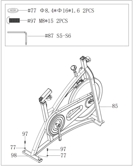
STEP 2:
Pull out the Seat Post (No. 37) from Main Frame (No. 85). Turn the Seat Post (No. 37) at 180° as left picture showed. Then re-insert Seat Post (No. 37) into the sleeve located on the Main Frame (No. 85). Adjust the Seat Post (No. 37) to the desired position and tighten with the Adjustment Knob (No. 38).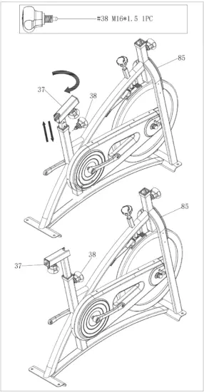
STEP 3:
Attach the Front and Rear Stabilizers (No. 73 & No. 84) to the Main Frame (No. 85) using 4 Screws (No. 76) and 4 Washers (No. 77). Tighten and secure with Allen Wrench (No. 87).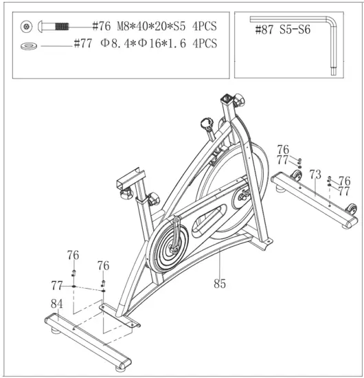
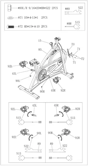
STEP 4:
WARNING! Read instructions carefully as improper assembly may cause permanent damage to your bike.
Note: The Pedals (No. 92L/R) are marked “L” and “R” for Left and Right.
Remove the 2 Nylon Nuts (No. 90L/R) located on the Pedals (No. 92L/R).
Turn the Tension Control Knob (No. 15) CLOCKWISE as tightly as you can with your hand.
Align the Left Pedal (No. 92L) with the Left Crank (No. 45L) at 90°. Turn the pedal bolt on the Left Pedal (No. 92L) COUNTER-CLOCKWISE as tightly as you can with your hand. Then, use Spanner (No. 88) to tighten and secure.
Turn the Left Nylon Nut (No. 90L) CLOCKWISE as tightly as you can with your hand. Use Spanner (No. 88) to hold the pedal bolt on the Left Pedal (No. 92L) and use Spanner (No. 89) to turn the Left Nylon Nut (No. 90L) CLOCKWISE at the same time, until it is tightened on to the Left Crank (No. 45L).
Align the Right Pedal (No. 92R) with the Right Crank (No. 45R) at 90°. Turn the pedal bolt on the Right Pedal (No. 92R) CLOCKWISE as tightly as you can with your hand. Then, use Spanner (No. 88) to tighten and secure.
Turn the Right Nylon Nut (No. 90R) COUNTER-CLOCKWISE as tightly as you can with your hand. Use Spanner (No. 88) to hold the pedal bolt on the Right Pedal (No. 92R) and use Spanner (No. 89) to turn the Right Nylon Nut (No. 90R) COUNTERCLOCKWISE at the same time, until it is tightened on to the Right Crank (No. 45R).
Remove 2 Screws (No. 72) and 2 Washers (No. 71) from the Main Frame (No. 85) using Spanner (No. 88). Attach the Water Bottle Holder (No. 70) to the Main Frame (No. 85) using the 2 Screws (No. 72) and 2 Washers (No. 71) that were removed. Tighten and secure with Spanner (No. 88).
STEP 5:
Loosen and remove the [seat slider] Adjustment Knob (No. 38). Insert Seat Slider (No. 36) into the Seat Post (No. 37). Adjust the Seat Slider (No. 36) to the desired position, re-insert and tighten Adjustment Knob (No. 38) to secure the post in place.
Secure Seat (No. 35) to the Seat Slider (No. 36) with Spanner (No. 88).
NOTE: Before you fully tighten the seat, you can adjust the front of the seat higher or lower to meet your needs.
STEP 6:
Loosen and remove the [handlebar] Adjustment Knob (No. 38). Insert Handlebar Post (No. 10) into the sleeve located on the front of the Main Frame (No. 85). Adjust the Handlebar Post (No. 10) to the desired position and reinsert and tighten the Adjustment Knob (No. 38) to secure the post in place.
Secure Handlebar (B) (No. 8) to Handlebar Post (No. 10) using 2 Bolts (No. 6) and 2 Nuts (No. 11). Tighten and secure with Spanner (No. 89).
Attach Tablet Bracket (No. 2) onto the Handlebar (B) (No. 8) with Screw (No. 83). Tighten and secure with Spanner (No. 88). Attach the Computer (No. 9) to the bracket located on the Handlebar Post (No. 10). Connect the link wire of the Computer (No. 9) to the Trunk Wire (No. 91).
The assembly is complete!
BATTERY INSTALLATION & REPLACEMENT
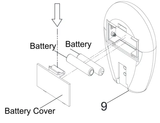
BATTERY INSTALLATION
- Take out 2 AA batteries from computer box.
- Press the buckle of battery cover on the back of the Computer (No. 9), then remove battery cover.
- Install 2 AA batteries into the battery case on the back of the Computer (No. 9). Pay attention to the battery + and – poles before installing.
- Press the buckle of battery cover, then put the battery cover back to the back of the Computer (No. 9).
The installation is complete!
BATTERY REPLACEMENT
- Press the buckle of battery cover on the back of the Computer (No. 9), then remove battery cover.
- Remove the 2 old AA batteries in the battery case and install 2 new AA batteries into the battery case on the back of the Computer (No. 9). Pay attention to the battery + and – poles before installing.
- Press the buckle of battery cover, then put the battery cover back to the back of the Computer (No. 9).
The replacement is complete!
NOTE: Always change both batteries at the same time. Do not mix battery types and do not mix old and new batteries. Dispose batteries according to your state and regional guidelines.
EXERCISE COMPUTER
SPECIFICATIONS
TIME ——————————————-00:00-99:59 MIN:SEC
SPEED —————————————-0.0-999.9 MI (Mile)/H
DISTANCE ———————————–0.00-99.99 MI (Mile)
CALORIES ———————————–0.0-999.9 KCAL
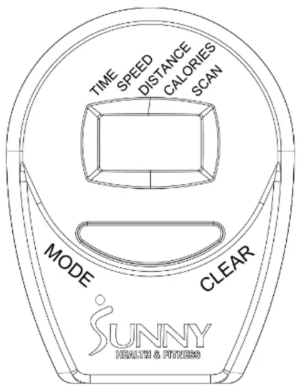
FUNCTION KEY
MODE: Press to select function (Scan, Time, Speed, Distance, Calories). Press and hold for 3 seconds to reset all values.
CLEAR: Press to reset value. This function is only available when the bike is stopped, and the computer is not in SCAN mode.
OPERATION PROCEDURES
- AUTO ON/OFF: If the bike is put into motion or the MODE button is pressed, the computer will activate and will remain active unless inactive for approximately 4 minutes. The computer power will turn off automatically.
- MODE: To select the LOCK MODE setting, press the MODE button when the pointer is on the function you wish to display, then remove your finger from the button. Once locked, only the selected function will be displayed.
FUNCTIONS
TIME: Counts the total time of an exercise from start to finish.
SPEED: Displays the current speed being obtained.
DISTANCE: Counts the total distance of an exercise from start to finish.
CALORIES: Counts the total number of calories burned during an exercise from start to finish. (The data is a rough guide which can not be used in medical treatment.)
SCAN: Automatically displays functions in the following order shown: Time, Speed, Distance, Calories (repeat).
BATTERY: This computer uses two AA ba
ADJUSTMENTS & USAGE GUIDE
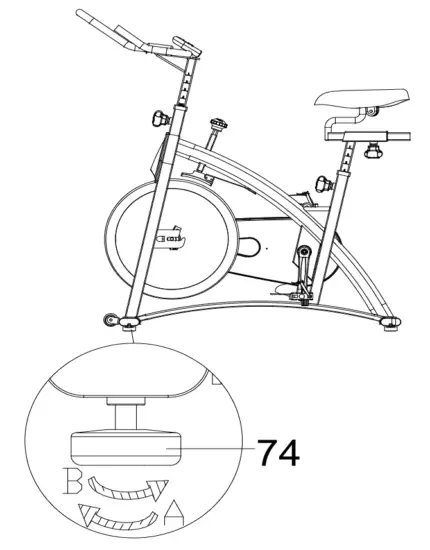 | ADJUSTING THE BALANCEIn order to achieve a smooth and comfortable ride, you must ensure that the bike is stabled and secured. If you notice that the bike is unbalanced during use, you should adjust the Foot Levelers (No. 74) located beneath the front and rear stabilizers. To do so, simply rotate the Foot Leveler (No. 74) until the bike becomes level with the floor surface. If required, repeat this process to adjust the remaining Foot Levelers (No. 74). |
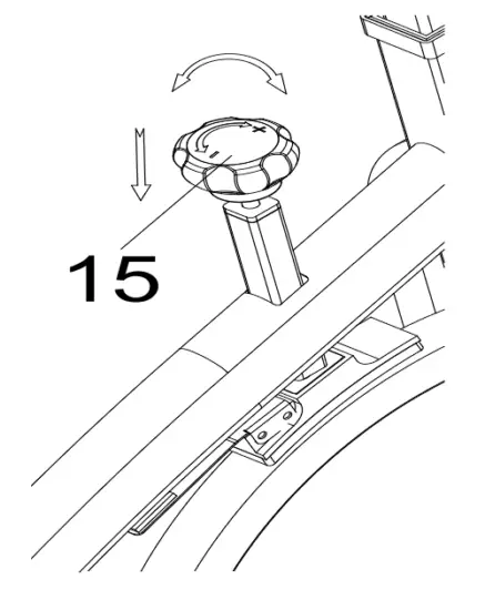 | ADJUSTING THE TENSION & EMERGENCY STOPAdjust the tension by rotating the Tension Control Knob (No. 15) clockwise to increase the level of resistance. Rotate the Tension Control Knob (No. 15) counter-clockwise to decrease the level of resistance. Push down on the Tension Control Knob (No. 15) to enforce the brake and stop the bike immediately |
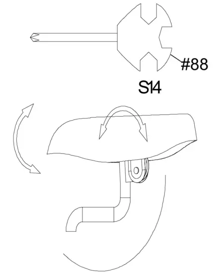 | ADJUSTING THE ANGLE OF SEATUse Spanner (No. 88) to unscrew the nut under the seat. Adjust the seat to the desired angle and reinstall the nut. Check the nut periodically to ensure that it is tight and secure. Use the Spanner (No. 88) to tighten when necessary. Note: You will need to tighten the nut on the opposite side at the same time. The use of an additional spanner is required. |
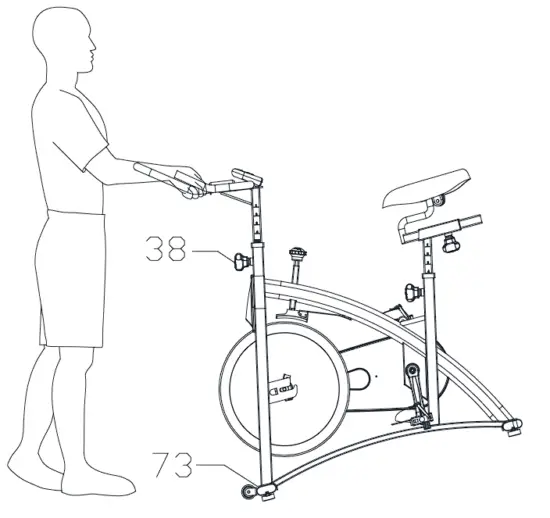 | MOVING THE BIKETo move the bike, first ensure that the handlebar is properly secured. If the handlebar is loose, tighten the Adjustment Knob (No. 38) to secure it. Next, stand at the front of the bike so that you’re directly in front of the handlebar. Firmly grasp and hold each side of the handlebar, place one foot on the Front Stabilizer (No. 73), and tilt the bike towards you until the transportation wheels on the Front Stabilizer (No. 73) touches the ground. With the transportation wheels on the ground, you can transport the bike to the desired location with ease. |
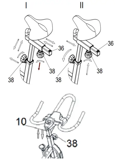 | ADJUSTING THE HEIGHTLoosen and pull out the Adjustment Knob (No. 38) to adjust the height of the seat. You may also slide the seat forward or backwards by loosening and pulling out the Adjustment Knob (No. 38) on the Seat Slider (No. 36). You may adjust the height of the handlebar by using the Adjustment Knob (No. 38). When adjusting, you will see a limit on the seat post, seat slider, and handlebar post. Do not lift the posts passed this mark. Always check the Adjustment Knob (No. 38) to ensure that it is fully secured when you finish making an adjustment. |
MAINTENANCE INSTRUCTIONS
This is general information for daily, weekly, and monthly maintenance to be performed on your bike.
DAILY MAINTENANCEAfter each exercise session, wipe down all the equipment: seat, frame, and handlebars. Pay special attention to the seat post, handlebar post, and belt/chain guard. Sweat is very corrosive and may cause problems that require parts replacement later.
| MONTHLY MAINTENANCE
|
WEEKLY MAINTENANCE
| LEATHER BRAKE PAD CARE (If applicable)
|
CONNECT WITH US
FOR Fl1TNESS ARTICLES, VIDEOS & WORKOUTS