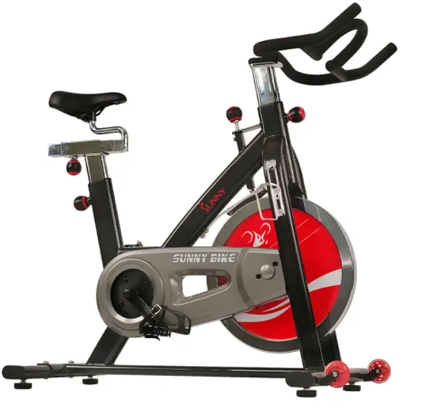
SUNNY Belt Drive Indoor Cycling Bike
IMPORTANT: Read all instructions carefully before using this product. Retain owner’s manual for future reference. For customer service, please contact: [email protected]
IMPORTANT SAFETY INFORMATION
We thank you for choosing our product. To ensure your safety and health, please use this equipment correctly. It is important to read this entire manual before assembling and using the equipment. Safe and effective use can only be assured if the equipment is assembled, maintained, and used properly. It is your responsibility to ensure that all users of the equipment are informed of all warnings and precautions.
- Before starting any exercise program you should consult your physician to determine if you have any medical or physical conditions that could put your health and safety at risk or prevent you from using the equipment properly. Your physician’s advice is essential if you are taking any medication that may affect your heart rate, blood pressure, or cholesterol level.
- Be aware of your body’s signals. Incorrect or excessive exercise can damage your health. Stop exercising if you experience any of the following symptoms: pain, tightness in your chest, irregular heartbeat, shortness of breath, lightheadedness, dizziness, or feelings of nausea. If you do experience any of these conditions, you should consult your physician before continuing with your exercise program.
- Keep children and pets away from the equipment. The equipment is designed for adult use only.
- Use the equipment on a solid, flat level surface with a protective cover for your floor or carpet. To ensure safety, the equipment should have at least 2 feet of free space all around it.
- Ensure that all nuts and bolts are securely tightened before using the equipment. The safety of the equipment can only be maintained if it is regularly examined for damage and/or wear and tear.
- It is recommended that you lubricate all moving parts on a monthly basis.
- Always use the equipment as indicated. If you find any defective components while assembling or checking the equipment, or if you hear any unusual noises coming from the equipment during exercise, stop using the equipment immediately and don’t use the equipment until the problem has been rectified.
- Wear suitable clothing while using the equipment. Avoid wearing loose clothing that may become entangled in the equipment.
- Do not place fingers or objects into the moving parts of the equipment.
- The maximum weight capacity of this unit is 265 pounds.
- This equipment is not suitable for therapeutic use.
- Move with caution when lifting and moving the equipment. Always use proper lifting technique and seek assistance if necessary.
- Your product is intended for use in cool, dry conditions. You should avoid storage in extreme cold, hot, or damp areas as this may lead to corrosion and other related problems.
- This equipment is designed for indoor use only! It is not intended for commercial use!
Parts List
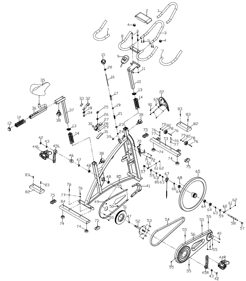
| No. | Description | Qty |
| 1 | Foam (A) Φ23*3*550 | 1 |
| 2 | Handlebar cover | 1 |
| 3 | Handlebar (A) | 1 |
| 4 | End cap Φ25*16 | 2 |
| 5 | Screw M6*16*S5 | 4 |
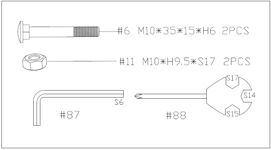
| 6 | Bolt M10*35*15*H6 | 2 |
| 7 | Foam grip Φ23*3*480 | 2 |
| 8 | Handlebar (B) | 1 |
| 9 | Computer | 1 |
| 10 | Handlebar post | 1 |
| 11 | Nut M10*H9.5*S17 | 2 |
| 12 | End cap Φ22*16 | 1 |
| 13 | End cap F30*30*16 | 3 |
| 14 | Bushing F38*F30*153.3 | 3 |
| 15 | Tension knob Φ58*44*M8*18 | 1 |
| 16 | Brake rod Φ10*210*M8*15*M6*7*M10*95 | 1 |
| 17 | Bushing 20*20*74 | 1 |
| 18 | Washer d6*Φ12*1.2 | 2 |
| 19 | Square nut 16*16*25*M10 | 1 |
| 20 | Bolt M8*H5.5*S14 | 1 |
| 21 | Spring Φ2.0*Φ15*54*N12 | 1 |
| 22 | Decorate cover 195*161*31 | 1 |
| 23 | Nut M10*H5.5*S17 | 1 |
| 24 | Nut M6*H14*S10 | 1 |
| 25 | Brake stopper 35*24*2 | 1 |
| 26 | Spring Φ2*Φ24*Φ13*15*N5 | 1 |
| 27 | Brake block 110*27*30 | 1 |
| 28 | Washer d5*Φ10*1 | 2 |
| 29 | Nut M5*H5.5*S10 | 2 |
| 30 | Screw M5*30*Φ8 | 2 |
| 31 | Woolen felt 110*30*8 | 1 |
| 32 | Spring piece t2*59*185 | 1 |
| 33 | Rubber mat 44*25*3 | 1 |
| 34 | Bolt M6*12*S10 | 2 |
| 35 | Saddle 98-2 | 1 |
| 36 | Seat Slider | 1 |
| 37 | Saddle post | 1 |
| 38 | Adjustment knob Φ61*M16*1.5*18*Φ8 | 3 |
| 39 | Grommet Φ12*11*Φ3 | 1 |
| 40 | Screw M6*10*Φ12 | 2 |
| 41 | Front cover 157*152*38.5 HIPS | 1 |
| 42 | Crank cap Φ25*7 | 2 |
| 43 | Nut M10*1.25 *H7.5*S14 | 2 |
| 44L/R | Pedal YH-28X 9/16″ | 2 |
| 45L/R | Crank arm 170 “L/R”9/16 | 2 |
| No. | Description | Qty |
| 46 | Cover for middle axle Φ50*Φ32*33 | 1 |
| 47 | Circlip d17 | 2 |
| 48 | Bearing 6203-2RS | 2 |
| 49 | Inner chain cover 504*259*23 | 1 |
| 50 | Screw ST4.2*16*Φ8 | 3 |
| 51 | Belt wheel Φ204*20*5PK | 1 |
| 52 | Middle axle | 1 |
| 53 | Screw M10*16*S6 | 4 |
| 54 | Belt 5PK520 | 1 |
| 55 | Screw ST4.2*13*Φ8 | 9 |
| 56 | Outer chain cover 648*264*45 | 1 |
| 57 | Nut M12*1*H19.5*S19 | 2 |
| 58 | Inertia axle Φ15*165*72*M12*1*33.5 | 1 |
| 59 | Spacer Φ22*Φ12.5*6 | 2 |
| 60 | Adjusting screw M6*45*Φ12*4 | 2 |
| 61 | Nut M6*H5*S10 | 2 |
| 62 | Nut M6*H6*S10 | 2 |
| 63 | Nut M12*1*H6*S19 | 3 |
| 64 | Bearing 6202-2RS C﹠U | 3 |
| 65 | Inertial wheel 18*Φ460*75*30*Φ55*42*PK | 1 |
| 66 | Spacer Φ18*Φ12.2*4 | 1 |
| 67 | Inductor | 1 |
| 68 | Magnet | 1 |
| 69 | Washer d5*Φ13*1.0 | 4 |
| 70 | Water bottle holder | 1 |
| 71 | Washer d5*Φ13*1 | 2 |
| 72 | Screw M5*16*Φ10 | 2 |
| 73 | Front Stabilizer | 1 |
| 74 | Foot leveler Φ43*14*M8*25 | 4 |
| 75 | End cap PT69*29*19 | 4 |
| 76 | Screw M8*40*20*S6 | 6 |
| 77 | Washer d8*Φ16*1.5 | 4 |
| 78 | Roll wheel Φ42*18*ф8*22 | 2 |
| 79 | Nut M8*H7.5*S13 | 2 |
| 80 | Washer d8*Φ16*1.5 | 2 |
| 81 | Screw ST4.8*10*Φ8 | 4 |
| 82 | Shipping tubes | 2 |
| 83 | Screw M8*16*S6 | 4 |
| 84 | Rear stabilizer | 1 |
| 85 | Main frame | 1 |
| 86 | Spacer Φ18*Φ12.2*11.5 | 1 |
| 87 | Allen wrench S6 | 1 |
| 88 | Spanner S14-15-17 | 1 |
HARDWARE PACKAGE
ASSEMBLY INSTRUCTIONS
STEP 1: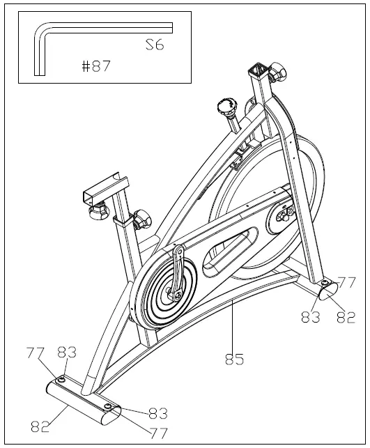 Unscrew the Screws (No. 83) with Allen Wrench (No. 87) and remove the Washers (No. 77) and Shipping Tubes (No. 82).
You may discard these parts or save them in case you’d like to repackage the item in the future.
[Screws (No. 83), Washers (No. 77), and Shipping Tubes (No. 82)]
STEP 2: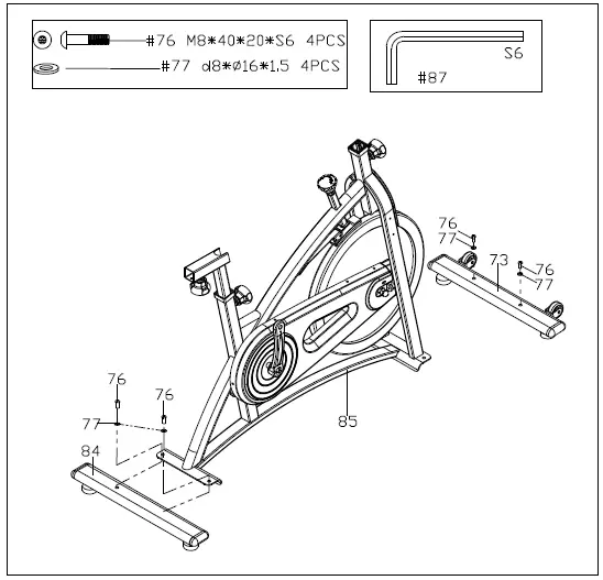 Attach the Front and Rear Stabilizers (No. 73 & No. 84) to the Main Frame (No. 85) using 4 Screws (No. 76) and 4 Washers (No. 77). Tighten and secure with Allen Wrench (No. 87).
STEP 3: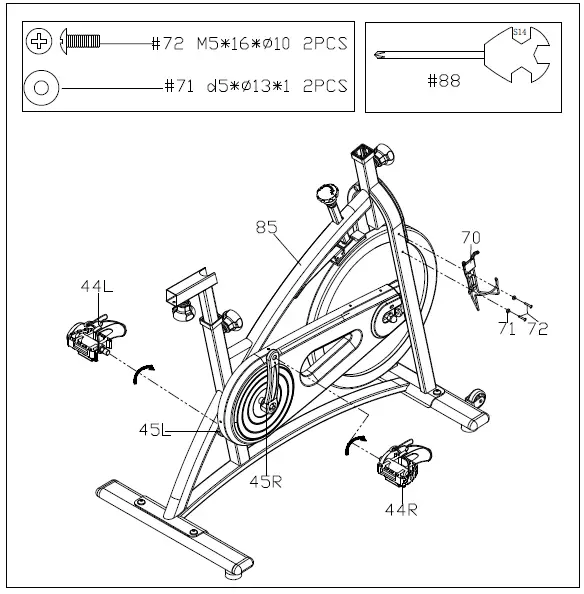 Before you begin, immobilize the crank arms by turning the tension knob all the way to the right.
Left Pedal: Align the Left Pedal (No. 44L) with the Left Crank Arm (No. 45L) at 90 degrees. Gently insert the pedal into the crank arm, turn the pedal counter-clockwise as tightly as you can with your hand. Tighten and secure with Spanner (No. 88).
Right Pedal: Align the Right Pedal (No. 44R) with the Right Crank Arm (No. 45R) at 90 degrees. Gently insert the pedal into the crank arm, turn the pedal clockwise as tightly as you can with your hand. Tighten and secure with Spanner (No. 88).
Connect the Water Bottle Holder (No. 70) to the Main Frame (No. 85) using 2 Screws (No. 72) and 2 Washers (No. 71). Tighten and secure with Spanner (No. 88).
STEP 4: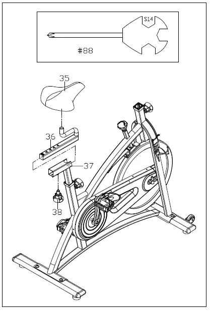
Loosen and remove the [seat slider] Adjustment Knob (No. 38). Insert Seat Slider (No. 36) into the Saddle Post (No. 37). Adjust the Seat Slider (No. 36) to the desired position and reinsert and tighten Adjustment Knob (No. 38) to secure the post in place.
Secure Saddle (No. 35) to the Seat Slider (No. 36).
NOTE: Before you fully tighten the saddle, you can adjust the front of the saddle higher or lower to meet your needs.
STEP 5: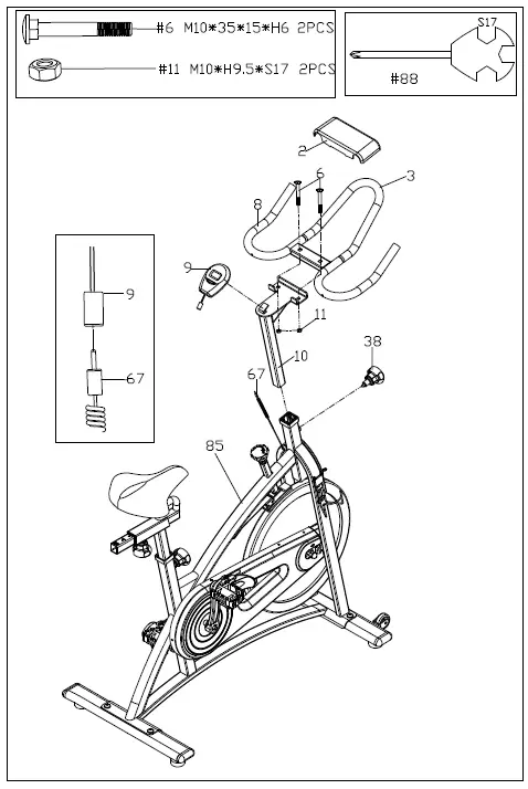 Loosen and remove the [handlebar] Adjustment Knob (No. 38). Insert Handlebar Post (No. 10) into the sleeve located on the front of the Main Frame (No. 85). Adjust the Handlebar Post (No. 10) to the desired position and reinsert and tighten the Adjustment Knob (No. 38) to secure the post in place.
Secure Handlebar B (No. 8) to Handlebar Post (No. 10) using 2 Bolts (No. 6) and 2 Nuts (No. 11). Tighten and secure with Spanner (No. 88).
Attach Handlebar Cover (No. 2) to the middle of the Handlebar B (No. 8) as shown above.
Attach the Computer (No. 9) to the bracket located on the Handlebar Post (No. 10). Connect the link wire of the Computer (No. 9) to the Inductor (No. 67).
The assembly is complete!
EXERCISE COMPUTER
SPECIFICATIONS:
TIME——————————————- 00:00-99:59 MIN:SEC
SPEED—————————————- 0.0-999.9 KM/H or ML/H
DISTANCE———————————– 0.00-99.99 KM or ML
CALORIES———————————– 0.0-999.9 KCAL
FUNCTION KEY:
MODE: Press to select function (Time, Speed, Distance, Calories)
OPERATION PROCEDURES:
- AUTO ON/OFF: If the belt is put into motion or the mode button is pressed, the computer will activate and will remain active unless there is without a signal for approximately 4 minutes. The monitor power will turn off automatically.
- MODE: To select the LOCK MODE setting press the MODE button when the pointer on the function you wish is displayed release your finger off the button. Once locked, only the selected function will be displayed.
FUNCTIONS:
- TIME: Counts the total time of an exercise from start to finish.
- SPEED: Displays the current speed being obtained.
- DISTANCE: Counts the total distance of an exercise from start to finish.
- CALORIES: Counts the total amount of calories burned during an exercise start to finish.
- SCAN: Automatically displays functions in the following order shown: time, speed, distance, calories (repeat).
- Battery: This monitor uses two AA batteries. If the display appears improper or becomes difficult to read please install new batteries before attempting to contact.
ADJUSTMENTS & USAGE GUIDE
ADJUSTING THE BALANCE
In order to achieve a smooth and comfortable ride, you must ensure that the stability of the bike is secured. If you notice that the bike is unbalanced during use, you should adjust the foot levelers located beneath the front and rear stabilizers. To do so, simply rotate the Foot Leveler (No. 74) until the bike becomes level with the floor surface.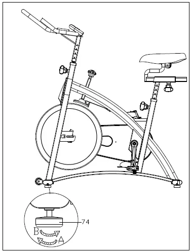
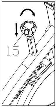
ADJUSTING THE TENSION & EMERGENCY STOP
Adjust the tension by rotating the Tension Knob (No. 15) clockwise to increase the level of resistance. Rotate the knob counter-clockwise to decrease the level of resistance. Push down on Tension Knob (No. 15) to enforce the brake and stop the bike immediately.
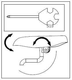
ADJUSTING THE ANGLE OF SEAT
Use Spanner (No. 88) to unscrew the nut under the saddle. Adjust the saddle to the desired angle and reinstall the nut. Check the nut periodically to ensure that it is tight and secure. Use the Spanner (No. 88) to tighten when necessary.
MOVING THE BIKE
To move the bike, first ensure that the handlebar is properly secured. If the handlebar is loose, tighten the Adjustment Knob (No. 38) to secure it. Next, stand at the front of the bike so that you’re directly in front of the handlebar. Firmly grasp and hold each side of the handlebar, place one foot on the front stabilizer and tilt the bike towards you until the transportation wheels on the front stabilizer touch the ground. With the wheels on the ground, you can transport the bike to the desired
location with ease.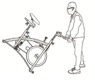
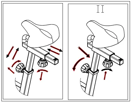
ADJUSTING THE HEIGHT
Loosen and pull out the [seat height] Adjustment Knob (No. 38) to adjust the height of the saddle. You may also slide the seat forward or backwards by loosening and pulling out the [seat] Adjustment Knob (No. 38) on the Seat Slider (No. 36). You may adjust the height of the handlebar by using the [handlebar] Adjustment Knob (No. 38). When making adjustments, you will see a limit on the saddle post, seat slider and handlebar post. Do NOT lift the posts passed this mark. Always check the Adjustment Knobs (No. 36) to ensure that they are fully secure when you finish making an adjustment.