PDU for VFI ICR IoT 6-10kVA
![]()
Installation and user manual
Service and support:
Call your local service representative
SAFETY INSTRUCTIONS
SAVE THESE INSTRUCTIONS. This manual contains important instructions that should be followed during installation and maintenance of the MBP.
The MBP models that are covered in this manual are intended for installation in an environment within 0 to 50°C, free of conductive contaminant.
Special symbols
 RISK OF ELECTRIC SHOCK – Observe the warning associated with the risk of electric shock symbol.
 Important instructions that must always be followed.
 EU separate collection mark for waste electrical and electronic equipment (WEEE). Indicates that the item must not be disposed of to the normal household waste but be separately collected and recycled.
 Information, advice, help.
 Refer to the user manual.
Safety of persons
- Terminal blocks may be energized even if the system is disconnected from the AC power source.
- Dangerous voltage levels are present within the system. It should be opened exclusively by qualified service personnel.
- The system must be properly grounded, always connect the earth wire first.
Product safety
- The MBP connection instructions and operation described in the manual must be followed in the indicated order.
- CAUTION – To reduce the risk of fire, the unit connects only to a circuit provided with branch circuit overcurrent protection for:
63A rating, for 6kVA models,
80A rating, for 10kVA models
The upstream circuit breaker for Normal AC/Bypass AC must be easily accessible. The unit can be disconnected from AC power source by opening this circuit breaker. - Disconnection and overcurrent protection devices shall be provided by others for permanently connected AC input (Normal AC/Bypass AC) and AC output circuits.
- Check that the indications on the rating label correspond with your AC powered system and the actual electrical consumption of all the equipment to be connected to the system.
- For PLUGGABLE EQUIPMENT, the socket-outlet shall be installed near the equipment and shall be easily accessible
- Never install the system near liquids or in an excessively damp environment.
- Never let a foreign body penetrate inside the system.
- Never block the ventilation grates of the system.
- Never expose the system to direct sunlight or source of heat.
- If the system must be stored prior to installation, storage must be in a dry place.
- The admissible storage temperature range is -25°C to +60°C.
Special precautions
- This MBP is designed to work with UPS. All repairs and service should be performed by A UTHORIZED SERVICE PERSONNEL ONLY.
- There are NO USER SERVICEABLE PARTS inside the MBP.
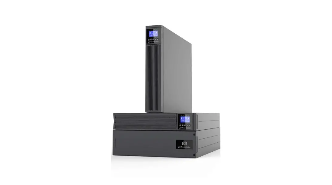
1 Introduction
Thank you for selecting MBP(Maintenance Bypass modular) to protect your electrical equipment.
The MBP allows service person to service or replace the UPS without interrupting the connected loads. Besides, it also allow you apply for below extension used
- Terminal block connection design enable the MBP connect to other type UPS.
- Rotatable `rail kit’ design for easy service operation in a rack cabinet.
- Flexible position installation.
We recommend that you take the time to read this manual to take full advantage of the many features of your MBP.
1.1 Environmental protection
Products are developed according to an eco-design approach.
Substances
This product does not contain CFCs, HCFCs or asbestos.
Packing
To improve waste treatment and facilitate recycling, separate the various packing components.
- The cardboard we use comprises over 50% of recycled cardboard.
- Sacks and bags are made of polyethylene.
- Packing materials are recyclable
Follow all local regulations for the disposal of packing materials.
Product
The product is mainly made up of recyclable materials.
Dismantling and destruction must take place in compliance with all local regulations concerning waste. At the end of its service life, the product must be transported to recycling centers, re-use and treatment facilities for waste electrical and electronic equipment (WEEE).
2 Product Overview
2.1 Model list
![]()
- The weight in this table is reference only, please see the labels on the carton for details.
- Dimension `D’ is chassis only.
| Product | Net Weights (kg) | Dimensions (mm) W x H x D | |
| PDU for | VFI ICR IoT 6-10kVA 1-1 | 2.4 | |
| PDU for | VFI ICRS IoT 10kVA 3-1 | 2.8 |
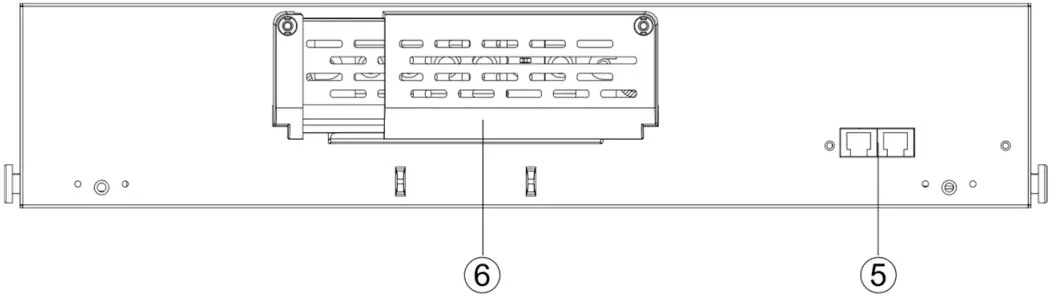
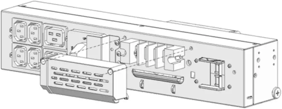
2.2 Presentation
MBP(1-1)
1. Output socket group 1 (no programmable)
2. Output socket group 2 (programmable)
3. Output Breaker (Optional, default is no)
4. Maintenance bypass switch
5. Input /Output terminal(Connected to power and load)
6. Input switch
7. Input /Output terminal (Connected to UPS)
8. RJ45 port(including EBM Detect and RT model MBP COMM)
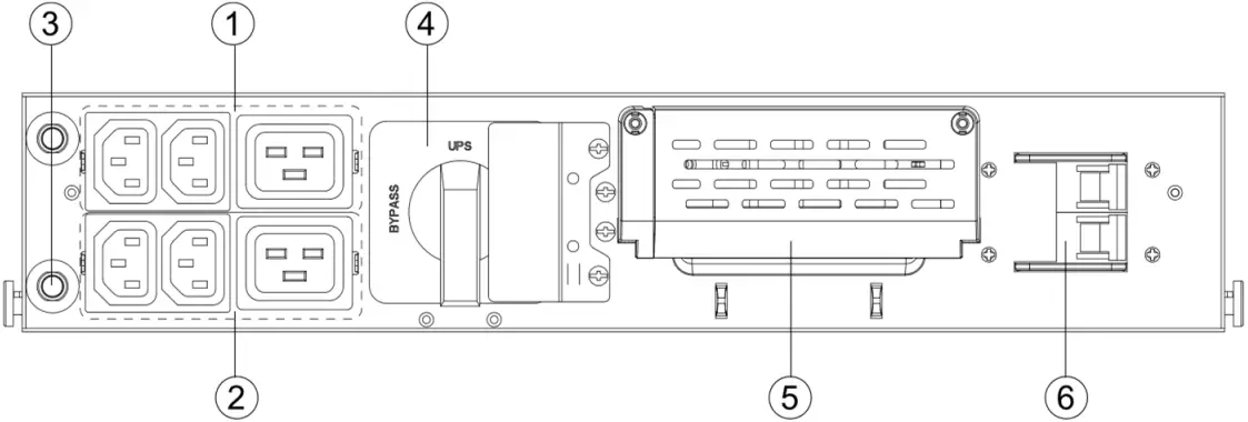
Front Panel
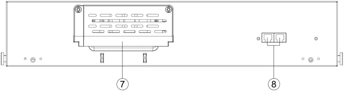
Rear Panel
MBP(3-1)
1. Output socket group (programmable)
2. Maintenance bypass switch
3. Input /Output terminal (Connected to power and load)
4. Input switch
5. RJ45 port(including EBM Detect and RT model MBP COMM)
6. Input /Output terminal (Connected to UPS)
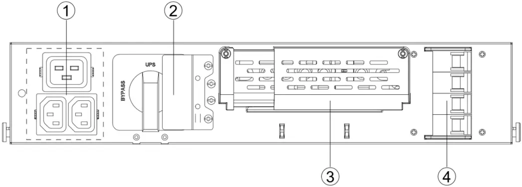 Front Panel
 Rear Panel
3 Installation
The system may be installed only by qualified electricians in accordance with applicable safety regulations.
3.1 Unpacking and Inspecting
Unpacking the unit in a low-temperature environment may cause condensation occurred in and on the cabinet. Do not install the unit until the inside and outside of the unit are absolutely dry (hazard of electric shock).
If any equipment has been damaged during shipment, keep the shipping cartons and packing materials for the carrier or place of purchase and file a claim for shipping damage. If you discover damage after acceptance, file a claim for concealed damage.
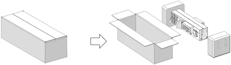
Note
Discard or recycle the packaging in a responsible manner, or store it for future use.
![]() Packing materials must be disposed in compliance with all local regulations concerning waste. Recycling symbols are printed on the packing materials to facilitate sorting.
Packing materials must be disposed in compliance with all local regulations concerning waste. Recycling symbols are printed on the packing materials to facilitate sorting.
3.2 Checking the accessory kit
Verify that the following additional items are included with the unit:
| MBP(1-1) | MBP(3-1) | |
| Cables for UPS Input / Output | √ | √ |
| MBP detection cable | √ | √ |
| Copper bus-bar | √ | |
| Cable locker for Output socket | √ | √ |
| Ear bracket(For tower install) | √ | √ |
| Rail kit(For rack install) | √ | √ |
| User manual | √ | √ |
Note:√— Standard configuration; O—Option, default is Not configured
3.3 Mechanical Installation
![]() This model support 2 installation modes: Rack installation and Tower installation.
This model support 2 installation modes: Rack installation and Tower installation.
It is recommended to connect ‘cables for UPS Input / Output’ and ‘MBP detection cable’ to the MBP before installing.
1. Remove the cover of terminal blocks and connect ‘cables for UPS Input/ Output’ to terminal blocks refer to the indication on rear panel.
MBP(1-1):
MBP(3-1):
![]() For cables well fixed, it is recommended to tie these cables to the convex of rear-panel.
For cables well fixed, it is recommended to tie these cables to the convex of rear-panel.
2. Install back the cover of terminal blocks and insert ‘MBP detection cable’.
3.3.1 Tower installation :
Assume that you already purchased our UPS and fix the UPS in tower position.
1. Our UPS provided 2 positions to install the MBP, needed additional space is as below.
It is recommended to select ‘Left position’ as your final installation according to the configured length of ‘cables for UPS Input / Output’ and ‘MBP detection cable’.
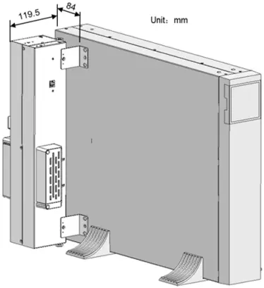
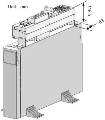
Left position Top position
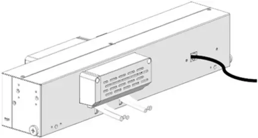
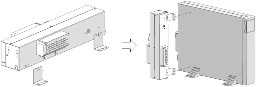
2. Install ‘Ear bracket’ to MBP, then assemble MBP to UPS by M4 screws. Below pictures are examples of ‘Left position’ installation.
3.3.2 Rack position installation :
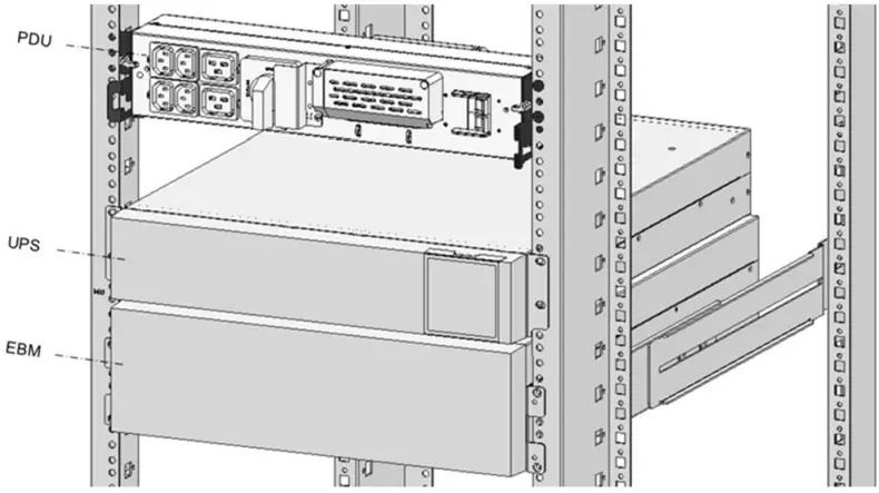
This MBP is flexible position installing in a rack cabinet as below.
It is recommended to select ‘Position 1’ as your final installation according to the configured length of ‘cables for UPS Input / Output’ and ‘MBP detection cable’.
• Position 1(Rear of rack)
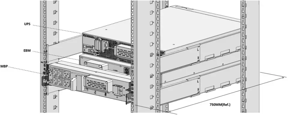
• Position 2(Front of rack)
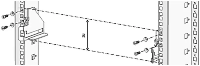
1. Install ‘Rail kit’ to rack cabinet by M5 screws and washers.
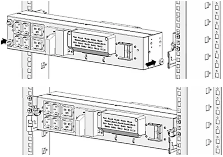
2. Slide MBP into ‘rail kit’ and make sure lock MBP by the 2 clips.
3.4 Power cables connection
This chapter introduces how to connect MBP to UPS, and connect AC IN/OUT cable to MBP.
3.4.1 Wiring for MBP connecting to UPS
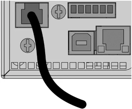
![]() Before power cables connected, Insert ‘MBP detection cable’ to the port ‘MBP/BATT.
Before power cables connected, Insert ‘MBP detection cable’ to the port ‘MBP/BATT.
DECTECT’ on the rear of UPS.
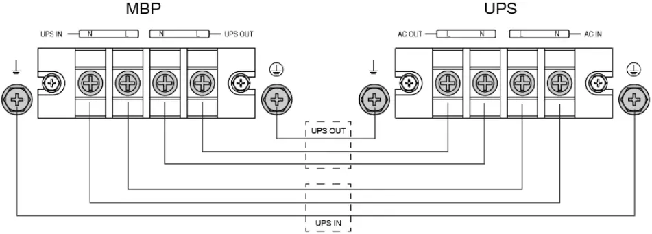
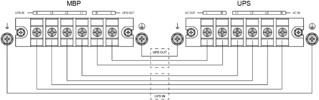
Connect ‘cables for UPS Input/ Output’ to UPS terminal blocks refer to below indication.
1-1 model:
3-1 model:
3.4.2 Wiring for AC Cable (AC source to MBP)
Please refer to UPS user manual for upstream protection and downstream switch.
Recommended cable minimum cross-sectional area.
| Model | MBP 1-1 | MBP 3-1 | |
| With RT 6K(S) 1-1 | With RT 10K(S) 1-1 | With RT 10K(S) 3-1 | |
| Protective earthing conductor | 10mm2 | 10mm2 | 10mm2 |
| Input L, N cable | 6mm2 | 10mm2 | 10mm2 |
| Output L, N cable | 6mm2 | 10mm2 | 10mm2 |
The length of the output cable is recommended not to exceed 10 meters, otherwise, it may cause radio interference. If a length of output cable over 10 meters requests, please contact distributors/agents for details.
![]() High leakage current:
High leakage current:
Earth connection essential before connecting supply.
![]() This type of connection must be carried out by qualified electrical personnel.
This type of connection must be carried out by qualified electrical personnel.
Before carrying out any connection, check that the upstream protection devices
(Normal AC source) are open “O” (Off).
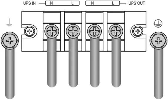
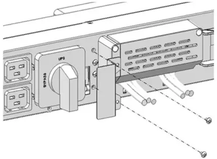
1. Remove the cover of terminal block.
2. Connect the AC cable to terminal blocks refer to the indication on panel.
MBP(1-1):
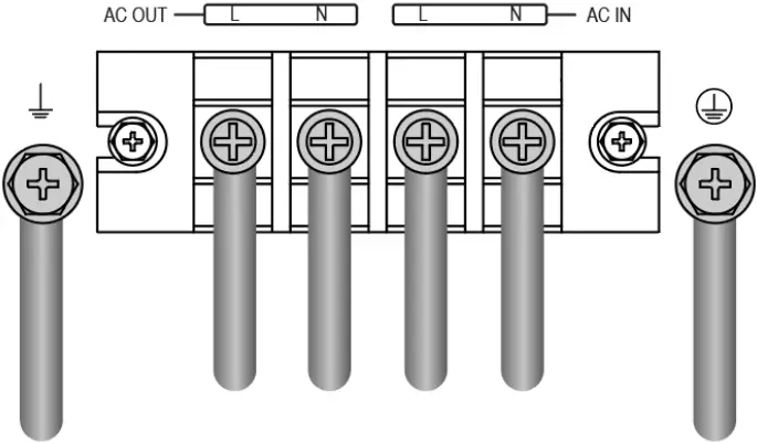
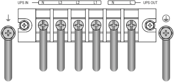
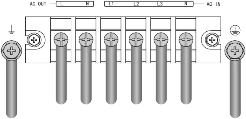
MBP(3-1):
This model support 2 mode setting as below, default is setting with 3-1 mode.
1-1 mode
Short ‘MBP input terminal L1/L2/L3’ with ‘busbar’, then connect AC cable
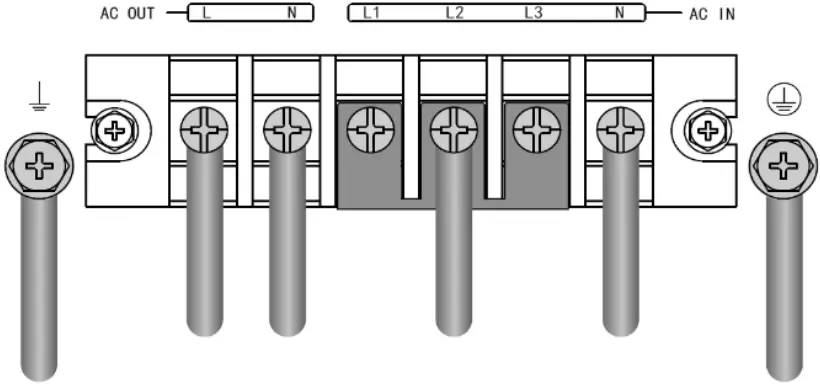
3-1 mode
![]() For cables well fixed, it is recommended to tie these cables to the convex of rear-panel.
For cables well fixed, it is recommended to tie these cables to the convex of rear-panel.
3. Install back the cover of terminal block.
4 Service operation
4.1 How to switch system to BYPASS mode
![]() Please make sure the UPS is turned to bypass mode before rotating the maintenance switch to bypass position.
Please make sure the UPS is turned to bypass mode before rotating the maintenance switch to bypass position.
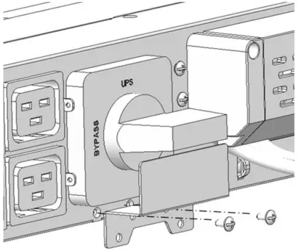
1. Remove the ‘Maintenance switch cover’, the UPS will turn to bypass mode automatically.
2. Rotate the maintenance switch to ‘’BYPASS’ position.
Note:
![]() For an unconscious operation, it is recommended to install back the ‘Maintenance switch cover’ as above to prevent ‘BYPASS’ switch back to ‘UPS-mode’.
For an unconscious operation, it is recommended to install back the ‘Maintenance switch cover’ as above to prevent ‘BYPASS’ switch back to ‘UPS-mode’.
3. Turn the MBP ‘input switch’ to ‘OFF’ position.
4. After these operations, the MBP will power the load directly via maintenance switch.
4.2 How to disconnect cables between MBP and UPS
This is to disconnect ‘cables for UPS Input / Output’ and ‘MBP detection cable’.
The pictures as below are examples of ‘Rack position’ only.
1. Unlock the clips and pull out MBP from its position smoothly, then rotate the MBP as below.
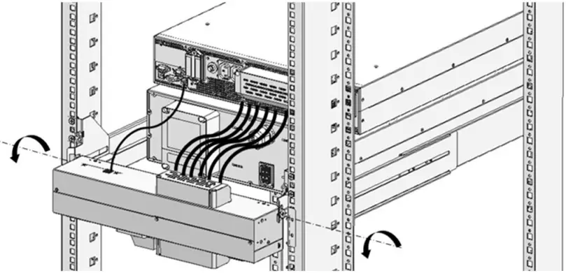
2. Disconnecting ‘cables for UPS Input / Output’ and ‘MBP detection cable’ as well as other cables connected on UPS.
3. Remove out the UPS for service or replacement.
![]() Don’t let the MBP suffer any strong stress during rotation position.
Don’t let the MBP suffer any strong stress during rotation position.
4.3 How to switch system to NORMAL mode
Clarify your UPS is already complete service or replacement installation.
1. Connect ‘cables for UPS Input/ Output’ and ‘MBP detection cable’ to UPS terminal —refer to chapter 3.4
2. Turn the MBP ‘Input switch’ to ‘ON’ position. The UPS will turn to bypass mode. If the UPS doesn’t turn to bypass mode automatically, please turn to bypass mode manually.
3. Rotate the maintenance switch to ‘UPS’ position, install back the ‘maintenance switch cover’ to its normal position.
4. Press the button on UPS LCD panel, the UPS will turn to line mode.
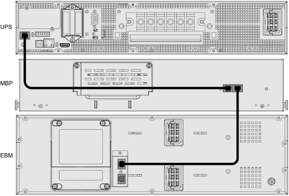
4.4 How to detect the EBM to this system
This is to connect the ‘configured EBM’ to a system (UPS+MBP) with ‘EBM detection cable’ as below.
5 Specifications
1. Electrical input—refer to the UPS input specification.
2. Electrical output—refer to the UPS output specification.
| Output socket group | Normal output | 10A & 16A |
| Programmable output | 10A & 16A |
Outlet socket group (Programmable) can be set on the LCD or by sending command; it could be sent between “always on” and “auto off-on”, and “always on” by default.
Once it is set as “auto off-on” that output power will turn off when battery capacity below 50% in battery mode, and outlet socket group (Programmable) will turn on again when charger begins to work.
3. Environment
| Operating temperature | 0~40℃ full load 40~50℃ derating to 50% 0~35℃ IEC socket 16A 35~40℃ IEC socket 10A |
| Storage temperature | -25 to 60°C |
| Transit temperature | -25 to 55°C |
| Relative humidity | 0 to 95% no condensing |
| Operating altitude | <3000m (Derating use above 1km, the load should de-rating 1% every up 100m) |
4. Criterion
| Safety | IEC/EN 62040-1 |
| EMC | IEC/EN 62040-2, C3 |


