
![]()
User’s Manual
SR250HI Series – 250W DC UPS
No-Break™
DC UPS
SR250HI Series 250W DC UPS
| STANDARD FEATURES | OPTIONAL FEATURES | ||
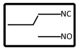 | 3 Relay Alarms-Form C |  | Comms: • RS232 • RS485 • Modbus RTU • SNMP V1 & Webpages |
 | Float Charger –Lead Acid Batteries |  | Customizable Digital I/O |
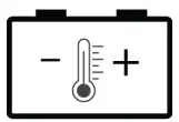 | Temperature Sensor on 1.7m lead with adhesive pad: -4mV / °C /cell ±10% | 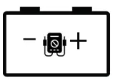 | BCT: Battery Condition Test. |
 | ELVD : Electronic low voltage disconnect | 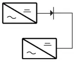 | N+1 Redundancy |
SAFETY
The user is responsible for ensuring that input and output wiring segregation complies with local standards and that in the use of the equipment, access is confined to operators and service personnel. A low resistance earth connection is essential to ensure safety and additionally, satisfactory EMI suppression (see below).
HAZARDOUS VOLTAGES EXIST WITHIN A POWER SUPPLY ENCLOSURE AND ANY REPAIRS MUST BE CARRIED OUT BY A QUALIFIED SERVICEPERSON.
Electrical Strength Tests
Components within the power supply responsible for providing the safety barrier between input and output are constructed to provide electrical isolation as required by the relevant standard. However EMI filtering components could be damaged as result of excessively long high voltage tests between input, output and ground. Please contact our technicians for advice regarding electric strength tests.
Earth Leakage
Where fitted, EMC suppression circuits cause earth leakage currents which may be to a maximum of 3.5mA.
Ventilation
High operating temperature is a major cause of power supply failures, for example, a 10°C rise in the operating temperature of a component will halve its expected life. Therefore always ensure that there is adequate ventilation for the equipment. Batteries in particular suffer shortened lifetimes if subjected to high ambient temperatures.
Water / Dust
Every effort must be made in the installation to minimise the risk of ingress of water or dust. Water will almost always cause instant failure. The effects of dust are slower in causing failure of electronic equipment but all electrical equipment should be cleaned free of any dust accumulation at regular intervals.
Electromagnetic Interference (EMI)
Switching power supplies and converters inherently generate electrical noise. All wiring should be as short as practicable and segregated from all equipment wiring which is sensitive to EMI. Residual noise can be reduced by looping DC wiring through ferrite cores (sleeves). These are most effective as close to the power supply as possible and as many turns of the wire taken through the core (+ and – in the same direction) as the core will accommodate.
External fuse protection
Fuses or circuit breakers must be used in all battery circuits to protect against short circuits. External fuses should be used for power supplies/ chargers even though they are usually internally protected.
Connection polarity
It is critical to check the polarity carefully when connecting DC devices even with models which have non-destructive reverse polarity protection.
Glossary of terms used in our user manuals
| PSU = power supply unit ELVD = electronic low voltage disconnect SNMP = Simple Network Management Protocol | BCT = battery condition test RPP = reverse polarity protection EMC = Electromagnetic compatibility | ECB = electronic circuit breaker EMI = electromagnetic interference DOD = depth of discharge |
INTRODUCTION:
The No-Break ™DC SR250Hi switch mode power supply is designed to provide DC power to lead acid batteries for critical back up applications.No-Break ™ DC UPS systems maximise the integrity of standby battery installations, whilst optimising the life and availability of back up batteries.
SR250HI Series – SYSTEM BLOCK DIAGRAM
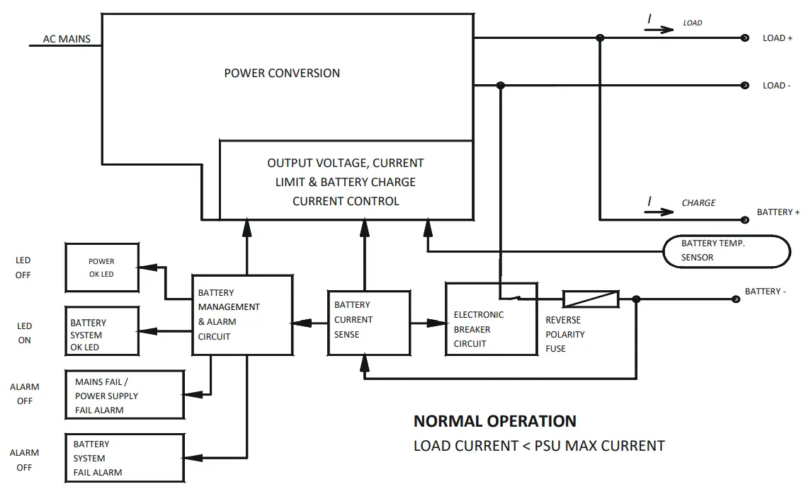
OPERATION OF ELECTRONIC CIRCUIT BREAKER (ECB) FOR PROTECTION OF BATTERY CIRCUIT & BATTERY
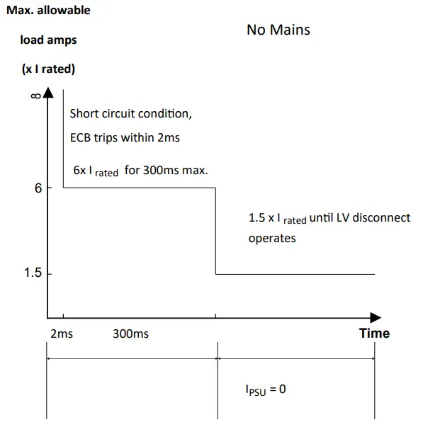
The ECB will operate on overcurrent as above & is also activated for the low voltage disconnect function on mains fail (no input power). It will reset when input power is restored, or can be manually reset by briefly shorting the BAT- and LOAD- terminals together when there is no input power.
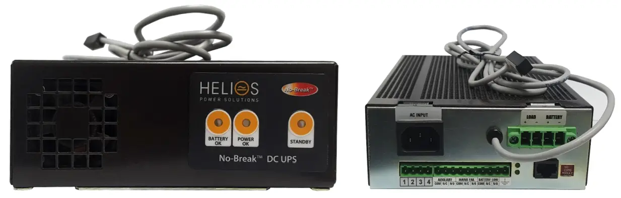
BACK & FRONT PANEL LAYOUT
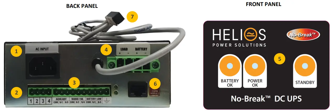
- AC INPUT IEC60320 – C13 10A
- Digital Inputs (pins 1,2)/ Input or Output (pin 3)/ Return (pin 4) I/O terminals are customizable and if used, the product will have a unique code.
- ALARMS RELAY FORM C
AUX : Activated by BCT ( Battery Condition Test)
POWER (Mains Fail):
• Loss of mains input power. This alarm has 30 seconds delay before activation upon mains failure.
• PSU fails
BATTERY:
• Battery Low: 1.8V/cell (for 2V cells) – operates only when no mains power present.
• Battery Missing or fault in battery circuit wiring (alarm does not activate for up to battery detection interval time.
• BCT fail - LOAD & BATTERY CONNECTION
- Front Panel LEDS ( For full list of LED flash codes please refer to the next page)
Battery OK: LED on: Battery present and above V batl
Power OK: LED on: Charger output present. LED off: no mains input or charger in standby mode
Standby: LED on: Charger in standby mode ( no output from charger) - Comms Port (if installed) , for models with communications please refer to
• RS232 (ASCII) https://www.heliosps.com/sr-series-downloads/#rs232-rs485-commands-sr-series
• RS485 (ASCII) https://www.heliosps.com/sr-series-downloads/#rs232-rs485-commands-sr-series
• Modbus RTU https://www.heliosps.com/sr-series-downloads/#serial-modbus-rtu-sr-series
• SNMP, Webpages https://www.heliosps.com/sr-series-downloads/#snmp-sr-series
NOTES
Reverse polarity protection
If the battery is connected in reverse, the internal battery protection fuse may be ruptured and the unit should be returned to the manufacturer for repair. If the fuse is
good, the voltage measured as at step 3 above should be exactly the same on boththe oad and battery outputs.
CONNECTION AND INITIAL TESTING
- Check input and output voltages of system, ensure that they match the equipment. All loads should be isolated.
- Check polarity of all wiring. Place temperature sensor probe near or on batteries.
- Plug in ac input and turn power on. Both LEDs will light up after approx. 4 sec, “BATT OK” LED will go out after another 10 secs (since there is no battery connected). DC output voltage should appear at both load and battery outputs (ensure screws are tightened down on the connector block).
- Turn off input power.
- Connect battery.
- Check that ELCB (internal electronic circuit breaker) closes by shorting together the BATTERY –ve and LOAD –ve terminals for about 2-3 sec. You will hear a relay operate and both LEDs will light up. If this does not happen, there is a fault in the wiring or the internal battery protection fuse is ruptured (see Note 2 below). The battery voltage will then appear at the load terminals and the “BATTERY OK” relay energises. The “POWER OK” LED stays on for about 30 seconds.
- Connect load wiring to LOAD+ and LOAD- terminals. Check that the load does not exceed 110% of the unit. Any peak loads which are > 110% must be connected to the B+ and B-terminals.
- Turn on ac power.
- After the batteries are fully charged, check that the battery continues to power up the load when the input power is turned off.
LED INDICATION

| Power OK LED | Battery OK LED | Power Alarm | Battery Low Alarm | Condition |
| Normal | Normal | System Normal: AC power is on, PSU output is OK, battery circuit is OK and battery voltage is > V Battery Low. | ||
 | Normal | Normal | Battery detection test imminent (LED begins flashing prior to test ). | |
| Normal | Alarm | System AC power is on, PSU output is OK but either: 1. Internal battery fuse has opened (only if battery has been reverse polarity connected), or 2. Battery circuit open – battery missing, or fuse / circuit breaker / wiring fault. | ||
| Alarm | Normal | Either AC power has failed, or PSU has failed. Battery system is OK | ||
| Alarm | Alarm | AC Power is off / DC has failed and battery has discharged to < V Battery Low, unit will continue delivering battery current until low level initiates ELVD. | |
| Alarm | Alarm | AC Power is off / DC has failed and ELVD has activated and disconnected battery from load. Residual current drain on battery following ELVD <1 mA. | ||
 | | Normal | Normal | Battery Condition Test is in progress: LEDs flash alternately |
| Normal | Alarm | Battery Condition Unserviceable: failed to maintain terminal voltage during battery condition test |
SR250HI DC SETTINGS
| Parameter | Nominal Voltage | Default Value | ||||
| 12V | 24V | 30V | 36V | 48V | ||
| V out = Output voltage | 14. | 28. | 35. | 41. | 55. | 2.3V/cell |
| V pres = Voltage threshold for battery detection & battery condition test (BCT). If voltage drops to this level during BCT then the test is aborted and a BATLOW alarm generated | 12. | 24. | 31. | 37. | 49. | 2.03V/cell |
| V shutd = Output voltage of PSU during battery detection & BCT | 12. | 23 | 29. | 35. | 46 | 1.92V/cell |
| V bad = Battery voltage when BATLOW alarm generated during mains fail | 11 | 22 | 28. | 33 | 44 | 1.84V/cell |
| V disco = Battery disconnect voltage during mains fail | 10 | 20 | 25 | 30 | 40 | 1.66V/cell |
| Bccl = Maximum charge current as % of rated PSU rated current | 100% •4 | |||||
| Comms = communications mode of PSU: F = continuous data stream of status M = responds only to request made by a control-ler | F | |||||
| BatDetect = Battery detection Interval time, active only when no battery charge current is detected (the unit may not detect a missing battery for up to this time) | 60 min | |||||
| BCT Jumper: if fitted automatic BCT is enabled | Not fitted | |||||
| BCT = length of battery condition test | 20 min | |||||
| Ret = retest option: N = after a failed BCT further scheduled Bas are inhibited Y = after a failed BCT further scheduled Bas will be allowed | Y | |||||
| *3 CC = Length of charge cycle in minutes/hours/days. ie. time between battery condition tests | 40m/23h/ 027d | |||||
| *3 MfiBCT = time before mains fail check during BCT. A mains fall during a BCT will stop the BCT. if set longer than BCT time no mains fail check will occur. | 030 min | |||||
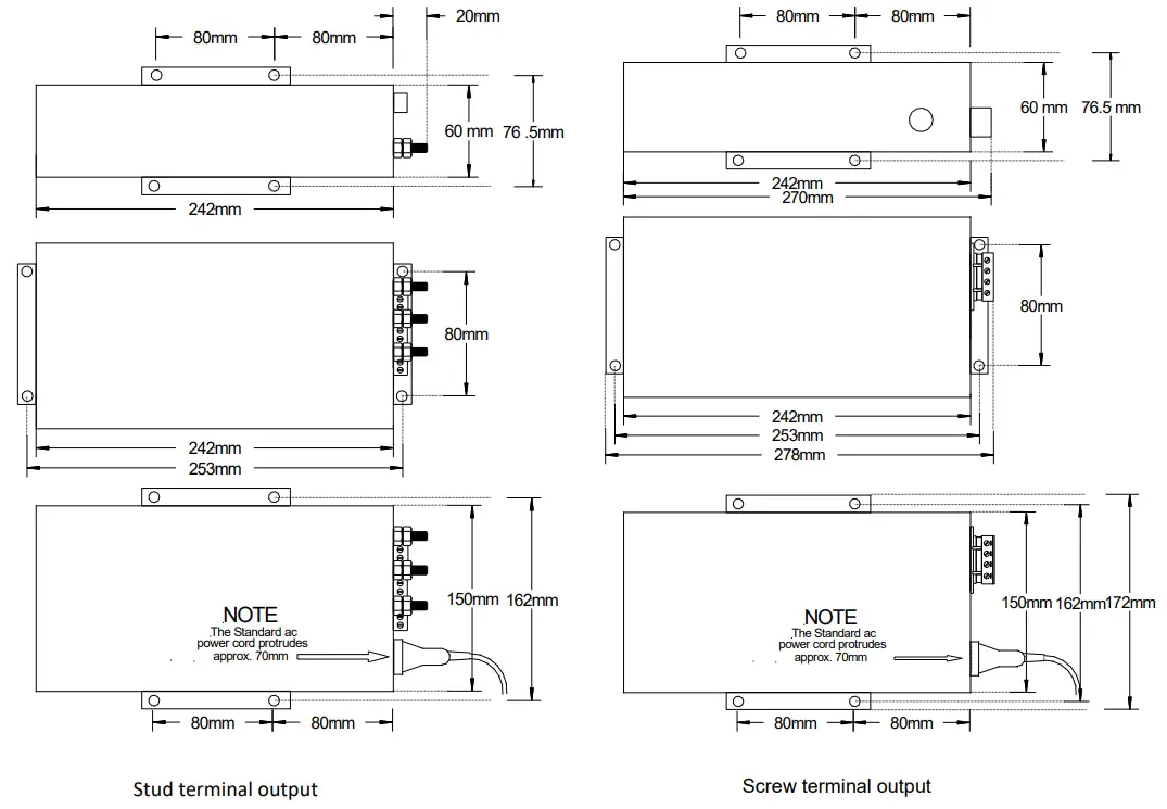
MOUNTING DETAILS
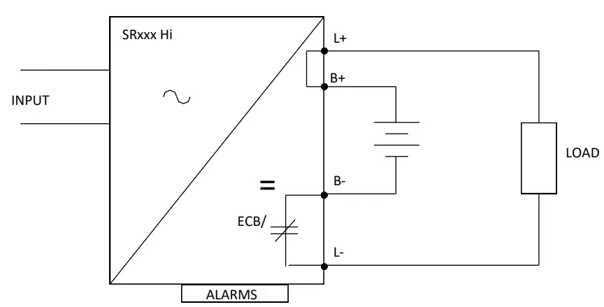
SR250HI CONNECTIONS – Typical Examples
- Standard No-Break™DC charger and battery bank
This is the basic connection which is most commonly used, and provides adequate protection for the majority of systems requiring DC back up in the event of a mains power failure.
| Alarms Available | |
| Input Fail | YES |
| Battery Missing | YES |
| Battery Low | YES |
| Battery Condition Test Fail | YES |
Note: On stud connected output models the L+/B+ is one stud labelled “+ COMMON”
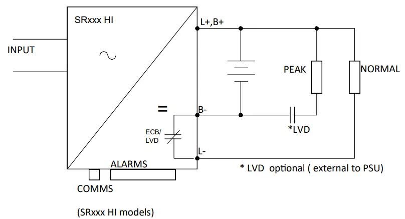
- Peak load connection using No-Break™DC charger
Peak loads which may exceed 1.5 x max. charger output can be connected to bypass the internal overcurrent trip circuit.
| Alarms Available | |
| Input Fail | YES |
| Battery Missing | YES |
| Battery Low | YES |
| Battery Condition Test Fail | YES |
- N+1 connection using two complete No-Break™DC systems with each one capable of supplying the loads- positive common
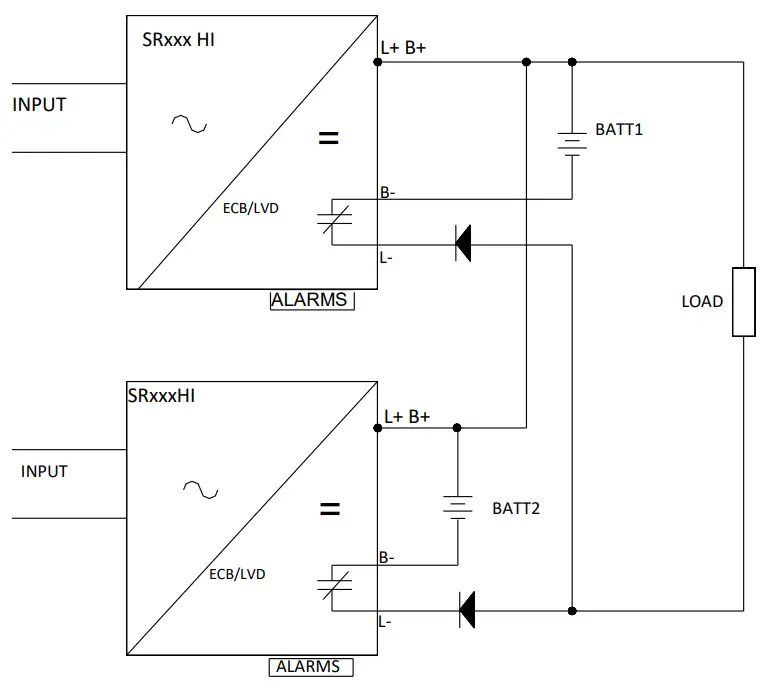
| Alarms available | |
| Power OK | YES |
| Battery missing | YES |
| Battery low | YES |
| Battery condition test fail *1 | YES |
*1 interlock circuit required for automated BCT
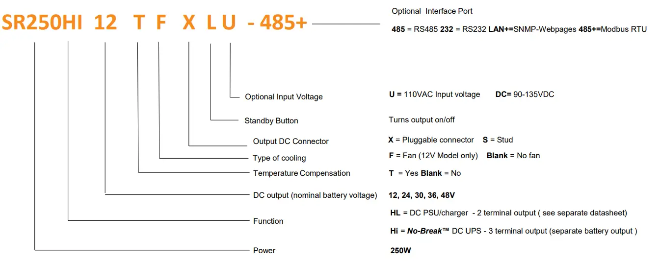
MODEL CODING AND OPTIONS
TECHNICAL SPECIFICATIONS
| Output power | 250W |
| Input Voltage | 180V – 264VAC & 88V-132VAC 45-65Hz |
| Output Voltages | 12V, 24V, 30V, 36V, 48 VDC |
| Voltage Atli. Range | 85%- 120% of Vnominal |
| Overcurrent protection | Constant current limit under overload and short circuit conditions |
| Isolation | Input – earth – 2.5KVdc Output- earth – SO0Vdc |
| Efficiency | > 85% |
| Operating temperature | -20 to 50 *C ambient at full load |
| Humidity | 0 – 95% relative humidity non – condensing |
| Cooling | Natural convection except for 12 V model (fan) |
| LVD | Low Voltage Disconnect |
| LED Indication | Green: Batt OK Green: Power OK Red: Standby |
| Alarms Relay | Form C contacts 30VDC,2A/110VDC,0.3A,125VAC, 0.5A AUX (Activated by BC7) POWER (main falls, PSI) fails) BATTERY (bait missing, bait low, BCT fail) |
| Temp. Compensation | Temperature sensor On 1.7m lead with adhesive pad: -4mV/ t/ cell ± 10% |
| Battery Charge Current Limit | Customizable on request. |
| Reverse Polarity | Battery reverse connection will open internal fuse (and produce alarm) |
| Mon BatteryMonitoring | Detects for presence of battery on start up, then every 60 minutes when charge current < 200mA |
| Battery Circuit Protection | Electronic circuit breaker (ECB) operates under the following conditions: |
| – Low Battery Volts: Battery Voltage drops to 1.67V/cell | |
| Overload: Max load must not exceed 110% of rated current. Peak loads must be connected to B. & B- terminals. (Not suitable for N♦1 connection) | |
| Short Circuit: <2ms, backed up by fuse | |
| Standby Mode | Turns off DC output of PSU & allows load to run off battery |
| Line Regulation | < 0.2% over AC Input range |
| Load Regulation | < 0.4% open circuit to 100% load |
| Noise | < 1% output voltage |
| Thermal Protection | Yes, self-resetting |
| Hold-up Time | 15 – 20 ms (nom – max. Vin) without battery |
| AC Input connector | IEC60320— C13 10A input sod<et (similar to PCs etc) |
| DCConnections | Plug-in style socket & mating screw terminal block: (max. wire 2.5mm’ / way) or M6 brass stud |
| Alarm connections | Plug in screw terminal block |
| Enclosure | Zinc plated & powder coated steel |
| Dimensions | 242W x 150Dx 61H (± 1mm) |
| Weight | 1.8 Kg |
STANDARDS
| EMC | To CISPR 22 / EN55022 class A |
| Safety | To IEC950 / EN60950 / AS/NZS3260 |
CUSTOMISED MODELS
| Model code | BASE MODEL | SPECIAL FEATURES |
| CSR171 | SR250HI24TFXL | BCT enabled 1hr/ 7days |
| CSR159 | SR250HI12TFSL | BCT enabled 20mins/ 28days, V pres = 12V |
| CSR200 | SR250HI12TFSL | No fan, rated output at 50degC = 210W |
TERMS OF WARRANTY
Helios Power Solutions warrants this product for 24 months from date of shipment against material and workmanship defects. Liability under this warranty is limited to the replacement or repair of the defective product as long as the product has not been amaged through misapplication, negligence, or unauthorized modification or repair.
w Zealand: [email protected] –
Australia: [email protected] –
Middle East & Asia: [email protected]
12121212


