
Power Walker VI RLP Series UPS
IMPORTANT SAFETY INSTRUCTIONS
This manual contains important instructions. Please read and follow all instructions carefully during installation and operation of the unit. Read this manual thoroughly before attempting to unpack, install, or operate the UPS.
- CAUTION! The UPS must be connected to a grounded AC power outlet with fuse or circuit breaker protection. DO NOT plug the UPS into an outlet that is not grounded. If you need to power-drain this equipment, turn off and unplug the unit.
- CAUTION! The battery can power hazardous components inside the unit, even when the AC input power is disconnected. CAUTION! The UPS should be placed near the connected equipment and easily accessible.
- CAUTION! To prevent the risk of fire or electric shock, install in a temperature and humidity controlled indoor area, free of conductive contaminants. (Please see specifications for acceptable temperature and humidity range).
- CAUTION! (No User Serviceable Parts): Risk of electric shock, do not remove cover. No user serviceable parts inside. Refer servicing to qualified service personnel.
- CAUTION! (Non-Isolated Battery Supply): Risk of electric shock, battery circuit is not isolated from AC power source; hazardous voltage may exist between battery terminals and ground. Test before touching.
- CAUTION! To reduce the risk of fire, connect the UPS to a branch circuit with 10 amperes (850 / 1K / 1.5K) / 16 amperes (2K / 3K) maximum over-current protection in accordance with CE requirement.
- CAUTION! The AC outlet where the UPS is connected should be close to the unit and easily accessible.
- CAUTION! Please use only VDE-tested, CE-marked mains cable, (e.g., the mains cable of your equipment), to connect the UPS to the AC outlet.
- CAUTION! Please use only VDE-tested, CE-marked power cables to connect any equipment to the UPS.
- CAUTION! When installing the equipment, ensure that the sum of the leakage current of the UPS and the connected equipment does not exceed 3.5mA.
- CAUTION! The 1000 / 2000 / 3000 / Battery module models are only qualified maintenance personnel may carry out installations. CAUTION! Do not unplug the unit from AC Power during operation, as this will invalidate the protective ground insulation. CAUTION! To avoid electric shock, turn off and unplug the unit before installing the input/output power cord with a ground wire. Connect the ground wire prior to connecting the line wires!
- CAUTION! Do not use an improper size power cord as it may cause damage to your equipment and cause fire hazards. CAUTION! Wiring must be done by qualified personnel.
- CAUTION! DO NOT USE FOR MEDICAL OR LIFE SUPPORT EQUIPMENT! Under no circumstances this unit should be used for medical applications involving life support equipment and/or patient care.
- CAUTION! DO NOT USE WITH OR NEAR AQUARIUMS! To reduce the risk of fire, do not use with or near aquariums. Condensation from the aquarium can come in contact with metal electrical contacts and cause the machine to short out. CAUTION! Do not dispose of batteries in fire as the battery may explode.
- CAUTION! Do not open or mutilate the battery, released electrolyte is harmful to the skin and eyes.
- CAUTION! A battery can present a risk of electric shock and high short circuit current. The following precaution should be observed when working on batteries
- Remove watches, rings, or other metal objects.
- Use tools with insulated handles.
- CAUTION! The unit has a dangerous amount of voltage. When the UPS indicators is on, the units may continue to supply power thus the unit’s outlets may have a dangerous amount of voltage even when it’s not plugged in to the wall outlet.
- CAUTION! Make sure everything is turned off and disconnected completely before conducting any maintenance, repairs, or shipment.
- CAUTION! Connect the Protection Earth (PE) safety conductor before any other cable is connected.
- WARNING! (Fuses): To reduce the risk of fire, replace only with the same type and rating of fuse.
- DO NOT INSTALL THE UPS WHERE IT WOULD BE EXPOSED TO DIRECT SUNLIGHT OR NEAR A STRONG HEAT SOURCE! DO
- NOT BLOCK OFF VENTILATION OPENINGS AROUND THE HOUSING!
- DO NOT CONNECT DOMESTIC APPLIANCES SUCH AS HAIR DRYERS TO UPS OUTPUT SOCKETS!
- SERVICING OF BATTERIES SHOULD BE PERFORMED OR SUPERVISED BY PERSONNEL KNOWLEDGE OF BATTERIES AND
- THE REQUIRED PRECAUTIONS. KEEP UNAUTHORIZED PERSONNEL AWAY FROM BATTERIES!
UNPACKING
(1) UPSx1; (2) User’s manual x1; (3) Input power cord x1; (4) Flat head screws: M4x8Lx8; (5) Rackmount trail (optional)x1; (6) Screw hole dust covers x1; (7) Rackmount ears (Stands)x2; (8) USB communication cable (optional)x1.
BASIC OPERATION
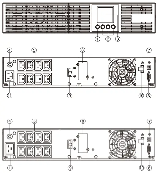
UPS FRONT/REAR PANEL DESCRIPTION
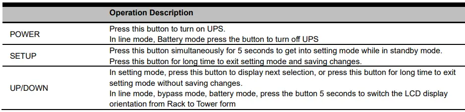
- Power On/Off Button
Master ON/OFF for the UPS. - Function Buttons
Scroll up, scroll down, select, and cancel LCD menu in setting mode. - Multifunction LCD Readout
Indicate status information, settings, and events. - Input Circuit Breaker
Provide input overload and fault protection. - Independent Outlets
Provide battery backup and surge protection. They ensure power is provided to connected equipment over a period of time during a power failure. Most important, the 8 outlets can be set up and work independently. - Serial Port
Serial port provides communication between the UPS and the computer. The UPS can control the computer’s shutdown during a power outage through the connection while the computer can monitor the UPS and alter its various programmable parameters. - USB port
This is a connectivity port which allows communication and control between the UPS and the connected computer. It is recommended to install the Power master software on the PC/Server connected with the USB cord. - SNMP/HTTP Network slot
Slot to install the optional “SNMP card 2” for remote network control and monitoring. - Extended Runtime Battery Module Connector Connect to additional external battery modules.
- EPO (Emergency Power Off) Connector
Enable Power-Off in emergency from a remote location. - AC Input Inlet
Connect the AC Power cord to a properly wired and grounded outlet.
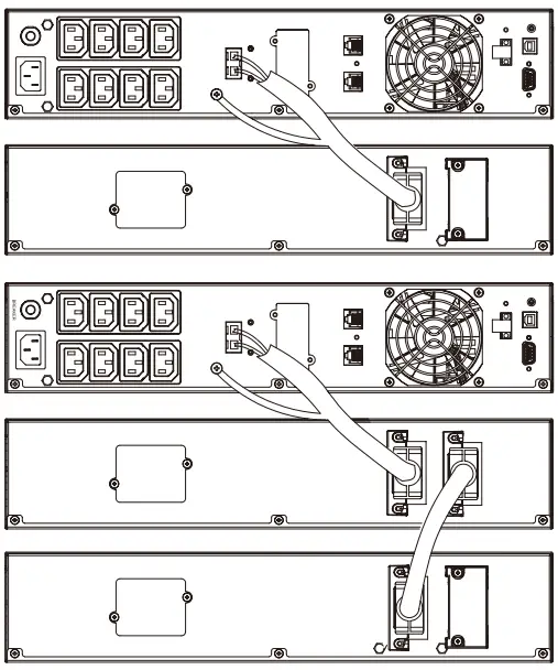
- UPS – External Battery Module Connection (1) : Single Battery Pack Installation
- Step1: Use the battery cable of the Battery module to connect
the Battery module to the UPS module. - Step 2: Use screws to fix ground connection.
- Step1: Use the battery cable of the Battery module to connect
- UPS – External Battery Module Connection (2) : Multiple Battery Packs Installation
- Step 1: Connect the 1st Battery module to the UPS module using battery cable.
- Step 2: Use the battery cable to connect the 2nd Battery module to the 1st Battery module.
- Step 3: Use screws to fix ground connection.

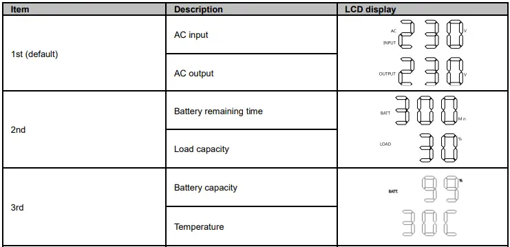
DEFINITIONS FOR OTHER ICONS
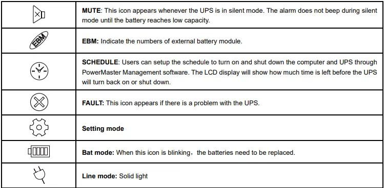
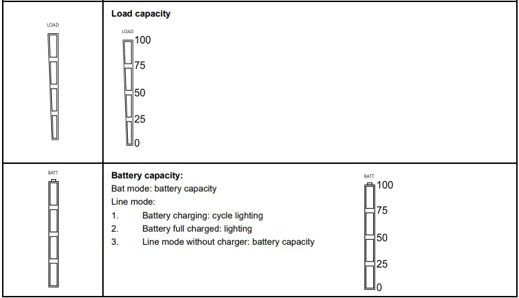
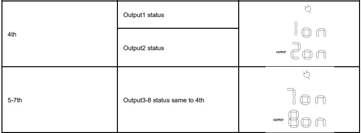
LCD DISPLAY
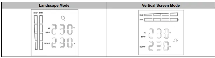
- Press the display key “UP/DOWN” to indicate the different item


- Press the “UP/DOWN” button simultaneously for 3 seconds to activate or exit the vertical screen mode.


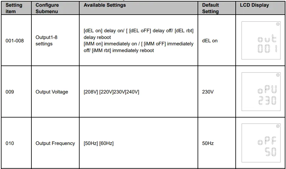
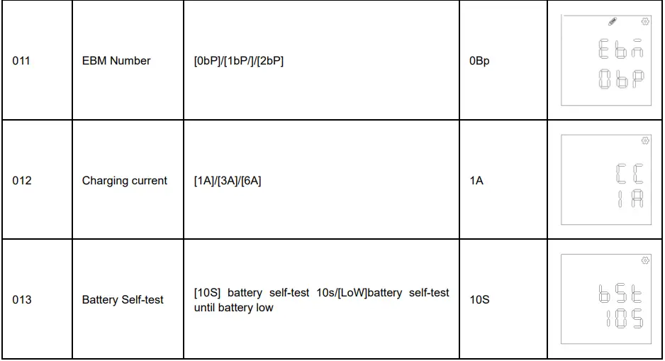
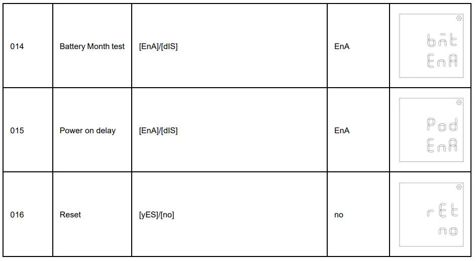
LCD SETTINGS CONFIGURATION
There are 9 UPS settings that can be configured by the user.
- Press the “SETUP” button for 5 seconds to activate or exit the setting mode.
The first configuration parameter will be displayed on the LCD screen.
Note: The manual settings programming mode can ONLY be invoked while UPS is in Standby mode. To make UPS on Standby mode, connect utility power to UPS and do not turn on UPS. - Press the “UP/DOWN” button to scroll different page or the different parameters.
- Press the “ENTER” buttons to select the parameter you want.


Event ID Descriptions
| Event ID | Description of Case | Remedy |
| E05 | INV soft Start Fail | Restart the UPS, if the fault is still, please contact Technical Support. |
| E07 | INV Volt High | |
| E08 | INV Volt Low | |
| E09 | INV Short | Your attached equipment may have problems, please remove them, and check again. |
| E11 | Bat Volt High |
Shutdown the ups and check the battery connect or replace them, then restart the ups. |
| E12 | Bat Volt Low | |
| A59 | Bat Disconnect | |
| A62 | Bat Bad | |
| A56 | Bat Volt Low | |
| A64 | Overload Warning | Shut off the non-essential equipment then UPS may be normal. |
| E14 | Overload | |
| E18 | Fan Fail | Shutdown the ups and check the fan or replace, then the UPS can work normally. |
| A69 | Fan Lock | |
| E19 | Over Temperature | Environment or UPS temperature may too high, move UPS to a cool environment or shut off the non-essential equipment. |
| A68 | Over Temperature | |
| A66 | EPO Active | Check the EPO terminal, it may fall off, install it again will be ok. |
TECHNICAL SPECIFICATIONS
| Model | 1000R | 2000R | 3000R |
| Configuration | |||
| Capacity (VA) | 1000VA | 2000VA | 3000VA |
| Capacity (Watts) | 900W | 1800W | 2700W |
| Form Factor | Rack/Tower | ||
| Input | |||
| Input Voltage Range | 165 VAC ~290VAC | ||
| Input Frequency Range | 45~65Hz | ||
| Input Power Factor | 0.98 | ||
| Cold Start | Yes | ||
| Output | |||
| Output Waveform | Pure Sine Wave | ||
| Output Voltage | 230Vac ±10% | ||
| Output Frequency | 50 / 60Hz (Auto Sensing or Configurable) ±1%Hz | ||
| Transfer Time (Typically) | 2~6ms typical, 10ms max | ||
| Rated Power Factor | 0.9 | ||
| Protection | |||
| Surge Protection | IEC 61000-4-5 Level 4 | ||
|
Overload Protection | Line Mode: >110% alarm continuous <100% go back
AVR & Battery Mode >110% Fault after 1MIN <100% go back >120% Fault immediately | ||
| Short Circuit Protection | UPS Output Cut off Immediately or Input Fuse / Circuit Breaker Protection | ||
| Battery | |||
| Specifications | (12V/9AH) *2 | (12V/9AH) *4 | (12V/9AH) *6 |
| Recharge Time (Typically) | 4 Hours (inside batteries) | ||
| Sealed, Maintenance Free | Yes | ||
| Status Indicators | |||
| LCD Screen | Graphic LCD | ||
| Audible Alarms | Battery Mode, Battery Low, Overload, UPS Fault, Replace Battery, Bypass Mode Charger Failure /Over Charged, Fan failure, EPO active, over temperature etc. | ||
| Environment | |||
| Operating Temperature | 32℉ to 104℉ (0℃ to 40℃) | ||
| Operating Relative Humidity | 10to 90% non-Condensing | ||
| Management | |||
| On-Device Features | Self-Test, Auto-Charge, Auto-Restart, Auto-Overload Recovery | ||
| Connectivity Ports | (1) Serial Port (RS232). (1) USB Port | ||
| SNMP/HTTP Capable | (1) Expansion Port | ||
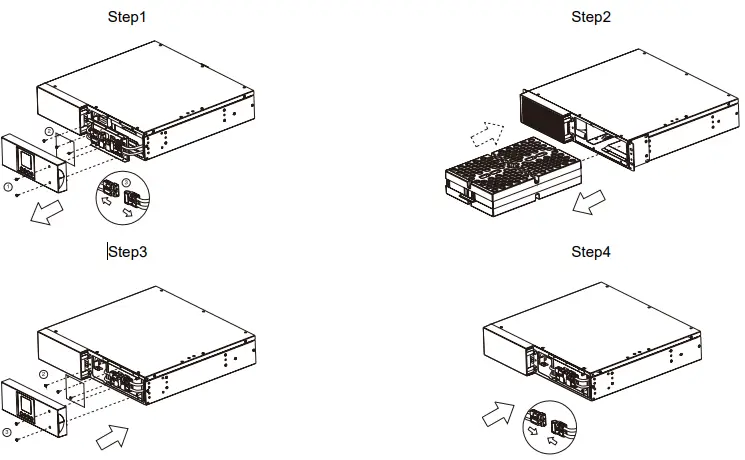
BATTERY INSTALL ATION AND REPLACEMENT
- Step 1: Remove the front panel. Remove the retaining screws from the battery bracket and then remove the cover itself. Disconnect
the connectors. - Step 2: Pull the battery tray out slowly. Put the new battery tray back into the compartment after that.
- Step 3: Fasten the battery bracket and then insert the connectors. Place the connectors in the bracket.
- Step 4: Tighten the screws of the battery bracket and front panel.

TROUBLE SHOOTING
| Problem | Possible Cause | Solution |
| Warning | ||
| O/P Overload | Your equipment requires more power than the UPS can provide. If the UPS is in Line Mode, then it will transfer to Bypass Mode; if the UPS is in Battery Mode, it will shut down. | Shut off non-essential equipment. If this solves the overload problem, the UPS will transfer to normal operation. |
| Battery Mode | UPS is operating on battery power. | Save your data and perform a controlled- shutdown. |
| Battery Low | UPS is operating on battery power and will be shutting down soon due to extremely low battery voltage. | UPS will restart automatically when acceptable utility power returns. |
| BAT Disconnected/ Battery Replace | Missing battery power. | Check battery connector when use battery packages. |
| UPS has failed in Battery Test. | Contact technical support to replace the battery. | |
| Charger Failure | Charger has failed. | 1. Shut down UPS and turn off AC input. 2. Contact the dealer for repair. |
| EPO OFF | Missing the EPO connection. | Check the EPO connection. |
| Fault | ||
| Over Temperature | High ambient temperature. | 1. Shut down UPS. Restart UPS to Check the fan for operation and if the ventilation hole has been covered 2. Contact the dealer for repair. |
| Output Short | Output short circuit. | 1. Shut down UPS 2. Your attached equipment may have problems, please remove them and check again. |
| High O/P V | Output voltage is too high. | 1. Shut down UPS 2. Contact the dealer for repair. |
| Low O/P V | Output voltage is too low. | |
| Bus Fault | Internal DC bus voltage is too high or too low. | |
| Other | ||
| Startup fail | High temperature, or fan fail, or battery low, or EPO off. | 1. Restart UPS and press the “▼” button to view the warning event. Then refer to the solution for the warning. 2. Contact the dealer for repair. |
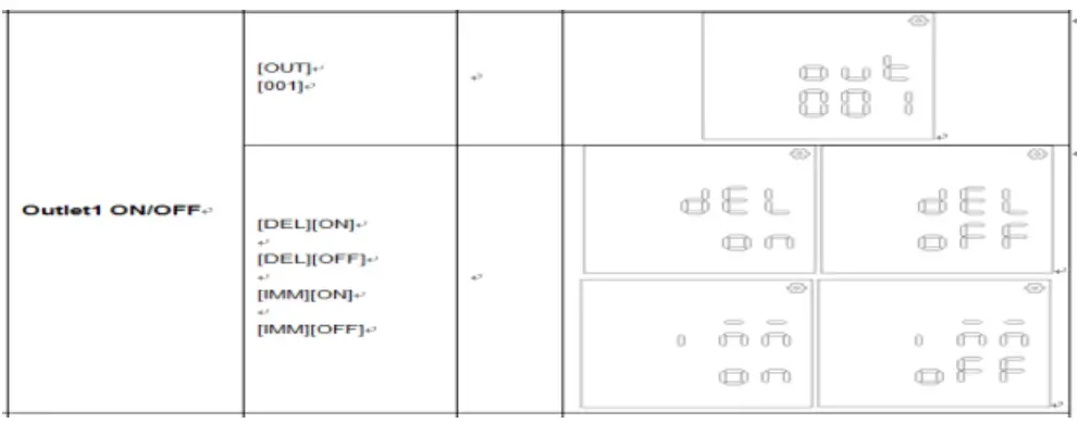
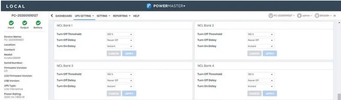
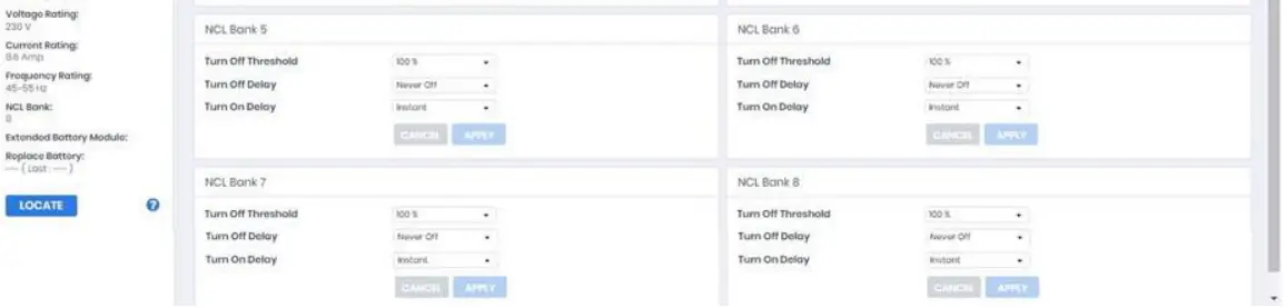
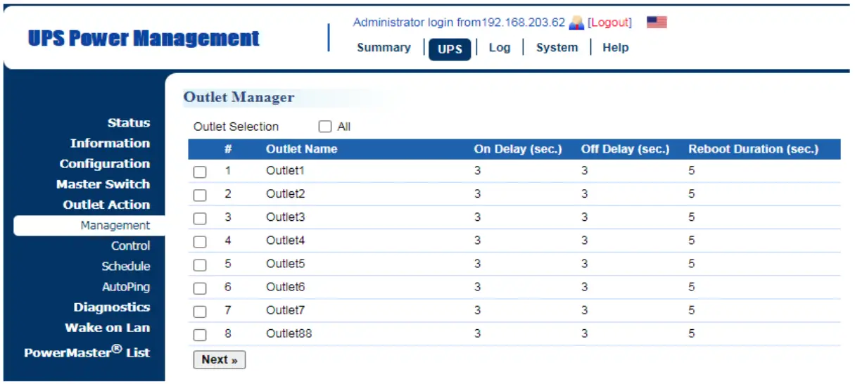
INDIVIDUAL OUTLET CONTROL
- Method 1: Through LCD setting: Setting item 001-008
- Method 2: Through PowerMaster+ Local: [UPS SETTING->CONFIGURATION]


- Method 3: Trough SNMP Card 2 Webpage: [UPS->Outlet Action->Outlet Management]

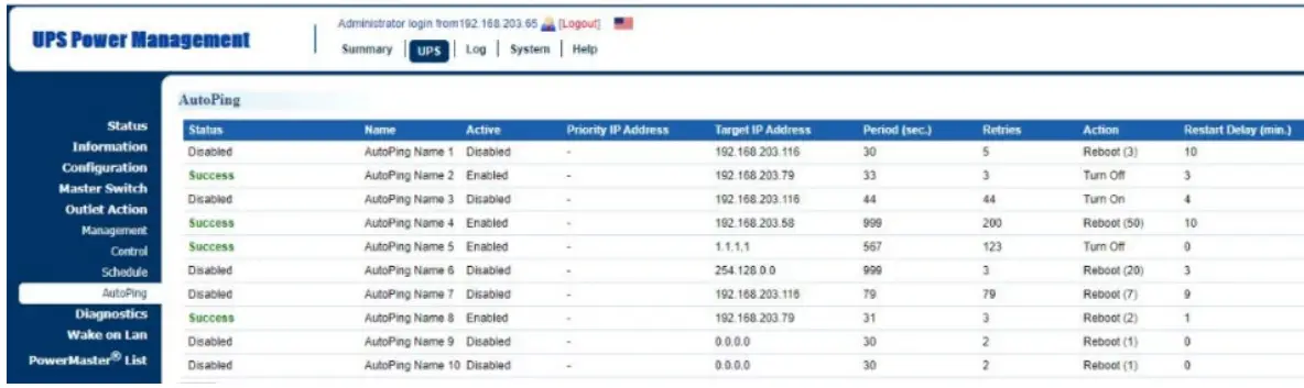
AUTO-PING
The Auto-Ping feature allows the SNMP Card 2 to detect if a target device becomes unresponsive to IP pings and automatically reboot the device. If the device gets back to normal operation after reboot, network connection could be restored at the same time. First add an IP address of the target device and correlate the IP address to specific outlet, which powers the device. The SNMP Card 2 begins to verify its connection to the internet by periodically sending IP pings to the device. If the SNMP Card 2 continuously receives no response from the device, the setting action will be triggered on the outlet. To utilize the function, AutoPing configuration is based on different applications
Auto Ping setting: [UPS->Outlet Action->Outlet AutoPing]
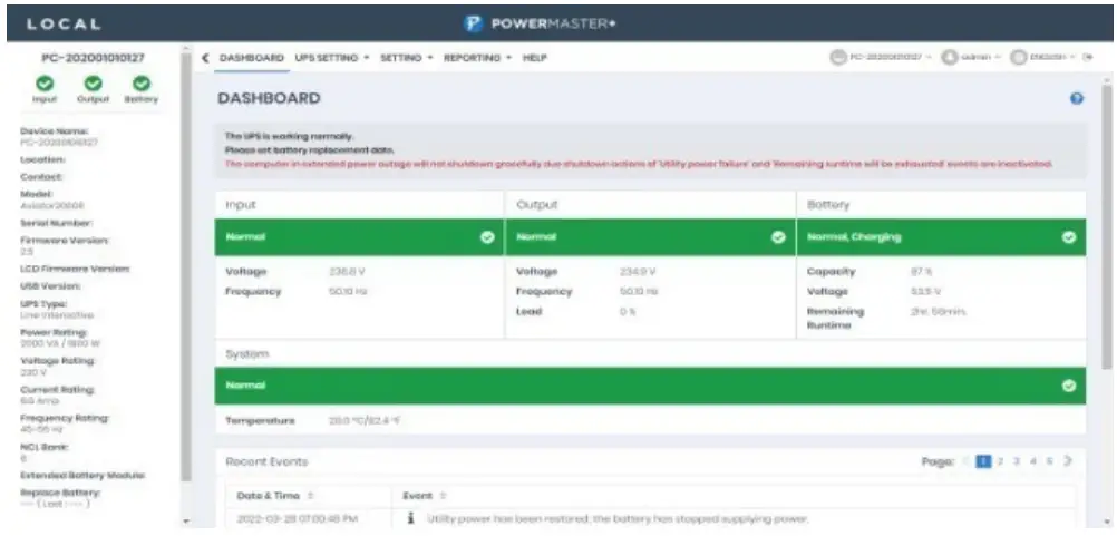
SOFTWARE DOWNLOAD
Power Master+ management software provides a user-friendly interface for your power systems. The graphic user-interface is intuitive and displays essential power information at a glance. Please follow procedure below to install the software.
Installation procedure:
- Download PowerMaster from the website: https://powerwalker.com/software/#powermaster
- Double-click the file and follow the installation steps.
When your computer restarts, the PowerMaster software will appear as a blue icon located in the system tray.


