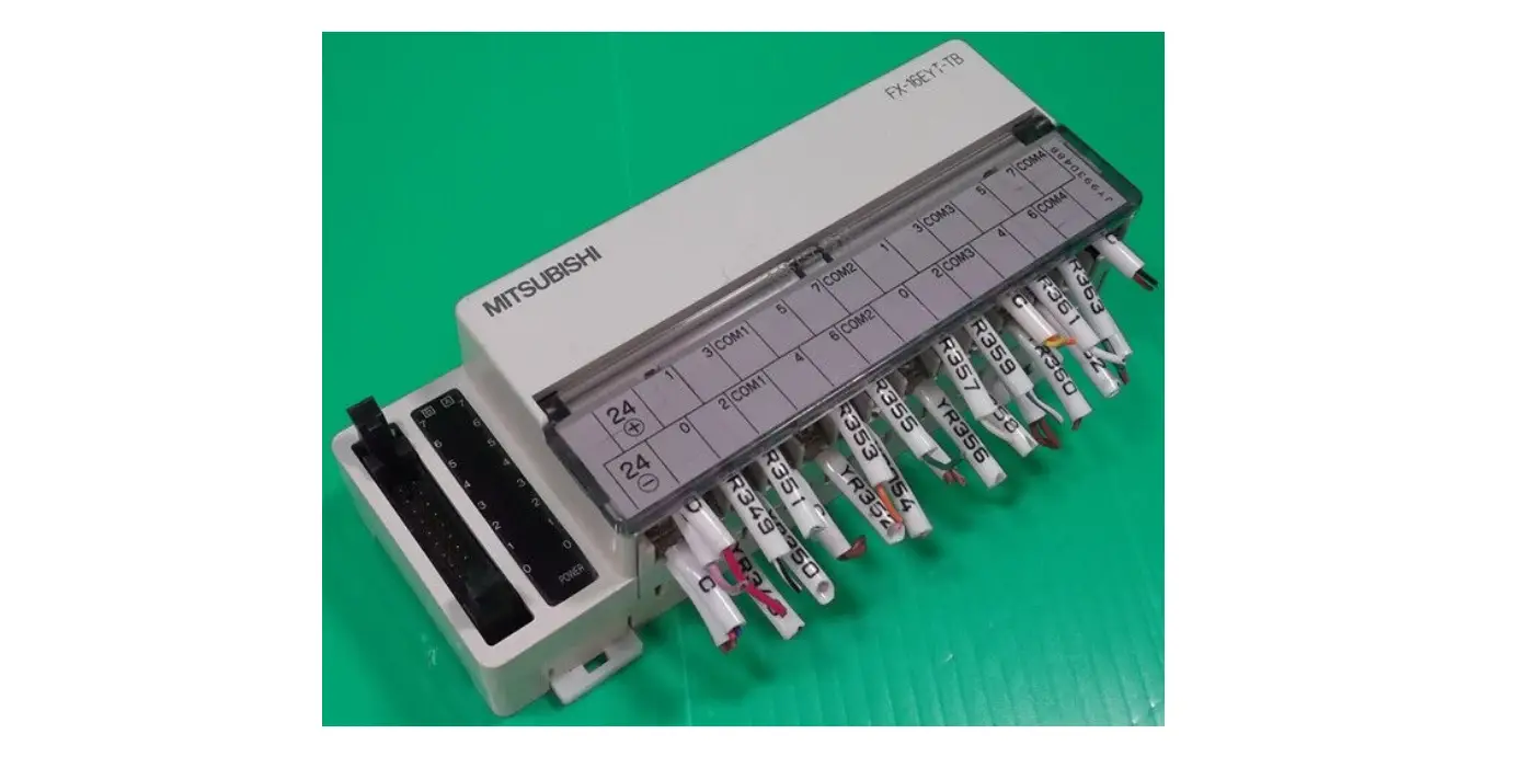
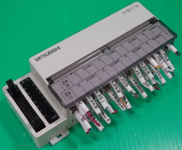
MITSUBISHI ELECTRIC FX-16EYT-TB Connector
This manual contains text, diagrams and explanations which will guide the reader in the correct installation and operation of the FX TERMINAL BLOCKS. It should be read and understood before attempting to install or use the unit. Further information can be found in the FX series PLC hardware manuals. If in doubt at any stage during the installation of the FX TERMINAL BLOCKS always consult a professional electrical engineer who is qualified and trained to the local and national standards.
All terminal blocks described in this manual conform to the UL/cUL Standard.
Note’s on the symbology used in this manual
At various times through out this manual certain symbols will be used to highlight points of information which are intended to ensure the users personal safety and protect the integrity of the equipment. Whenever any of the following symbols are encountered, its associated note must be read and understood. Each of the symbols used will now be listed with a brief description of its meaning.
Hardware warnings
- Indicates that the identified danger WILL cause physical and property damage.
- Indicates that the identified danger could POSSIBLY cause physical and property damage.
Guidelines for the safety of the user and protection of the FX TERMINAL BLOCKS
- This manual has been written to be used by trained and competent personnel. This is defined by the European directives for machinery, low voltage and EMC.
- If in doubt at any stage during the installation of the FX TERMINAL BLOCKS always consult a professional electrical engineer who is qualified and trained to the local and national standards. If in doubt about the operation or use of the FX TERMINAL BLOCKS please consult the nearest Mitsubishi Electric distributor.
- Under no circumstances will Mitsubishi Electric be liable or responsible for any consequential damage that may arise as a result of the installation or use of this equipment.
- All examples and diagrams shown in this manual are intended only as an aid to understanding the text, not to guarantee operation. Mitsubishi Electric will accept no responsibility for actual use of the product based on these illustrative examples.
- Owing to the very great variety in possible application of this equipment, you must satisfy yourself as to its suitability for your specific application.
INTRODUCTION
Terminal blocks convert I/O terminals of connector type PLC into terminal blocks. Some terminal blocks directly extend inputs and outputs of PLC. Other terminal blocks are equipped with diversified built-in devices, and function only as inputs or only as outputs.
| MODEL | INPUT | OUTPUT | APPLICABLE PLC | CURRENT CONSUMPTION |
| FX-16E-TB/UL | 16 pt (Direct input/output) | FX2C-MT-ESS/UL FX2NC-MT-DSS FX2NC-EX-DS FX2NC-EYT-DSS FX2C-MT-E/UL | ||
| FX-32E-TB/UL | 32 pt or 16/16 pt (Direct input/output) | |||
| FX-16EYR-ES-TB/UL | 16 pt (Relay) | FX2C-ooMT-ESS/UL FX2NC-ooMT-DSS FX2NC-ooEYT-DSS | 80mA (5mA/1pt) | |
| FX-16EYS-ES-TB/UL | 16 pt (Triac) | 112mA (7mA/1pt) | ||
| FX-16EYT-ESS-TB/UL | 16 pt (Transistor source) | |||
| FX-16EYT-ES-TB/UL | 16 pt (Transistor sink) | |||
| FX-16EX-A1-TB/UL | 16 pt (100V AC) | FX2C-ooMT-E/UL | 48mA (3mA/1pt) | |
| FX-16E-TB | 16 pt (Direct input/output) | FX2NC-MT-D/UL FX2NC-EX-D/UL FX2NC-EYT-D/UL |
| |
| FX-32E-TB | 32 pt or 16/16 pt (Direct input/output) | |||
| FX-16EYR-TB | 16 pt (Relay) | FX2NC-MT-D/UL FX2NC-EYT-D/UL | 80mA (5mA/1pt) | |
| FX-16EYT-TB | 16 pt (Transistor sink) | 112mA (7mA/1pt) | ||
| FX-16EX-A1-TB | 16 pt (100V AC) | FX2NC-ooMT-D/UL FX2NC-ooEX-D/UL | 48mA (3mA/1pt) | |
EXTERNAL DIMENSION
FX-16E-TB/UL, FX-16E-TB
FX-16EY(: R/T/S)-TB/UL
FX-16EY(: R/T)-TB
FX-16EX-A1-TB/UL, FX-16EX-A1-TB
FX-32E-TB/UL
FX-32E-TB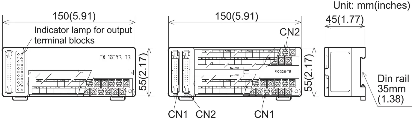 Accessories
- Input / output extension block labels
- Terminal layout cards
CONFIGURATION AND OPTIONS
| STANDARD PRE TERMINATED CABLES | ||
| LENGTHS | FLAT CABLES | ROUND CABLES |
| 1.5 m (4.9 ft) | FX-16E-150CAB | FX-16E-150CAB-R |
| 3.0 m (9.8 ft) | FX-16E-300CAB | FX-16E-300CAB-R |
| 5.0 m (16.4 ft) | FX-16E-500CAB | FX-16E-500CAB-R |
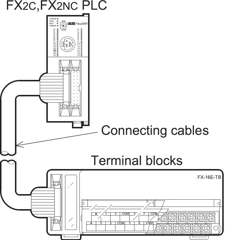
CONNECTOR CABLE PIN CONFIGURATION
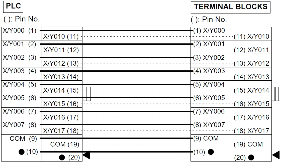
The connections required between the FX2C, FX2NC main unit and a terminal block are shown in the dia-gram below with an example for inputs X000 to X017 and outputs Y000 to Y017. The I/O connector should be the 20-pin type and should conform to MIL C 83503 of Military Standard.
TERMINAL WIRING
- Never perform external wiring to unused terminals . Such wiring may damage the unit.
Note
- Do not lay I/O cables next to power cables or allow them to share the same trunking duct.
- Where I/O signals are used over an extended distance consideration must be made for voltage drop and noise interference.
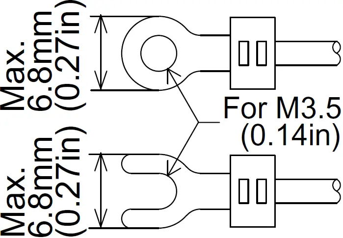
- Use crimp-style terminals of the dimensions shown in the figure below.
- Tighten terminals at a torque of 0.5 to 0.8 N·m (4.4 to 7.1 lbf·in). Do not tighten the terminal block mounting screws with a torque outside the above-mentioned range. Failure to do so may cause equipment failures or malfunctions.
DIRECT INPUT BLOCKS AND DIRECT OUTPUT BLOCKS WIRING
Internal circuit
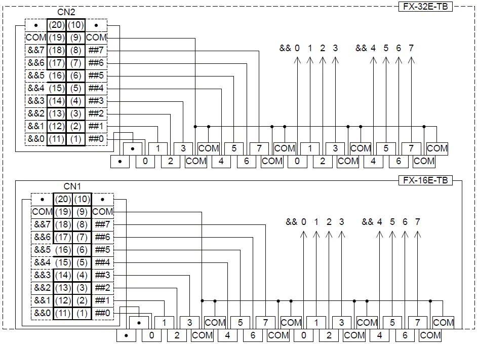
- (9) and (19) of both CN1 and CN2 are short-circuited internally.
Inputs
| PLC | TYPICAL WIRING | |
| TYPE | ||
FX2C-ooMT-ESS/UL | Source (-ve S/S) | 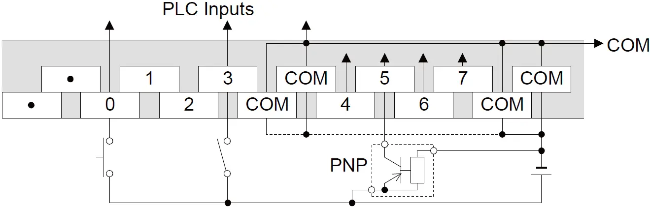 |
| Sink (+ve S/S) | 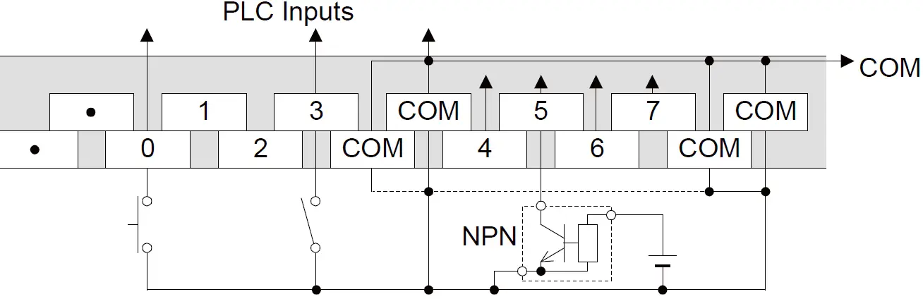 | |
FX2C-ooMT-E/UL FX2NC-ooMT-D/UL FX2NC-ooEX-D/UL | Sink | |
FX2NC-ooMT-DSS FX2NC-ooEX-DS | Source |  |
Sink | 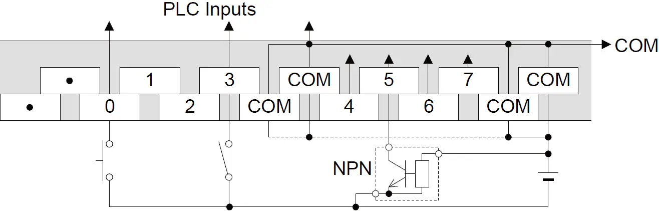 |
Outputs
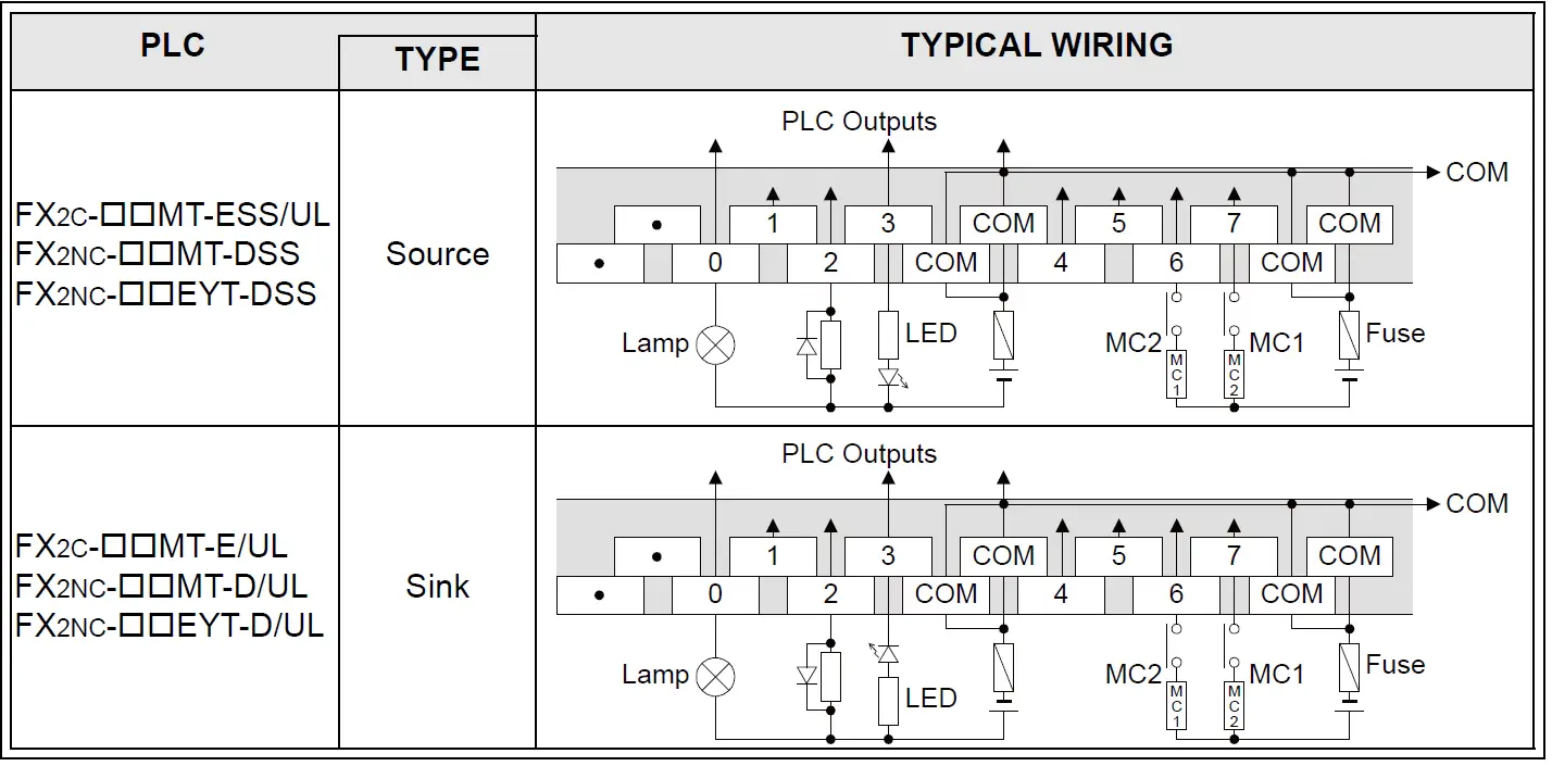
For the I/O specifications and detailed information, refer to the FX2C Hardware Manual or the FX2NC Hard-ware Manual.
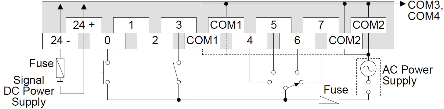
AC INPUT BLOCK WIRING
Specifications
| Input | Voltages | 85 – 132V AC 50/60Hz |
| Impedance | 21kW / 50Hz 18kW / 60Hz | |
| Current | 6.2mA 110V AC/60Hz 4.7mA 100V AC/50Hz | |
| Circuit isolation | Photocoupler | |
| Operation indication | LED of base unit | |
| Switch Rating | OFF ð ON | 80V 3.8mA |
| ON ð OFF | 30V 1.7mA | |
| Response time | 30ms or less | |
| Signal input supply | 24V DC 3mA/1pt | |
Typical wiring
OUTPUT BLOCKS WIRING
Outputs specification
| RELAY | TRIAC | TRANSISTOR | ||
| Switched voltages | Less than 250V AC 30V DC | Between 85 – 242V AC | 5 – 30V DC | |
| Circuit isolation | By relay coil | Photocoupler | Photocoupler of base unit | |
| Operation indication | LED is lit when coil is active. | LED is lit when output is active. | LED is lit when output is active. | |
Maximum load | resistive | 2A/pt 8A/4pts(com) | 0.3A/pt 0.8A/4pts(com) | 0.5A/pt 0.8A/4pts(com) |
| inductive | 80VA | 15VA, 100V AC 36VA, 240V AC | 12W 24V DC | |
| indicator | 100W | 30W | 1.5W 24V DC | |
| Leakage current | 1mA, 100V AC 2mA, 200V AC | 0.1mA 30V DC | ||
| Minimum load | 2mA 5V DC | 0.4VA, 100V AC 1.6VA, 200V AC | ||
| Response time | OFFðON | Approx. 10ms | Less than 2ms | Approx. 0.2ms |
| ONðOFF | Less than 12ms | Approx. 1.5ms | ||
| Indicator input supply | 24V DC 5mA/1pt | 24V DC 7mA/1pt | 24V DC 7mA/1pt | |
Relay output blocks FX-16EYR-ES-TB/UL, FX-16EYR-TB wiring
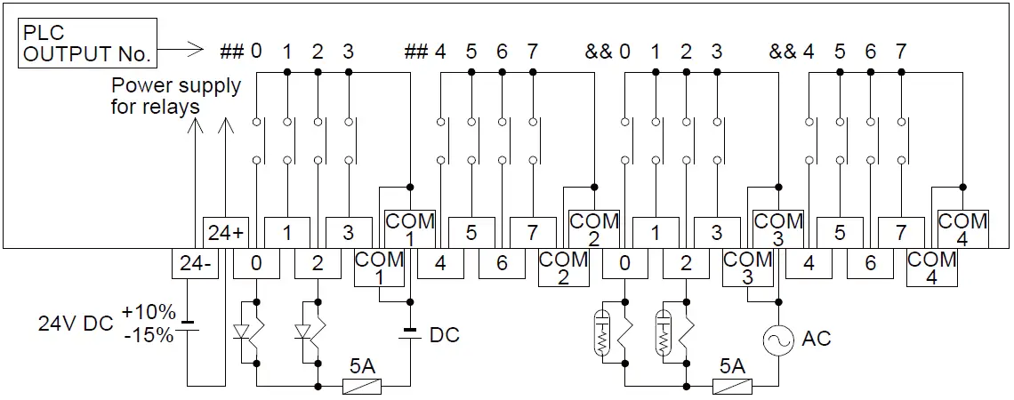 Terminal blocks are not equipped with built-in fuses. In order to prevent breakdown of circuits caused by load short-circuit, provide a fuse of 5 to 10 A for every four points.
[ DC LOAD ]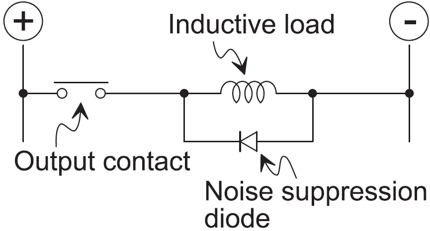 Connect a noise suppression diode to a DC inductive load in parallel. If the diode is not connected, the life time of the contact becomes considerably shorter. Select a noise suppression diode whose reverse withstand voltage is 5 to 10 times or more the load voltage and whose current in the for-ward direction is not less than the load current.
[ AC LOAD ]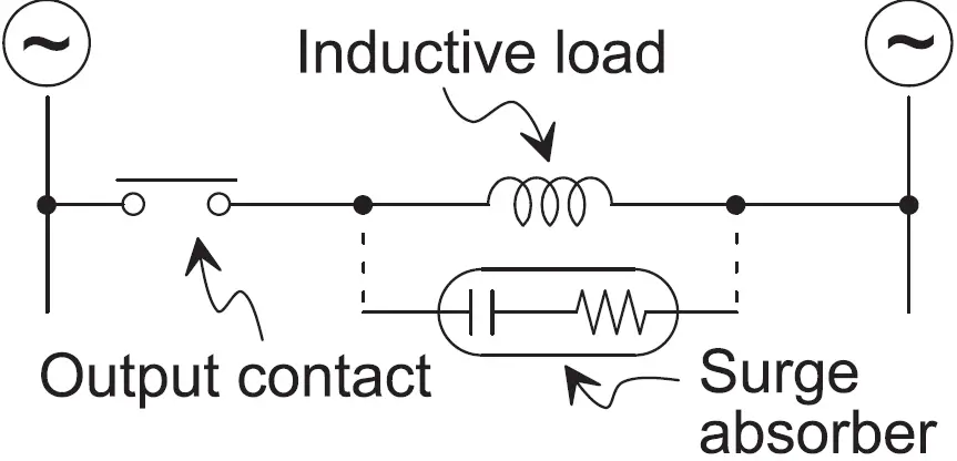 When a surge absorber is connected to an AC inductive load in parallel, noise generation is reduced.
0.1 F capacitor + 100 to 120 resistor
The standard life time of contactors and solenoid valves against AC inductive load is 500,000 times of actuation against 35 VA. The table below shows the guideline of the life time of relays based on the result of the life time test per-formed in our company. Have in mind that the life time of a relay contact becomes considerably shorter even in the condition below if the rush current is shut down.
| LOAD CAPACITY (Test condition: ON for 1 second and OFF for 1 second) | LIFE TIME OF CONTACT | EXAMPLE OF APPLICABLE LOAD (Magnetic switch manufactured by our company) | |
| 35VA | 0.35A / 100V AC | 3,000,000 times | S-K10 ~ S-K150 S-N10 ~ S-N35 |
| 0.17A / 200V AC | |||
| 80VA | 0.8A / 100V AC | 1,000,000 times | S-K180 ~ S-K400 |
| 0.4A / 200V AC | |||
| 120VA | 1.2 / 100V AC | 200,000 times | S-K600, S-K800 |
| 0.6A / 200V AC | |||
Triac output block FX-16EYS-ES-TB/UL wiring
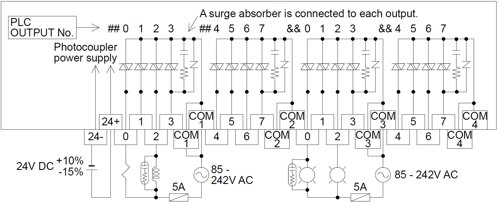 Terminal blocks are not equipped with built-in fuses. In order to prevent breakdown of circuits caused by load short-circuit, provide a fuse of 5 to 10 A for every four points.
[ MINUTE CURRENT LOAD ]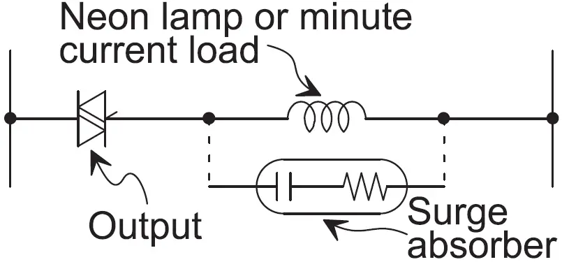 To a neon lamp or a minute current load of 0.4VA/100V AC, 1.6VA/200V AC or less, connect a surge absorber in parallel.
[ OUTPUT CURRENT ]
The current of 0.3 A can flow in each output point. However, in order to restrict temperature rise, flow 0.8 A to every four output points (= 0.2 A per point on an average). When turning on and off frequently a load with large rush current, set the square average current to 0.2 A or less.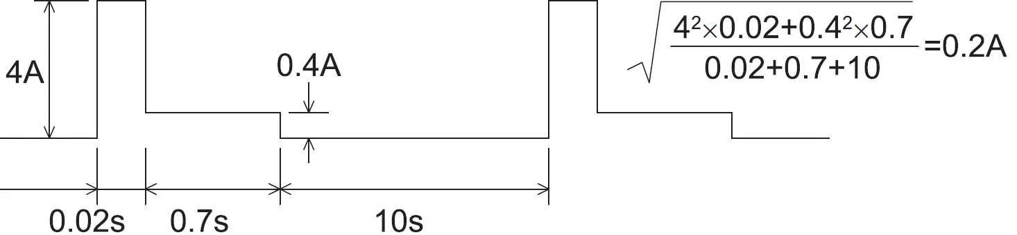 Transistor output blocks wiring
FX-16EYT-ESS-TB/UL (source)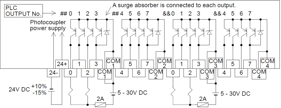 FX-16EYT-ES-TB/UL, FX-16EYT-TB (sink)
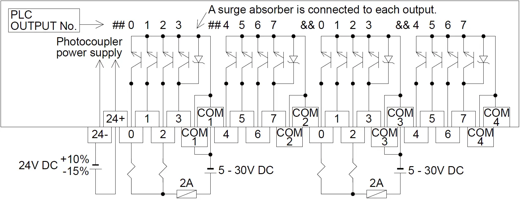 Terminal blocks are not equipped with built-in fuses. In order to prevent breakdown of circuits caused by load short-circuit, provide a fuse of 2 A for every four points.
[ ON VOLTAGE ]
The ON voltage of an output transistor is approximately 1.5 V. When driving a semiconductor device, etc., pay attention to the input voltage characteristics of the used device.
Manual number : JY992D50401
Manual revision: L
Date : May 2022


