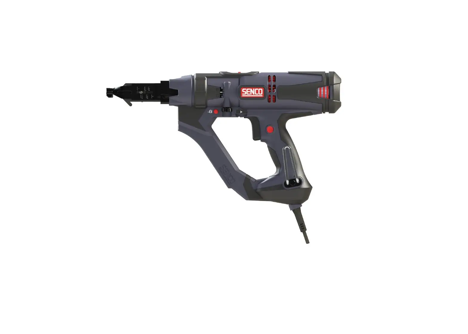
DURASPIN DS242-AC Auto-Feed Screw Driver Instruction Manual
Symbols
| The following signal words and meanings are intended to explain the levels of risk associated with this product. | ||
| SYMBOL | SIGNAL | MEANING |
 | DANGER: | Indicates a hazardous situation, which, if not avoided, will result in death or serious injury. |
| | WARNING: | Indicates a hazardous situation, which, if not avoided, could result in death or serious injury. |
| | CAUTION: | Indicates a hazardous situation, which, if not avoided, may result in minor or moderate injury. |
| NOTICE: | (Without Safety Alert Symbol) indicates information considered im- portant, but not related to a potential injury (e.g. messages relating to property damage). | |
| Some of the following symbols may be used on this product. Please study them and learn their meaning. Proper interpretation of these symbols will allow you to operate the product in a better, safer manner. | ||
| SYMBOL | NAME | DESIGNATION/EXPLANATION |
| | Safety Alert | Indicates a potential personal injury hazard. |
 | Read Operator’s Manual | To reduce the risk of injury, user must read and understand opera- tor’s manual before using this product. |
 | Eye Protection | Always wear eye protection with side shields marked to comply with ANSI Z87.1. |
 | Wet Conditions Alert | Do not expose to rain or use in damp locations. |
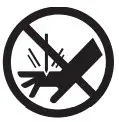 | No Hands | Failure to keep your hands away from blade will result in serious personal injury. |
V | Volts | Voltage |
min | Minutes | Time |
| Direct Current | Type or characteristic of current | |
| Alternating Current | Type or characteristic of current |
no | No Load Speed | Rotational speed, at no load |
…/min | Per Minute | Revolutions, strokes, surface speed, orbits, etc. per minute |
General Power Tool Safety Warnings
WARNING Read all safety warnings, instructions, illustrations and specifications
provided with this power tool. Failure to follow all instructions listed below may result in electric shock, fire and/or serious injury.
Save all warnings and instructions for future reference.
The term “power tool” in the warnings refers to your mains-operated (corded) power tool or battery-operated (cordless) power tool.
Work Area Safety
- Keep work area clean and well lit. Cluttered or dark areas invite accidents.
- Do not operate power tools in explosive atmospheres, such as in the presence of flammable liquids, gases or dust. Power tools create sparks which may ignite the dust or fumes.
- Keep children and bystanders away while operating a power tool. Distractions can cause you to lose control.
Electrical Safety - Power tool plugs must match the outlet. Never modify the plug in any way. Do not use any adapter plugs with earthed (grounded) power tools. Unmodified plugs and matching outlets will reduce risk of electric shock.
- Avoid body contact with earthed or grounded surfaces, such as pipes, radiators, ranges and refrigerators. There is an increased risk of electric shock if your body is earthed or grounded.
- Do not expose power tools to rain or wet conditions. Water entering a power tool will increase the risk of electric shock.
- Do not abuse the cord. Never use the cord for carrying, pulling or unplugging the power tool. Keep cord away from heat, oil, sharp edges or moving parts. Damaged or entangled cords increase the risk of electric shock.
- When operating a power tool outdoors, use an extension cord suitable for outdoor use. Use of a cord
suitable for outdoor use reduces the risk of electric shock. - If operating a power tool in a damp location is unavoidable, use a residual current device (RCD) protected supply. Use of an RCD reduces the risk of electric shock.
Personal Safety - Stay alert, watch what you are doing and use common sense when operating a power tool. Do not use a power tool while you are tired or under the influence of drugs, alcohol or medication. A moment of inattention while operating power tools may result in serious personal injury.
- Use personal protective equipment. Always wear eye protection. Protective equipment such as dust mask, non-skid safety shoes, hard hat or hearing protection used for appropriate conditions will reduce personal injuries.
- Prevent unintentional starting. Ensure the switch is in the off-position before connecting to power source and/or battery pack, picking up or carrying the tool. Carrying power tools with your finger on the
switch or energizing power tools that have the switch on invites accidents. - Remove any adjusting key or wrench before turning the power tool on. A wrench or a key left attached to a rotating part of the power tool may result in personal injury.
- Do not overreach. Keep proper footing and balance at all times. This enables better control of the power tool in unexpected situations.
- 15. Dress properly. Do not wear loose clothing or jewelry. Keep your hair, clothing and gloves away from moving parts. Loose clothes, jewelry or long hair can be caught in moving parts.
- If devices are provided for the connection of dust extraction and collection facilities, ensure these are connected and properly used. Use of dust collection can reduce dust-related hazards.
- Do not let familiarity gained from frequent use of tools allow you to become complacent and ignore tool safety principles. A careless action can cause severe injury within a fraction of a second.
Power Tool Use and Care - Do not force the power tool. Use the correct power tool for your application. The correct power tool will do the job better and safer at the rate for which it was designed.
- Do not use the power tool if the switch does not turn it on and off. Any power tool that cannot be controlled with the switch is dangerous and must be repaired.
- Disconnect the plug from the power source and/or remove the battery pack, if detachable, from the power tool before making any adjustments, changing accessories, or storing power tools. Such preventive
safety measures reduce the risk of starting the power tool accidentally. - Store idle power tools out of the reach of children and do not allow persons unfamiliar with the power tool or these instructions to operate the power tool. Power tools are dangerous in the hands of untrained users.
- Maintain power tools and accessories. Check for misalignment or binding of moving parts, breakage of parts and any other condition that may affect the power tool’s operation. If damaged, have the power tool repaired before use. Many accidents are caused by poorly maintained power tools.
- Keep cutting tools sharp and clean. Properly maintained cutting tools with sharp cutting edges are less likely to bind and are easier to control.
- Use the power tool, accessories and tool bits etc. in accordance with these instructions, taking into account the working conditions and the work to be performed. Use of the power tool for operations
different from those intended could result in a hazardous situation. - Keep handles and grasping surfaces dry, clean and free from oil and grease. Slippery handles and grasping surfaces do not allow for safe handling and control of the tool in unexpected situations.
Service - Have your power tool serviced by a qualified repair person using only identical replacement parts. This will ensure that the safety of the power tool is maintained.
Screwdriver Safety Warnings
- Hold the power tool by insulated gripping surfaces, when performing an operation where the fastener may contact hidden wiring. Fasteners contacting a “live” wire may make exposed metal parts of the power tool “live” and could give the operator an electric shock.
- Do not use the power tool in locations where the ambient temperature may reach 4°C (39.2°F) or exceed 40˚C (105˚F).
Functional Description
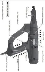
Tool Operation
Read sections titled “Safety Warnings” before operating tool.
Read and understand all in-structions. Failure to follow all instructions listed below may result in electric shock, fire and/or serious personal injury.
WARNING Do not use this product if it is not completely assembled or if any parts appear to be missing or damaged. Use of a product that is not properly and completely assembled or with damaged or missing parts could result in serious personal injury.
WARNING Do not attempt to modify this product or create accessories or attachments not recommended for use with this product. Any such alteration or modification is misuse and could result in hazardous conditions possibly leading to serious personal injury.
I any parts are damaged or missing, please call 1-800-543-4596 for assistance.
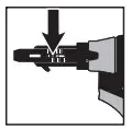
Adjusting for Fastener Length
- Unplug tool from electrical supply before adjusting nose-piece for fastener length.
- Depress the screw selector pin until it is flush with nosepiece and slide the nosepiece to the desired setting by aligning hatch marks with the silver adjustment pin.
- Release pin and make sure it is fully engaged in selected nosepiece slot for proper operation.

| DS242-AC | DS245-AC | DS342-AC |
| 1″ | 1″ | 1″ |
| 1 1/4″ | 1 1/4″ | 1 1/4″ |
| 1 1/2″ | 1 1/2″ | 1 1/2″ |
| 1 3/4″ | 1 3/4″ | 1 3/4″ |
| 1 5/8″ | 1 5/8″ | 1 5/8″ |
| 2″ | 2″ | 2″ |
| 2 1/4″ | ||
| 2 1/2″ | ||
| 2 3/4″ | ||
| 3″ |
| Bit Type | DS242/DS245 | DS342 |
| Phillips | EA0297 | EA0400 |
| Square | EA0298 | EA0401 |
| Rex | EA0299 | EA0402 |
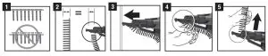
Loading the Tool
- Check to be sure the heads of the screws are resting on top of the plastic collation material. This will ensure proper strip advancement and prevent jamming.

- Check for proper fastener length setting (see “Adjusting for Fastener Length” above).
- Feed the strip into the strip guide track up toward the nose of the tool.
- Feed the strip into the slide body until the first screw is aligned with the bit. The tool will feed all subsequent screws automatically as the tool is pulled back off the work surface, returning to its relaxed state.
- To remove the strip, pull it through from the top of the side body.
Driving Screws
- Whenever possible, hold the tool at a right angle to the work surface.
- Pull the trigger to start the motor.
- Press the nosepiece with constant force against the work surface. Do not remove the tool from the work surface until the clutch disengages and the bit stops rotating, signalling a fully driven screw.
- Continue to allow the motor to run. The next screw will be automatically fed into place when the tool is pulled off the work surface.
Trigger Lock
To lock the trigger for continuous operation, depress the trigger and push in the locking button then release the trigger. The tool will continue to run. To turn off, squeeze and release the trigger.
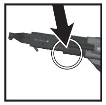
Depth of Drive Adjustment
This tool is equipped with a locking depth control adjustment:
- Release the thumbwheel by depressing the red lock button.

- Adjust the countersink by turning the depth adjustment thumbwheel.
- Refer to the markings on the tool for proper direction.
- Release the lock button after adjustment.
Test drive screws while adjusting until the desired countersink is reached.
This tool has a depth-sensing clutch. When the screw is countersunk to the preset depth, it automatically disengages and makes a click or ratcheting sound. This is normal and signals completion of the drive.
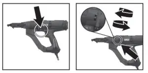
Bit Replacement
Due to wear or damage, the bit will need to be replaced periodically or when changing between drive types.
The bit can be removed/replaced:
- Without removing feed system
- Remove fasteners from the tool.
ii. Slide bit release button to rear. - Tilt tool forward and pulse trigger.
- Bit will fall out.
- Hold tool upright.
- Insert the new bit into the slide body.
- Slide bit release button to rear.
- Pulse tool and release button when bit drops into place.
- Remove fasteners from the tool.
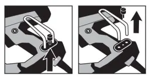
Nosepiece Replacement
- Unplug the tool before changing the nosepiece.
- Remove retention screw with flat-tip screwdriver.

- Set the nosepiece on the longest setting possible.
- Depress the screw selector pin until it is completely depressed. It will be necessary to use a screw or thin object to depress to this depth.
- While holding the pin in this position, slide the nosepiece forward and off the slide body
- Install the new nosepiece.
- Replace the nosepiece retention screw ensuring it is seated snug against the slide body.
Belt Hook Adjustment
To adjust the belt hook offset from the tool:
- Remove the belt hook thumb screw until the locking plate can be removed.
- Slide the belt hook out to the desired position, replace the locking plate, then re-install the thumb screw.
To relocate the belt hook to opposite side of the tool:
- Remove the thumb screw, locking plate, threaded plate and belt hook.

- Insert the threaded plate on the opposite side of tool and re-install the hook at the desired position using locking plate and thumb screw.
Maintenance
Read section titled “Safety Warnings” before maintaining tool.
- With battery removed or cord disconnected, make daily inspection to ensure free movement of nosepiece and trigger.
Do not use tool if nosepiece or trigger sticks or binds. - Lubrication of the feed system is not necessary. DO NOT OIL.
- Wipe tool clean daily and inspect for wear, especially the bit and nosepiece. Replace as necessary.
WARNING Repairs other than those described here should be performed only by trained, qualified personnel. Contact SENCO for information at 1-800-543-4596.
Accessories
SENCO offers a full line of DuraSpin screws and accessories for your SENCO tools, including:
- Bits
- Storage Bag
- Assorted Nosepieces
- Safety Glasses
For more information or a fully illustrated catalogue of Senco accessories, contact your sales representative or call Senco at 1-800-543-4596.
Technical Specifications
Table 4 – DS242-AC Tech Specs | |
| VOLTAGE | 120V |
| CURRENT | 6 AMPS |
| RPM | 0-2500 REV/MIN |
| WEIGHT | 5.65 LBS. |
| HEIGHT | 9.65″ |
| LENGTH | 16.35″ |
| WIDTH | 3.23″ |
| FASTENER CAPACITY | 50 SCREWS (1 STRIP) |
| FASTENER LENGTH | 1-2″ |
| FASTER RANGE | #6-#12 |
| Table 5 – DS245-AC Tech Specs | |
| VOLTAGE | 120V |
| CURRENT | 6 AMPS |
| RPM | 0-5000 REV/MIN |
| WEIGHT | 5.54 LBS. |
| HEIGHT | 9.65″ |
| LENGTH | 16.34″ |
| WIDTH | 3.23″ |
| FASTENER CAPACITY | 50 SCREWS (1 STRIP) |
| FASTENER LENGTH | 1-2″ |
| FASTER RANGE | #6-#10 |
| Table 6 – DS342-AC Tech Specs | |
| VOLTAGE | 120V |
| CURRENT | 6 AMPS |
| RPM | 0-2500 REV/MIN |
| WEIGHT | 5.68 LBS. |
| HEIGHT | 9.65″ |
| LENGTH | 17.17″ |
| WIDTH | 3.23″ |
| FASTENER CAPACITY | 50 SCREWS (1 STRIP) |
| FASTENER LENGTH | 1-3″ |
| FASTER RANGE | #6-#12 |
Troubleshooting
| Problem/Symptom | Probable Cause | Corrective Action |
| Tool will not start or run slowly | No electrical power | Ensure tool is plugged in, check power supply (fuse) |
| Trigger switch is defective | Replace or return to Senco autho- rized service centre for repair | |
| Motor is defective | ||
| Tool will not fully drive fastener | Bit is worn or incorrect bit installed | Replace bit |
| Power capabilities of the tool have been exceeded | Discontinue use for that applica- tion | |
| Tool is in reverse | Switch tool to forward | |
| Depth of drive not set properly | See p. #8 | |
| Tool does not advance fastener | Screw length/nosepiece position is improperly set | See p. #9 |
| Return spring is weak or broken | Replace or return to authorized service centre for repair | |
| Defective collation material | Use Senco branded fasteners for optimum performance | |
| Defective slide body | Replace or return to authorized service centre for repair | |
| Screw strip is jammed in guide track | Ensure strip slides freely in guide track | |
| Screws “kick out” or misdrive during use | Screw length/nosepiece position is improperly set | See p. #9 |
| Incorrect bit installed | Ensure correct bit type and length are installed | |
| Defective or damaged feed system | Return to Senco or Authorized service centre for repair | |
| Bit will not install | Bit not properly inserted into drive shaft | See p. #8 |
| Clutch teeth not aligned | Pulse trigger while holding back release button | |
| Not a Senco bit | Use only the appropriate Senco bit | |
| Bit will not release | Not a Senco bit | Use only the appropriate Senco bit |
| Clutch teeth not aligned | Pulse trigger while holding back release button | |
| Bit slips off screw or screw is driven at an angle | Tool slid forward during drive | Hold tool firmly while driving |
| Bit is worn or broken | Replace bit | |
| Nosepiece is worn or damaged | Replace or return to Senco autho- rized service centre for repair |
| Fastener Jams | Screw length/nosepiece position is improperly set | See p. #7 |
| Defective collation material | Use Senco branded fasteners for optimum performance | |
| Nosepiece damaged or bent | Replace or return to authorized service centre for repair | |
| Screw partially driven into collation material then feed system released | Remove jammed screw with fingers or pliers and resume use | |
| Feed system “sticks” or returns slowly | Debris build-up on mechanism | Clean mechanism |
| Return spring is weak or broken | Replace or return to authorized service centre for repair | |
| Bit sticking in collation material | Use Senco branded fasteners for optimum performance | |
| Always attempt to store screws in cool dry place before use. Overheated collation can get soft and cause a delay in feed system return | ||
| Tool overheats | Drive application requires too much torque | Discontinue use for that applica- tion |
| Pushing force becomes excessive | Improper screw for application | Consider alternative fastener |
| CAM screw is loose or damaged | Tighten or replace CAM screw | |
| Debris build-up on mechanism | Clean mechanism |


