ATOMRC Penguin Twin Motor FPV RC Airplane Fixed Wing User Manual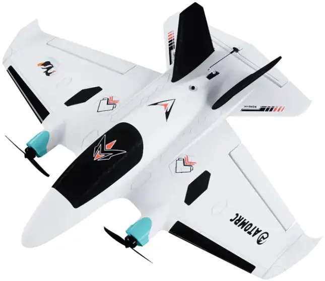
Introduction
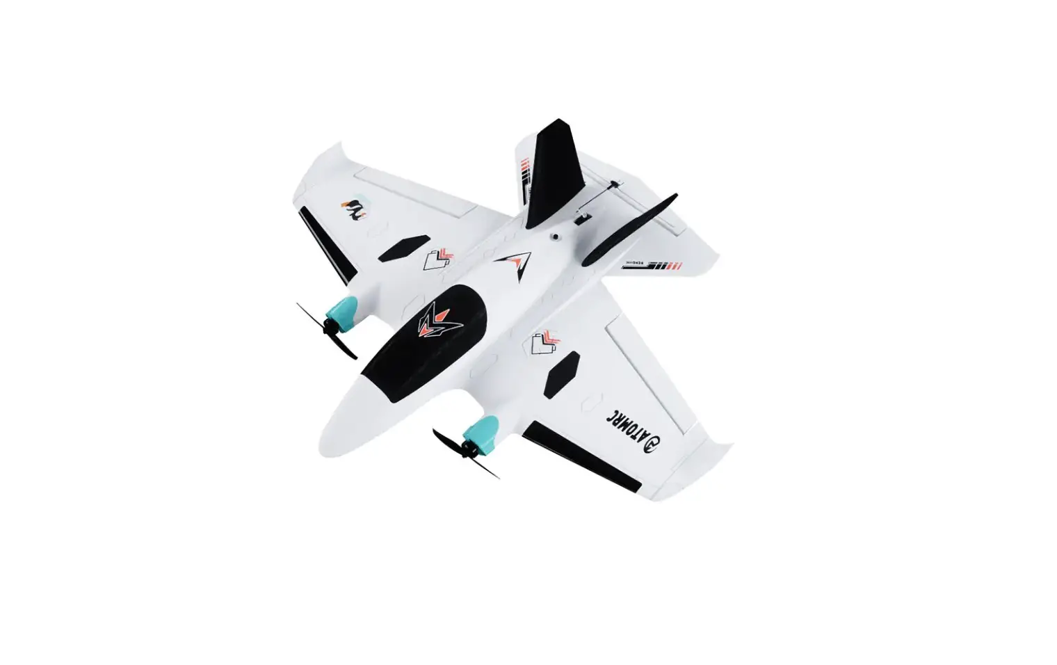
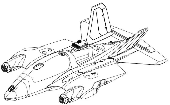
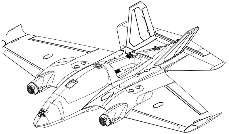
The Penguin is an FPV aircraft with 750mm wingspan, the wingsuit flight layout suitable for mid range flying in low altitudes chasing. the penguin has many advantages such as easy take-off and landing, in the full speed range. It retains the maneuverability of the traditional flying wing layout and improves the controllability of the height.
Allows you to fly with ease in FPV.
The new buckle design is fastened firmly, the left and right wings can be quickly disassembled, and the integrated built-in always-on navigation light increases the visibility of the aircraft. Penguin’s newly designed nose is compatible with most image transmission installations. After assembling the flight control equipment, the aircraft is easy to adjust the cg balance. Provide you with a stable flight experience. Whether you are a beginner or an experienced pilot, Penguin will give you most reliable flight experience
Specifications
| Penguin Specifications | |
| Wingspan | 750mm |
| Length | 640mm |
| WingArea | 15.06d㎡ |
| Servo | 9g Servo*3PCS |
| Material | EPP |
| Recommend Motor | 2004/2206 |
| Recommend ESC | BLS 30A 2~4S |
| Recommend Propeller桨: | 6024-2 |
| Recommend Weight | 1200g |
| Recommned Battery | 2000~3000mAh 4S Lipo (200g~300g) |
Version Description
| ATOMRC Penguin Fixed Wing | ||||
| Version | KIT | PNP+S | RTH | |
| Description | Pre-glued Fixed WING | PNP+Pre all electronics are installed | PNP+Pre-turned FC+GPS, all electronics are installed | |
| Basic Pack | √ | √ | √ | |
| √ | √ | √ | ||
| √ | √ | √ | ||
| √ | √ | √ | ||
| Motor | 2004 2400KV | 2PCS | 2PCS | |
| ESC | ATOMRC Exceed BLS 4s30A ESC | 2PCS | 2PCS | |
| Servo | S09M 9g | 3PCS | 3PCS | |
| Prop | Gemfan 6024-2 | 2PCS | 2PCS | |
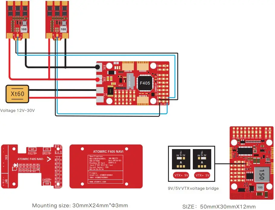
| FC | ATOMRC F405 NAVI | √ | ||
| GPS | BE220 | √ | ||
| The specs will be slightly adjusted according to different,actual specs are subject to the latest manual and real objects. | ||||
| ATOMRC | ||||
| KIT | PNP+S | RTH | ||
| √ | √ | √ | ||
| √ | √ | |||
| √ | √ | |||
| √ | √ | |||
| 2004 2400KV | 2PCS | 2PCS | ||
| ATOMRC Exceed BLS 4s30A ESC | 2PCS | 2PCS | ||
| S09M 9g | 3PCS | 3PCS | ||
| Gemfan 6024-2 | 2PCS | 2PCS | ||
| ATOMRC F405 NAVI | √ | |||
| GPS | BE220 | √ | ||
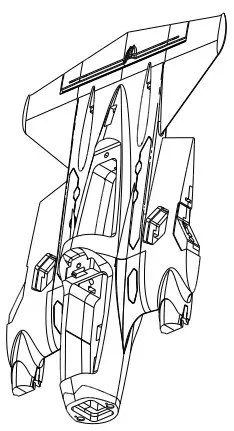
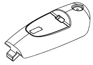
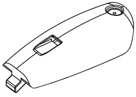
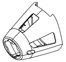
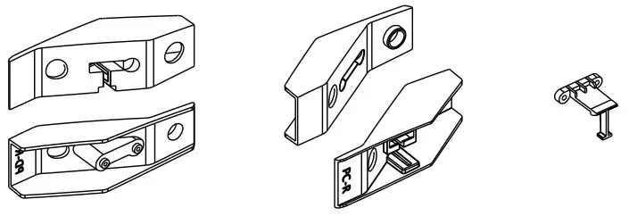
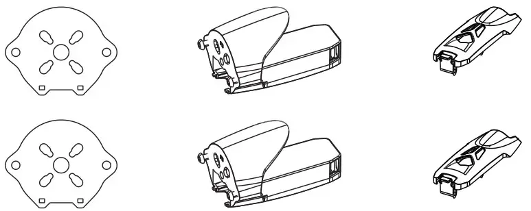
KIT Contents
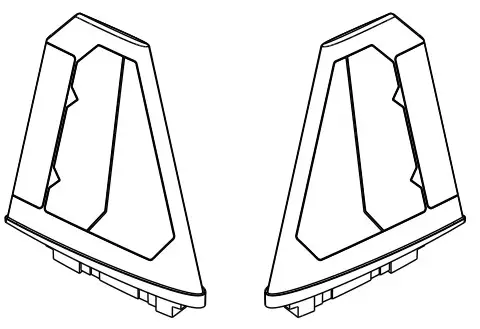
- FB-U/FB-D: Fuselage

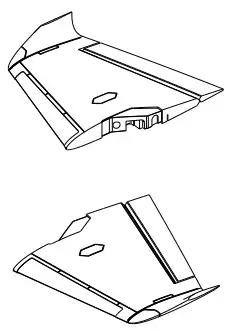
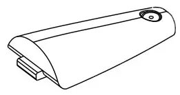
- FE-L/FE-R:Wing

- FF-L/FF-R:V Tail

- FA-U/FA-D::Nose

- FG-L/FG-R/FH:Wing hatch cover

- FD:Rear Hatch cover

- FC-A:Front Hatch cove

- FC:Front Hatch cove

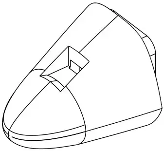
- PA:FPV Nose FPV

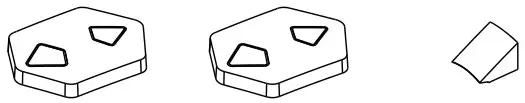
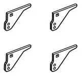
- PE-L/PE-R/PF-L/PF-R: Quick release Kit

- Sf1200 PA/PB/PC Motor Mount

- PF-L/PF-R/PG-L/PG-R:V Tail Flight Light Cover

- P1:Servo cove

- P2:Camera Mount

- P3:Control horn


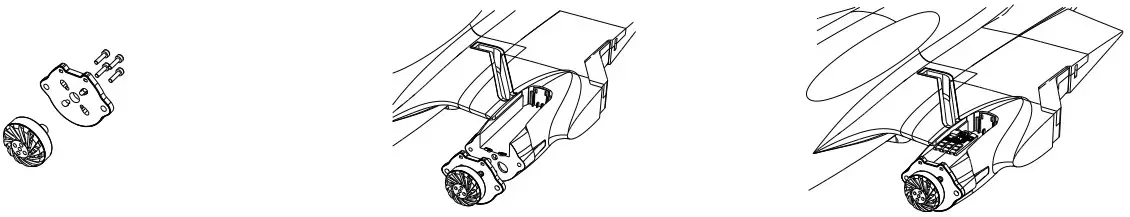
KIT Installation
- Install the motor,esc.power cable length suggest to 300mm

- Install the servo and push rods.

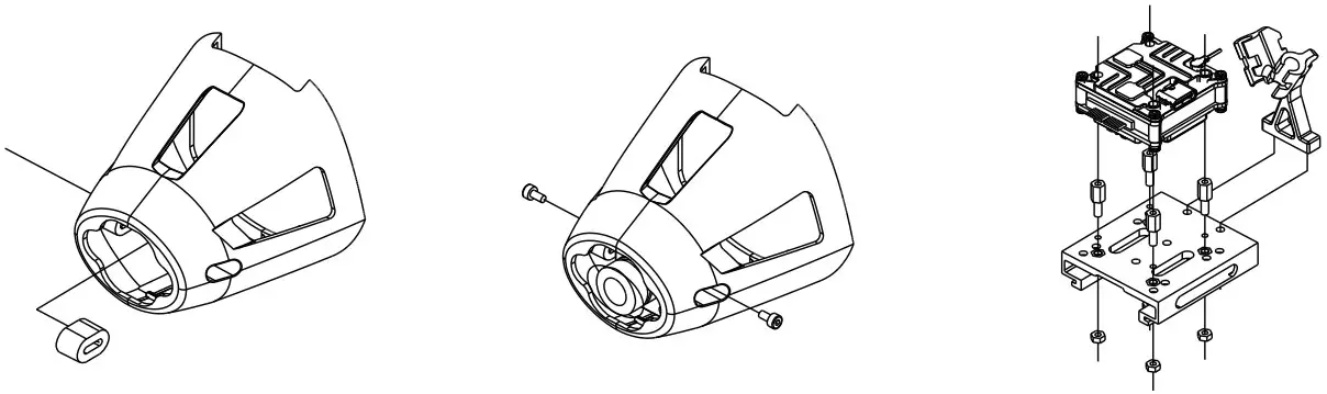
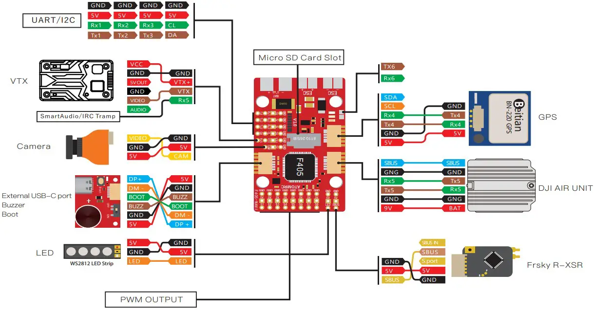
- Install the FC/Receiver

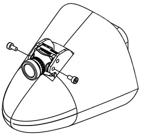
- EPP nose:Analog system

Plastic nose: Digital system
Install the FPV system.
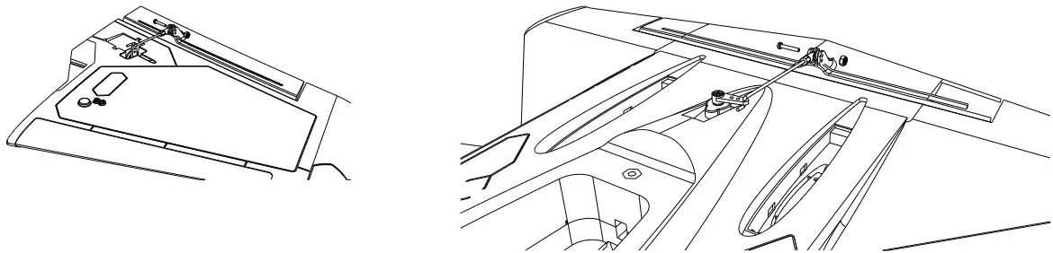
PNP+S、RTH Installation
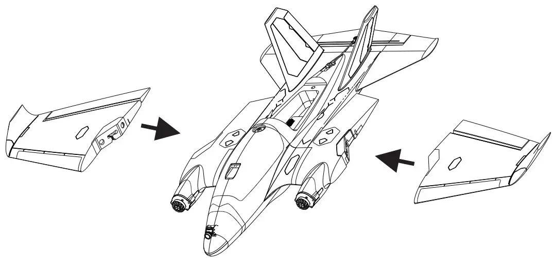
- Install the Wing, Left aileron PWM3 Right wing PWM4.

- Install the INAV configurator then plug to PC

- Install the receiver: CRSF in on UART 2 by default, If using Sbus, please change the UART 2 and receiver protocol

- Install the FPV system, OSD: analog OSD by default, if using digital vtx, user need change the settings on INAV configrator.
- Check I NAV Configurator the receiver type, then assign the channel and mode.

- Latest cli settings, please go to download page of atomrc.com make sure firmware version is matched with the cli settings, reset the flight controller first, then load the cli settings.


Rx2 and SBUS cant use same time, SBUS is on inverted Rx2 If using how power device, suggest solder the capacitor.
Tx800 VTX User manual
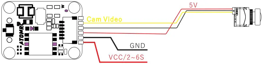
ATOMRC Tx800 VTX Wiring Diagram
VTX Setting
- Hold button 3 second into setting mode.
- In setting mode. short press the button to change band.
- Then hold button 3 seconds into CH setting mode, short press button to change CH.
- Hold button 3 second to get into Power setting mode, there is short bar on LED, short press to switch power, 1 bar means 25mW, 2 bar means 200mW, 3 bar means 500mW.
| Band | Channel | |||||||
| 1 | 2 | 3 | 4 | 5 | 6 | 7 | 8 | |
| Band A | 5865 | 5845 | 5825 | 5805 | 5785 | 5765 | 5745 | 5725 |
| Band B | 5733 | 5752 | 5771 | 5790 | 5809 | 5828 | 5847 | 5866 |
| Band E | 5705 | 5685 | 5665 | 5645 | 5885 | 5905 | 5925 | 5945 |
| Airwave/FS | 5740 | 5760 | 5780 | 5800 | 5820 | 5840 | 5860 | 5880 |
| Race Band | 5658 | 5695 | 5732 | 5769 | 5806 | 5843 | 5880 | 5917 |
| L Band | 5362 | 5399 | 5436 | 5473 | 5510 | 5547 | 5584 | 5621 |
Voltage input: 2~6S Lipo
Power: 100/200/800mw Switchable
Power consumption: 9V 1.1A
Frequency: 5.3~5.9Ghz
ESC Information
Throttle calibration
- The ESC included with the model has a safe If the motor battery is connected to the ESC and the throttle stick is not in the low throttle or off position,the motor will not start untill the throttle stick is moved to the low throttle or off position.
- Power on the ESC(The ESC must connect to the motor and Receiver). The motor will emit a series of beeps, after the beeps, set the the throttle stick the the minimum, the motor will emit a series beep again. now the ESC calibration is done
ATOMRC Exceed BLS 30A 2~4S ESC Wiring Diagram
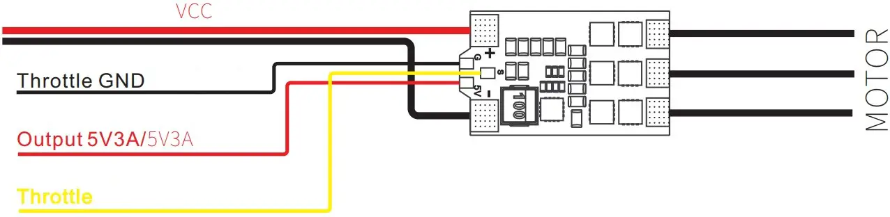
Voltage input: 2~4S Lipo
Max Current: 35A
Output: Built in 5V 3A BEC
Size: 29.5*17.5mm
Please download the latest user manual at www.atomrc.com