Electric Vehicle AC Charger
Instructions
![]() WARNING
WARNING
IMPORTANT SAFETY INSTRUCTIONS
WARNING – This manual contains important instructions for Models:
EVC10 series shall be followed during the installation, operation, and maintenance of the unit.
a) Read all the instructions before using this product.
b) This device should be supervised when used around children.
c) Do not put fingers into the electric vehicle connector.
d) Do not use this product if the flexible power cord or EV cable is frayed, has broken insulation, or any other signs of damage.
e) Do not use this product if the enclosure or the EV connector is broken, cracked, open, or shows any other indication of damage.
f) To reduce the risk of fire, connect only to a circuit provided with branch circuit overcurrent protection in accordance with the CSA C22.1–15 Canadian Electrical.
Code, Part 1 (Canada) or NOM-001-SEDE Electrical installations (utility) (Mexico) or ANSI/NFPA 70 National Electrical Code (USA).
| Circuit Breaker Options table | ||||
| Output Amperage (A) | 16A | 32A | 40A | 48A |
| Circuit Breaker Options (A) | 20A | 40A | 50A | 60A |
g) To avoid a risk of fire or electric shock, do not use this device with an extension cord.
h) THE SUITABILITY OF THE USE OF FLEXIBLE CORD IN ACCORDANCE WITH CE CODE, PART I, RULE 4-012, IS TO BE DETERMINED BY THE LOCAL INSPECTION AUTHORITY HAVING JURISDICTION
i) Risk of electric shock. Do not remove the cover or attempt to open the enclosure. No user-serviceable parts inside. Refer servicing to qualified service personnel.
![]() WARNING
WARNING
This device complies with part 15 of the FCC Rules. Operation is subject to the following two conditions: (1) This device may not cause harmful interference, and (2) this device must accept any interference received, including interference that may cause undesired operation.
Caution: Changes or modifications to this unit not expressly approved by the party responsible for compliance could void the user’s authority to operate the equipment.
Note: This equipment has been tested and found to comply with the limits for a Class A digital device, pursuant to part 15 of the FCC Rules. These limits are designed to provide reasonable protection against harmful interference when the equipment is operated in a commercial environment. This equipment generates, uses, and can radiate radio frequency energy and, if not installed and used in accordance with the instruction manual, may cause harmful interference to radio communications. Operation of this equipment in a residential area is likely to cause harmful interference in which case the user will be required to correct the interference at his own expense.
WIFI module: Contians FCC ID:2AC7Z-ESPWROOM32D
LTE module: Contians FCC ID:XMR202008EC25AFXD
To satisfy FCC RF exposure requirements, a separation distance of 20 cm or more should be maintained between the antenna of this device and persons during device operation.
To ensure compliance, operations at closer to this distance are not recommended.
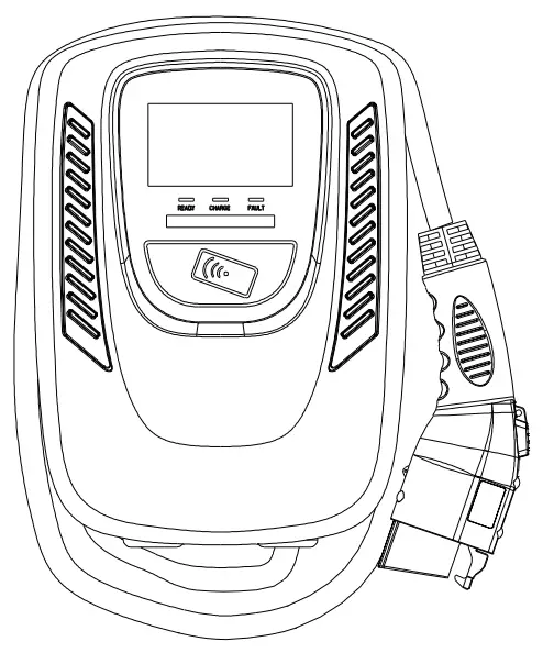
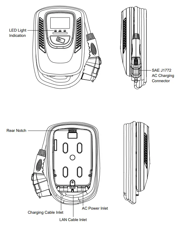
Basic Interface
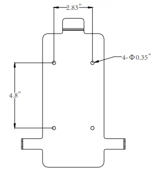
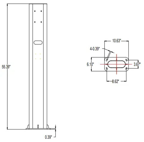
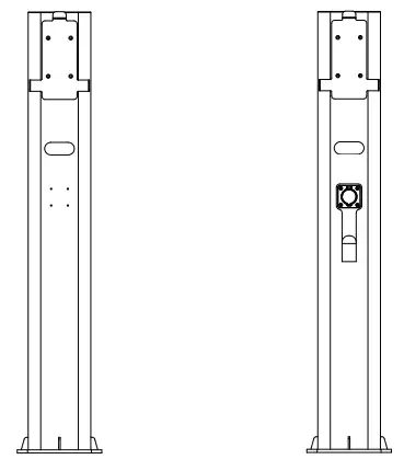
Dimensions
Main Size of Charger
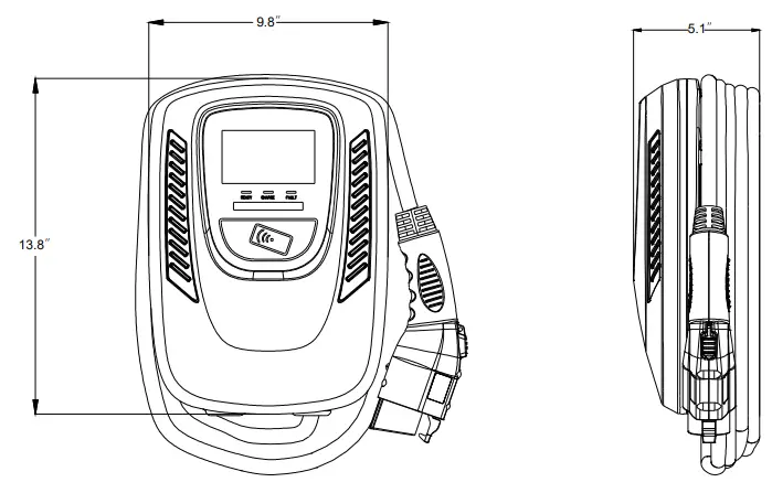
Main Size of Charger
Design Standard
| Safety standards |
| UL2594: Electric Vehicle Supply Equipment |
| UL 2231-1: Personnel Protection Systems for Electric Vehicle (EV) Supply Circuits: General Requirements |
| UL 2231-2: Personnel Protection Systems for Electric Vehicle (EV) Supply Circuits: Particular Requirements for Protection Devices for Use in Charging Systems |
| UL 2251: Plugs, Receptacles, and Couplers for Electric Vehicles |
| UL 62: Flexible Cords and Cables |
| UL 991: Tests for Safety-Related Controls Employing Solid-State Devices |
| UL 1998: Software in Programmable Components |
| NFPA 70 Article 625: National Electrical Code, Electric Vehicle Charging System |
| UL840 (Clearance and Creepage) |
Specification
| Model Name | EVC10 Version |
| Rated Input Voltage | 200-240 VAC / Single Phase |
| Rated Output Current | 16/32/40/48A |
| AC Power Frequency | 60 Hz |
| Input Protection | UVP,OVP,RCD,SPD,Ground Fault Protection |
| Output Protection | OCP, OTP, Control Pilot Fault Protection |
| Output Interface | SAE J1772 AC Charging Connector |
| Storage Temperature | -40°C to + 70°C |
| Operation Temperature | -30°C to +50°C |
| Relative Operation Humidity | 95%RH Maximum |
| Relative Storage Humidity | 95%RH Maximum |
| RFID Authentication | LAN Version or Wi-Fi Version or 4G Version |
| RJ45 Cable Inlet | 10M/100M Base-T |
| Wi-Fi Function*2 | 802.11 b/g/n |
| 4G Fnction*3 | LTE |
| Cable Length | 18FT (From charger’s body to lower edge of charging connector) |
| Protection Level | Type 3 |
| Installation Type | Wall-Mounted |
| Altitude | 2000 m |
| Weight | 6.5±0.5kg |
| Dimensions | 13.8″x9.8″x5.1″ |
| Status Indication | Red, Green, Blue LED |
*1 LAN Version or Wi-Fi Version or 4G Version
*2 Wi-Fi Version
*3 4G Version
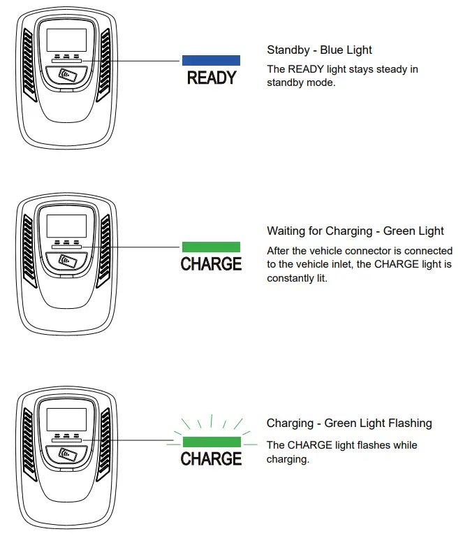
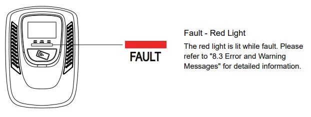
Status Description of the Charger Indication Light
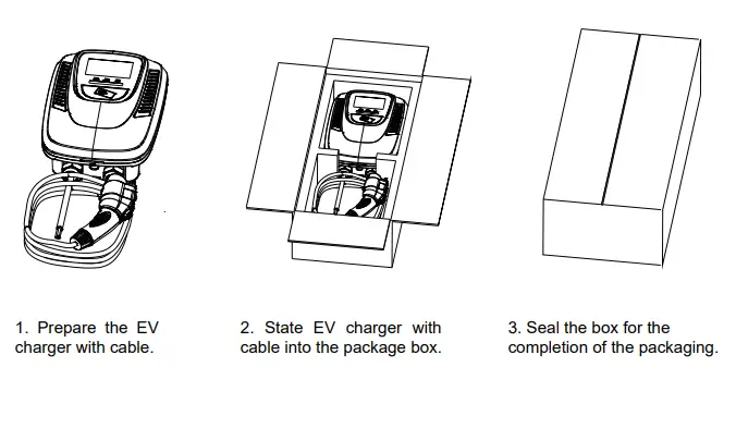
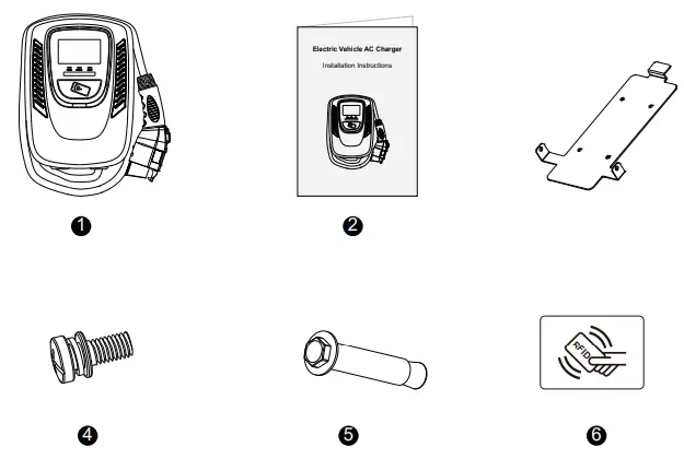
Packing List
Safety Requirements
- Be sure to preview the user manual and ensure local building and electrical codes are reviewed before installing the AC charger.
- The AC charger should be installed by a qualified technician according to the user manual and local safety regulations.
- Use appropriate protection when connecting to the main power distribution cable.
- Type B, C, or D breaker with the rating current for the table should be installed in the upstream AC distribution box.
- Disconnect switch for each ungrounded conductor of AC input shall be provided by others in accordance with the National Electric Code, ANSI/NFPA 70.

NO Product Name Quantity Note 1 AC Charger (With Charging Cable) 1 2 Wall-Mounted Bracket 1 3 User Manual 1 4 M5 teeth screws 2 5 M6 Hexagonal Expansion Screws 4 6 RFID Card (RFID Version Only) 2
Installation Steps
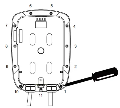
Step1 :
Use a screwdriver to loosen the 11 fixed screws on the rear of the charger, then remove the front cover(for 4G Version).
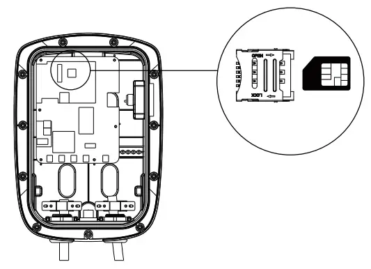
Step2 :
Insert the SIM card according to the picture’s instruction(for 4G Version).
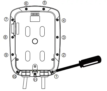
Step3 :
Tighten 11 screws on the front cover after the front cover is put back, the recommended screw torque is 1.0 N.m (9.6 lbs. in)(for 4G Version).
Wiring
GROUNDING INSTRUCTIONS
This product must be grounded. If it should malfunction or break down, grounding provides a path of least resistance for electric current to reduce the risk of electric shock. This product is equipped with a cord having an equipment-grounding conductor and a grounding plug. The plug must be plugged into an appropriate outlet that is properly installed and grounded in accordance with all local codes and ordinances.
WARNING – Improper connection of the equipment-grounding conductor is able to result in a risk of electric shock. Check with a qualified electrician or serviceman if you are in doubt as to whether the product is properly grounded. Do not modify the plug provided with the product – if it will not fit the outlet, have a proper outlet installed by a qualified electrician.
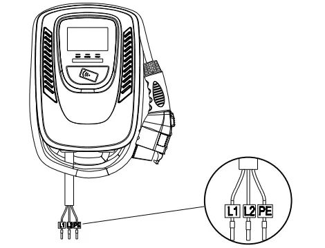
For safe use of electricity, please add circuit breaker protection in the input port of the charging pile. Connect the L1 lead to the grid L1, connect the L2 lead to the grid L2, connect the PE lead to the grid PE(for all Version).
Circuit Breaker Options table
| Output Amperage (A) | 16A | 32A | 40A | 48A |
| Circuit Breaker Options (A) | 20A | 40A | 50A | 60A |
Tools and Materials Required
Tools required before installing the Wall-Mounted charger, gather the following tools:
- Wire stripper
- Crimpers for European terminals
- Phillips screwdriver for M5
- Slotted screwdriver for 4~5.5MM
- Adjustable Wrench M6
- Head gasket screw 10-10.5mm
- Voltmeter or digital multimeter (for measuring AC voltage at the installation site)
The inserting cable should meet the best waterproof performance. It is recommended to use 3 core / 7AWG cable (XLPE or equivalent cable) to pull the cable from the distribution box.
- Level ruler
- Pencil or marker
- Machine drill
Installation Instructions
- “This device shall be mounted at a sufficient height from grade such that the height of the storage means for the coupling device is located between 600 mm (24 inches) and 1.2 m (4 feet) from grade.”
- “This device shall be mounted at a sufficient height from grade such that the height of the storage means for the coupling device is located between 450 mm (18 inches) and 1.2 m (4 feet) from grade.”
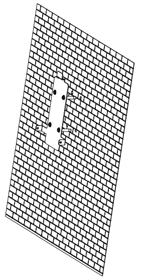
Wall-Mounted Bracket Installation
Step1 :
- Set the positions of the 4 screw holes and drill them, with a diameter of 9mm and a depth of 52mm.
- Use 4 sets of expansion screws and an M6 screw to fix the wall-mounted bracket on the wall.
Step2 :
Align the rear notch of the charger into the wall-mounted bracket and fit the screw holes of the right and left sides.
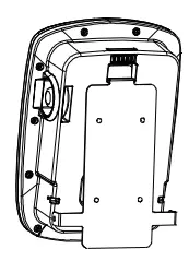
Step3 :
Fix two M5 screws to complete the installation.
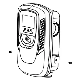
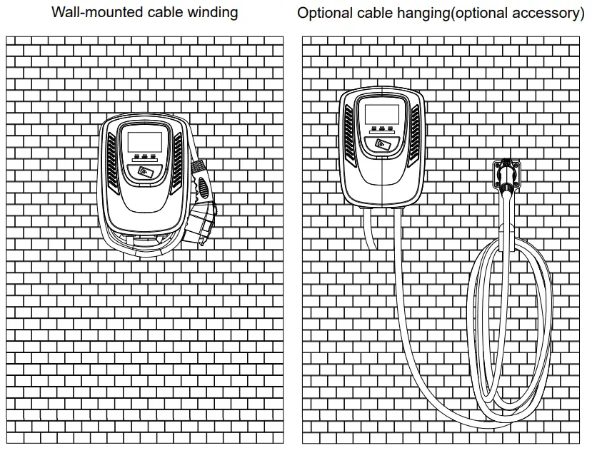
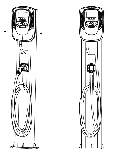
Overall outlook picture after installation:
Wall-Mounted Bracket Installation
STEP1 :
Align the pedestal with the screw holes and lock the pedestal
STEP2 :
- Tighten the panel with 4 M8 screws
- Tighten the hook with 4 M5 screws
STEP3 :
- Hook the charger to the panel and tighten it with 2 M5 screws
- Connect the power cable behind the pedestal
User Maintenance Instructions
Instructions for user maintenance shall include explicit instructions for all cleaning and servicing that are intended to be performed by the user, and shall be preceded by the heading “USER MAINTENANCE INSTRUCTIONS” or the equivalent.
Operating Procedures
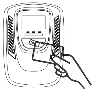
User authorization
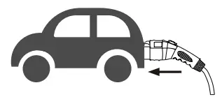
Connect to Vehicle Charging Inlet
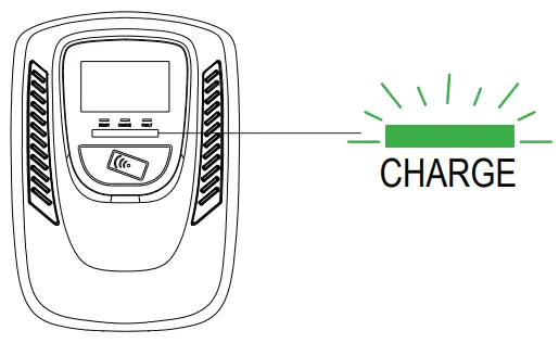
Charging Message
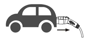
Charging completed
Operating Steps
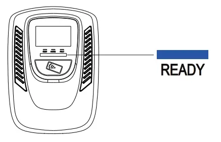
STEP1 / Standby Mode
After power-on,,blue(READY) ,green(CHARGE) and red light (FAULT) all lit. Enter standby mode and the blue light (READY) is steady on. The time from power on to
the green light on is 90 seconds.
STEP2 / Tap the RFID Card
Please plug the charging connector into the vehicle charging inlet. when you tap the RFID card first, needs to complete the insertion of the charging connector within 180
seconds, otherwise you need to tap the RFID card again.
STEP3 / Tap the RFID Card
Tap the RFID card to start the charging.
STEP4 / Charging
The green light (CHARGE) turns to flash automatically, charging is in process
- If the red light (FAULT) is lit, plug in the vehicle connector again.
- If the red light is still lit, please refer to “Error and Warning Messages”.
STEP5 / Charging Finished
When the charging is finished, the blue light (CHARGE) is constantly lit, press the button on the connector to stop the charging.
Error and Warning Message
| Status | Blue | Green | Red | Remark |
| Input OVP | 1 flash followed by 3-sec pause | Auto Recover | ||
| Input UVP | – | 2 flashes followed by a 3-sec pause | Auto Recover | |
| Output OCP | – | 3 flashes followed by a 3-sec pause | Auto Recover | |
| TOP | – | 4 flashes followed by a 3-sec pause | Auto Recover | |
| RCD Abnormal | _ | 5 flashes followed by a 3-sec pause | Auto Recover | |
| Ground Fault | – | 6 flashes followed by a 3-sec pause | Auto Recover | |
| Control Pilot Fault | – | Flicker | Auto Recover | |
| MCU Self-Test Fail | – | Constantly Bright | Contact Customer Service | |
| RCD Self-Test Fail | – | Constantly Bright | Contact Customer Service | |
| Relay Self-Test Fail | – | Constantly Bright | Contact Customer Service | |
| RCD Abnormal Stop Charging | Constantly Bright | Contact Customer Service | ||
| Output OCP Stop Charging | _ | _ | Constantly Bright | Contact Customer Service |
| OTP Stop Charging | _ | Constantly Bright | Contact Customer Service |
Maintenance and Repair
Daily Maintenance
Please keep the charger clean and keep the charger in a clean area with low humidity. Do not install it in an environment near the sea, with high oil, high humidity, or high dust.
- Avoid moisture or water in the charger. If there is water or moisture ingress into the charger, it is necessary to immediately power off to avoid immediate danger and notify the professional personnel to carry out maintenance before the next use.
- If there is any damage or dirt on the vehicle connector, charging cable, or vehicle connector holder, please contact the maintenance personnel immediately.
- Please use the charger properly. Do not hit or press hard on the case. If the case is damaged, please contact a professional technician.
- Avoid placing the charger near hot objects and at high-temperature locations and away from
dangerous substances such as flammable gases and corrosive materials. - Do not place external objects or heavy objects on the charger to avoid danger.
Maintenance Spares
- This charger is equipped with maintenance spares for maintenance use during and over the warranty period. All warranty services and repairs shall be performed by certified service technicians authorized by Joint Technology. For details, please contact your local Joint Technology service partner or directly to our Customer Service. danger.
Warranty and Maintenance
- The warranty period for this charger is three years.
- Any spare parts provided by Joint Technology and used as replacements for repair are covered by a five years guarantee.
- Replacement and repair parts manufactured by alternative manufacturers to those on the maintenance parts are allowed if authorized by Joint Technology.
- After the event of any repair or maintenance under the warranty period, if there is no purchase to extend the warranty service, Joint Technology shall provide a three-month warranty period for any subsequent paid repair work.
- During the warranty period for any malfunction caused by normal use according to the User Manual and Service Instruction (to be determined by certified maintenance technicians of Joint Technology), the product shall be repaired free of charge. Except for the following situations, the charger shall be subject to the above warranty terms:
- The warranty certificate cannot be provided or the contents of the warranty certificate are modified or inconsistent with the label indication of the repaired product.
- Those who are unable to provide valid proof of purchase.
- Those who exceed the manufacturer’s specified warranty period.
- Those who damage the product due to not following the product service instruction for use, maintenance, and storage.
- Damage or malfunction caused by foreign object entering.
- Unauthorized repair, disassembly, or modification.
- Damage caused by force majeure (such as lightning, excessive voltage, earthquake, fire, flood, etc.).
- Malfunction and damage caused by other unavoidable external factors. Malfunction and damage caused by improper use of equipment, such as water or other solutions entering into the equipment.
- Malfunction and damage caused by the grid power supply and voltage which is not specified for use with the charger equipment.
• The above guarantees shall be made solely, and no other express or implied warranties shall be made (including the implied warranties of merchantability, particular and applicable reasonableness and adaptability, etc.) whether, in the contract, civil negligence, or other aspects, the Company shall not be responsible for any special, incidental or consequential damages.
Moving, Transporting, and Storage Instructions
Do not pull input and output cables when you move the charger. Please move the charger with the package. Unboxing the package when you are installing it.