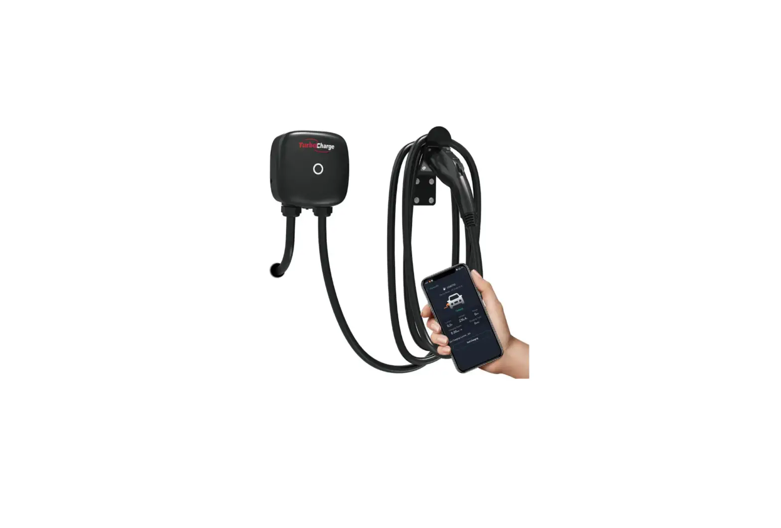
TurboCharge EVC15 Series Electric Vehicle AC Charger User Manual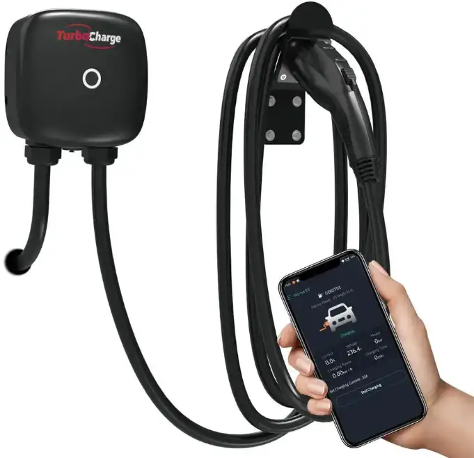
Important Safety Instructions
Overall Warnings & Cautions
WARNING: To avoid fire, injury or death, carefully read and follow the instructions during installation, operation and maintenance.
- DO NOT put fingers into the electric vehicle connector.
- DO NOT use this product if the flexible power cord or EV cable is frayed, insulation-broken, or any other signs of damage.
- DO NOT use this product if the enclosure or the EV connector is broken, cracked, open, or shows any other indication of damage.
- DO NOT remove cover or attempt to open the enclosure because of risk of electric shock.
![]() WARNING: This device should be supervised when used around children.
WARNING: This device should be supervised when used around children.![]() WARNING: This device must be grounded.
WARNING: This device must be grounded.![]() WARNING: To avoid a risk of fire or electric shock, do not use this device with an extension cord.
WARNING: To avoid a risk of fire or electric shock, do not use this device with an extension cord.![]() WARNING: The suitability of the use of flexible cord in accordance with CE code, part I, rule 4-012, is to be determined by the local inspection authority.
WARNING: The suitability of the use of flexible cord in accordance with CE code, part I, rule 4-012, is to be determined by the local inspection authority.![]() WARNING: To reduce the risk of fire, connect only to a circuit provided branch circuit over-current protection in accordance with the CSA C22.1–15 Canadian Electrical Code, Part 1 (Canada) or NOM-001-SEDE Electrical installations (utility) (Mexico) or ANSI / NFPA 70 National Electrical Code (USA).
WARNING: To reduce the risk of fire, connect only to a circuit provided branch circuit over-current protection in accordance with the CSA C22.1–15 Canadian Electrical Code, Part 1 (Canada) or NOM-001-SEDE Electrical installations (utility) (Mexico) or ANSI / NFPA 70 National Electrical Code (USA).
| Circuit Breaker Options table | ||||
| Output Amperage (A) | 16A | 32A | 40A | 48A |
| Circuit Breaker Options (A) | 20A | 40A | 50A | 60A |
![]() WARNING & CAUTION
WARNING & CAUTION
Installation Requirements
![]() WARNING: Disconnect electrical power prior to installing the charging station.
WARNING: Disconnect electrical power prior to installing the charging station.![]() WARNING: Be sure to preview the user manual and ensure local building and electrical codes are reviewed before installing the AC charger.
WARNING: Be sure to preview the user manual and ensure local building and electrical codes are reviewed before installing the AC charger.![]() WARNING: The AC charger should be installed by a qualified technician according to the user manual and local safety regulations.
WARNING: The AC charger should be installed by a qualified technician according to the user manual and local safety regulations.![]() CAUTION: Use appropriate protection when connecting to the main power distribution cable.
CAUTION: Use appropriate protection when connecting to the main power distribution cable.![]() CAUTION: Type B, C or D breaker with the rating current for table should be installed in the upstream AC distribution box.
CAUTION: Type B, C or D breaker with the rating current for table should be installed in the upstream AC distribution box.![]() CAUTION: Disconnect switch for each ungrounded conductor of AC input shall be provided by others in accordance with the National Electric Code, ANSI/NFPA70.
CAUTION: Disconnect switch for each ungrounded conductor of AC input shall be provided by others in accordance with the National Electric Code, ANSI/NFPA70.![]() CAUTION: The device shall be mounted at height between 2 feet (600 mm) and 4 feet (1200 mm) from ground.
CAUTION: The device shall be mounted at height between 2 feet (600 mm) and 4 feet (1200 mm) from ground.![]() CAUTION: Please keep the charger in a clean area with low humidity. Not recommended to be installed in coastal environments with high humidity or high dust.
CAUTION: Please keep the charger in a clean area with low humidity. Not recommended to be installed in coastal environments with high humidity or high dust.
Daily Maintenance
![]() CAUTION: Avoid moisture or water in the charger. If there is water or moisture ingress in the charger, it is necessary to immediately power off to avoid immediate danger, and notify the professionals to carry out maintenance before next use.
CAUTION: Avoid moisture or water in the charger. If there is water or moisture ingress in the charger, it is necessary to immediately power off to avoid immediate danger, and notify the professionals to carry out maintenance before next use.![]() CAUTION: Please use the charger properly. Do not hit or press hard on the enclosure. If it is damaged, please contact a professional technician.
CAUTION: Please use the charger properly. Do not hit or press hard on the enclosure. If it is damaged, please contact a professional technician.![]() CAUTION: Avoid placing the charger near hot objects and at high temperature locations and away from dangerous substances such as flammable gases and corrosive materials.
CAUTION: Avoid placing the charger near hot objects and at high temperature locations and away from dangerous substances such as flammable gases and corrosive materials.![]() CAUTION: Do not put heavy objects on the charger to avoid danger.
CAUTION: Do not put heavy objects on the charger to avoid danger.
Product Introductions
CAUTION: Avoid placing the charger near hot objects and at high temperature locations and away from dangerous substances such as flammable gases and corrosive materials.
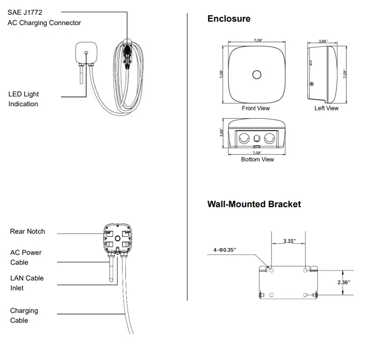
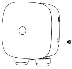
Basic Interface/Basic Dimension
Specifications
| Model Number | EVC15 |
| Rated Input Voltage | 200-240 VAC |
| Rated Output Current | 16/32/40/48A |
| AC Power Frequency | 60 Hz |
| Input Protection | UVP, OVP, RCD, SPD, Ground Fault Protection |
| Output Protection | OCP, OTP, Control Pilot Fault Protection |
| Output Interface | SAE J1772 AC Charging Connector |
| Storage Temperature | -40°F to 158°F |
| Operation Temperature | -22°F to 122°F |
| Relative Operation Humidity | 95% RH Maximum |
| Relative Storage Humidity | 95% RH Maximum |
| RFID Authentication | LAN Version / Wi-Fi Version |
| RJ45 Cable Inlet*1 | 10M / 100M Base-T |
| Wi-Fi Function*2 | 802.11 b/g/n |
| Cable Length | 18ft |
| Protection Level | Type 3 |
| Installation Type | Wall-Mounted |
| Altitude | ≤ 6561ft |
| Status Indication | Red, Green, Blue LED |
LAN ersion or Wi- i ersion
Wi- i ersion
Design Standards
UL 2594: Electric Vehicle Supply Equipment
UL 2231-1: ULPrersonnel Protection Syste
ms forElectric Vehicle (EV) Supply Circuits:
General Requirements
UL 2231: Personnel Protection Systems for
Electric Vehicle (EV) Supply Circuits:
Particular Requirements for Protection
Devices for Use in Charging Systems
UL 2251: Plugs, Receptacles and Couplers
for Electric Vehicles
UL 62: Flexible Cords and Cables
UL 991: Tests for Safety-Related Controls
Employing Solid-State Devices
UL 1998: Software in Programmable
Components
NFPA 70 Article 625: National Electrical
Code, Electric Vehicle Charging System
UL 840 (Clearance and Creepage)
Verify Contents
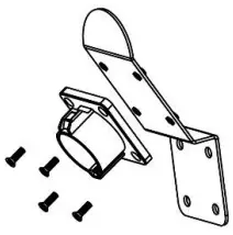
Check the box to ensure you have this installation guide and these parts:
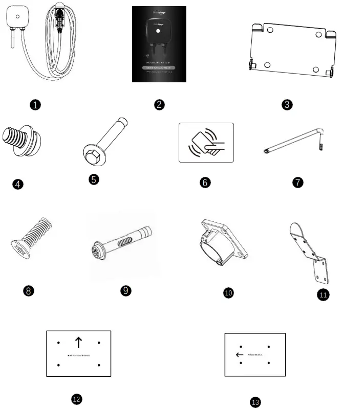
| No. | Product Name | Quantity | Description |
| 1 | AC Charger | 1 | With attached input power cable and output charging cable |
| 2 | User Manual | 1 | PDF version available online |
| 3 | Wall-Mounted Bracket | 1 | For mounting the charging station to the wall/structure |
| 4 | M5 Anti-Theft Round Head Screws | 2 | For securing the charging station to the Mounting Bracket |
| 5 | M6 Hexagonal Expansion Screws | 4 | For installing the Mounting Bracket to the wall/structure |
| 6 | RFID Card | 2 | RFID Version Only |
| 7 | Allen Wrench | 1 | For tightening M5 Screws |
| 8 | M5 Anti-Theft Countersunk Head Screws | 4 | For securing the Plug Holster to the Holster Bracket |
| 9 | M6 Anti-Theft Hexagonal Expansion Screws | 4 | For installing the Holster Bracket to the wall/structure |
| 10 | Plug Holster | 1 | For allowing the plugs to be neatly and safely stored when not in use. |
| 11 | Holster Bracket | 1 | For mounting the Plug Holster to the wall/structure |
| 12 | Corrugated Mounting Template | 1 | For easy drilling of 4 screws holes for wall-mounted bracket. |
| 13 | Corrugated Mounting Template | 1 | For easy drilling of 4 screws holes for holster bracket. |
Note: If you are missing any of these parts, please contact us @ 877-960-5408 or [email protected]
Gather Tools
Tools required before installing the Wall-Mounted charger, gather the following tools:
- Wire stripper
- Adjustable Wrench M6
- Voltmeter or digital multi-meter (for measuring AC voltage at the installation site)
- Level
- Pencil or marker
- Drill
- The inserting cable should meet the best waterproof performance. It is recommended to use 3 core /7AWG cable (XLPE or equivalent cable) to pull the cable from the distribution box.
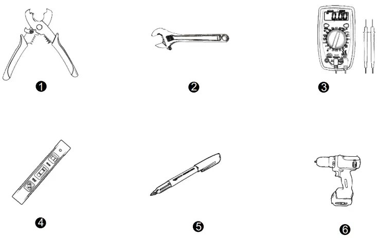
Note: The above tools are very important, please gather them all.
Plan The Mounting
WARNING: In areas with frequent thunderstorms, add surge protection at the service panel for all circuits. Ensure all power and ground connections, especially those at the breaker and bus bar, are clean and tight.
CAUTION: Not recommended to be installed in coastal environments with high humidity or high dust.
STEP 1
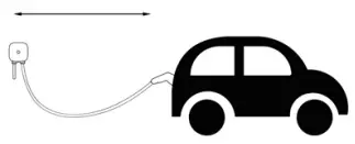
Select the appropriate mounting location with electrical capacity:
I. Ensure the owner has chosen a mounting location that allows the charging cable to reach the car’s charging port while still providing slack.
II. The device must be anchored into mounting such as 2” x 4” stud or a solid wall.
III. The device shall be mounted at height between 2 feet (600 mm) and 4 feet (1200 mm) from ground.
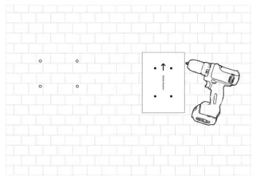
STEP 2
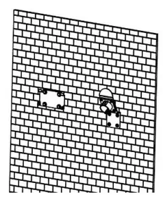
Drill 8 Screw Holes with a diameter of 0.35” and a depth of 2.05” by using 2 mounting templates. Please drill screw holes in the direction of the template arrow. And use two templates at a horizontal distance around 12 feet.
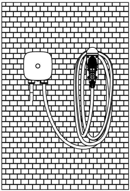
Mount the Charging Station
STEP 3
Secure the Plug Holster to the Holster Bracket with 4 M5 Anti-theft countersunk head screws. Please ensure the grooved part of the inner ring is always downward.
STEP 4
Use 2 different sets (8 pcs in total) of Hexagonal Expansion Screws to secure the wall-mounted bracket and holster bracket (use anti-theft hexagonal expansion screws) on the wall. Then level the brackets.
STEP 5
Align the rear notch of charger with the wall-mounted bracket and fit the screw holes of the right and left side.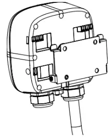
STEP 6
Tighten two M5 anti-theft screws to complete the installation.
Wire The Circuit
![]() WARNING: This device must be grounded. Disconnect electrical power prior to installing the charging station
WARNING: This device must be grounded. Disconnect electrical power prior to installing the charging station
![]() WARNING: Improper connection of the equipment-grounding conductor would result in a risk of electric shock. Check with a qualified electrician or serviceman if you are not sure whether the product is properly grounded. Do not modify the plug provided with the product – if it doesn’t fit the outlet, have a proper outlet installed by a qualified electrician
WARNING: Improper connection of the equipment-grounding conductor would result in a risk of electric shock. Check with a qualified electrician or serviceman if you are not sure whether the product is properly grounded. Do not modify the plug provided with the product – if it doesn’t fit the outlet, have a proper outlet installed by a qualified electrician
![]() CAUTION: Use appropriate protection when connecting to the main power distribution cable.
CAUTION: Use appropriate protection when connecting to the main power distribution cable.
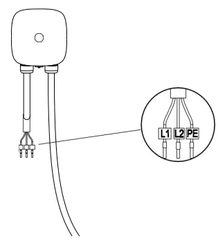
STEP 7
For safe use of electricity, please set circuit breaker protection in the input part of E Charger.
The wiring is not complicated, just need to follow the instructions below:
Connect the L1 lead to the grid L1, connect the L2 lead to the grid L2, connect the PE lead to the grid PE.
Operate Your Device
![]() WARNING: This device should be supervised when used around children.
WARNING: This device should be supervised when used around children.
![]() CAUTION: Please use the charger properly. Do not hit or press hard on the enclosure. If the case is damaged, please contact a professional technician.
CAUTION: Please use the charger properly. Do not hit or press hard on the enclosure. If the case is damaged, please contact a professional technician.
![]() CAUTION: Do not put heavy objects on the charger to avoid danger.
CAUTION: Do not put heavy objects on the charger to avoid danger.
Operating Steps with Plug and Charge
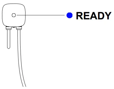
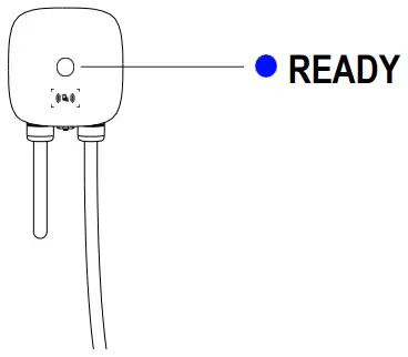
STEP 1
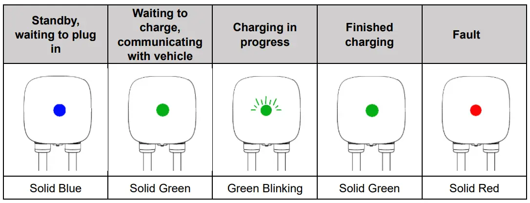
Standby Mode: After being powered on, the lights will be all on, blue light (READY), green light (CHARGE) and red light ( AULT). Then the blue light (READY) is constantly on in standby mode.
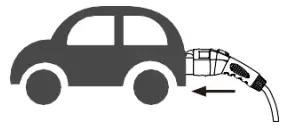
STEP 2
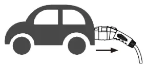
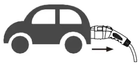
Plug the Charging Connector:
Please plug the charging connector into the vehicle charging inlet.
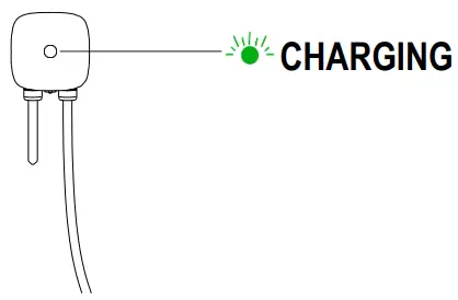
STEP 3
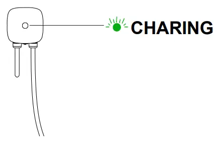
Charging: The green light (CHARGE) turns to flash automatically, charging is in process.
If the red light ( AULT) is on, plug the vehicle connector again.
If red light is still on, please refer to “Error and Warning Messages”.
STEP 4
Charging finished: When the charging is finished, the green light (CHARGE) is constantly on, please press the button on connector and pull out the charging connector.
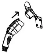
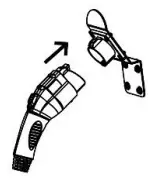
STEP 5
Re-plug the charging connector: when you finish the charging process, please re-plug the charging connector back to the holster, you will hear a “click” sound.
Operating Steps with R ID
CAUTION: Please keep your RFID card properly to avoid unnecessary loss.
STEP 1
Standby Mode: After power-on, blue light (READY), green light (CHARGE) and red light ( AULT) all on. The blue light (READY) is constantly on when in standby mode.
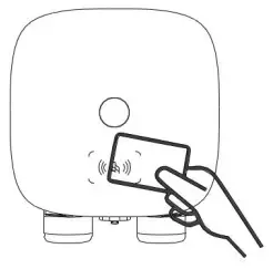
STEP 2
Swipe the RFID Card:
Please plug the charging connector into the vehicle charging inlet. Swipe the R ID card first and plug in the charging connector within 120 seconds, otherwise you need to swipe the R ID card again.
STEP 3
Charging: The green light (CHARGE) turns to flash automatically, charging is in process.
If the red light ( AULT) is on, plug in the charging connector again.
If red light is still on, please refer to “Error and Warning Messages”.
STEP 4
Charging finished: When the charging is finished, the green light (CHARGE) is constantly on, please press the button on connector and pull out the charging connector
STEP 5
Re-plug the charging connector: when you finish the charging process, please re-plug the charging connector back to the holster, you will hear a “click” sound.
Light Codes
After Start UP
Error and Warning Messages
| Status | Red | Remark |
| Input OVP | 1 flash followed by 3 sec pause | Auto Recover |
| Input UVP | 2 flashes followed by 3 sec pause | Auto Recover |
| Output OCP | 3 flashes followed by 3 sec pause | Auto Recover |
| OTP | 4 flashes followed by 3 sec pause | Auto Recover |
| RCD Abnormal | 5 flashes followed by 3 sec pause | Auto Recover |
| Ground Fault | 6 flashes followed by 3 sec pause | Auto Recover |
| Control Pilot Fault | Flicker | Auto Recover |
| MCU Self-Test Fail | Constantly Bright | Contact Customer Service |
| RCD Self-Test Fail | Constantly Bright | Contact Customer Service |
| Relay Self-Test Fail | Constantly Bright | Contact Customer Service |
| RCD Abnormal Stop Charging | Constantly Bright | Contact Customer Service |
| Output OCP Stop Charging | Constantly Bright | Contact Customer Service |
| OTP Stop Charging | Constantly Bright | Contact Customer Service |
Smart APP Guide (Optional)
Download Home EV app.

Follow the tutorial in APP to connect your device.
FCC Statement
This device complies with part 15 of the FCC Rules.
Operation is subject to the following two conditions:
This device may not cause harmful interference, and this device must accept any interference received, including interference that may cause undesired operation
Caution: Changes or modifications to this unit not expressly approved by the party responsible for compliance could void the user’s authority to operate the equipment.
Note: This equipment has been tested and found to comply with the limits for a Class A digital device, pursuant to part 15 of the FCC Rules. These limits are designed to provide reasonable protection against harmful interference when the equipment is operated in a commercial environment. This equipment generates, uses, and can radiate radio frequency energy and, if not installed and used in accordance with the instruction manual, may cause harmful interference to radio communications. Operation of this equipment in a residential area is likely to cause harmful interference in which case the user will be required to correct the interference at his own expense.
WIFI module: Contains FCC ID:2AC7Z-ESPWROOM32D
To satisfy FCC RF exposure requirements, a separation distance of 20cm or more should be maintained between the antenna of this device and persons during device operation. To ensure compliance, operations at closer than this distance is not recommended.\
Warranty and Maintenance
- The warranty period for this charger is two years.
- During the warranty period for any malfunction under normal use according to the
User Manual and Service Instructions (to be determined by certified maintenance technicians of sellers), the product shall be repaired free of charge. Except for the following situations, the charger shall be subject to the above warranty terms:
- The warranty certificate cannot be provided or the contents of the warranty certificate are modified or inconsistent with the label indication of the repaired product.
- Those who are unable to provide valid proof of purchase.
- Those who exceed the manufacturer’s specified warranty period.
- Those who damage the product due to not following the product service instruction for use, maintenance and storage.
- Damage or malfunction caused by external object entering.
- Unauthorized repair, disassembly or modification.
- Damage caused by force majeure (such as lightning, excessive voltage, earthquake, fire, flood, etc.).
- Malfunction and damage caused by other unavoidable external factors. Malfunction and damage caused by improper use of equipment, such as water or other solutions entering into the equipment.
- Malfunction and damage caused by the grid power supply and voltage which is not specified for use with the charger equipment.
The above guarantees shall be made solely, and no other express or implied warranties shall be made (including the implied warranties of merchant ability, particular and applicable reason- ableness and adaptability, etc.) whether in the contract, civil negligence, or other aspects, the Company shall not be responsible for any special, incidental or consequential damages.


 Charger User Manual")


