COTEK CE-R1 DC Power System Remote Control
Overview
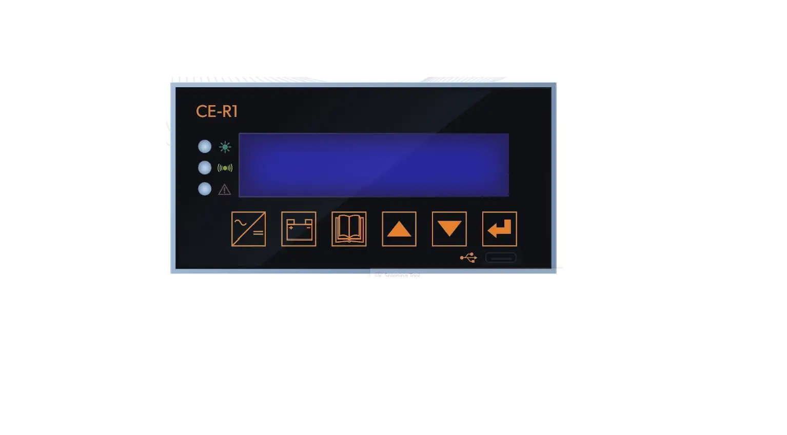
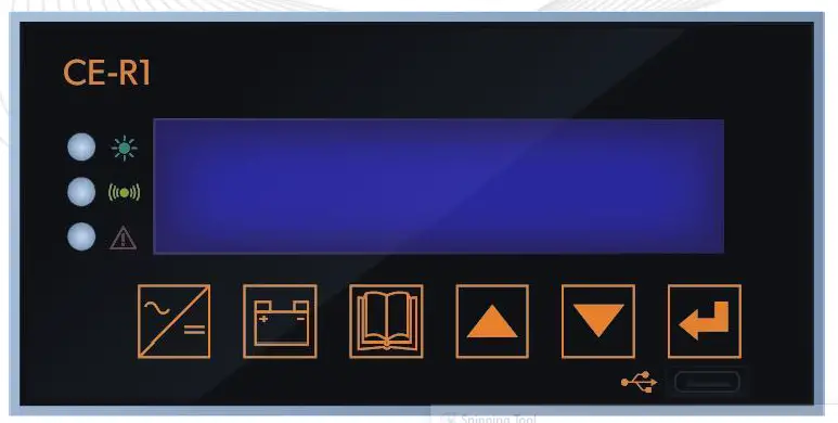
CE-R1 is a Central Control Unit for controlling and monitoring DC power system.
The package includes:
- CE-R1
- User Manual
The CE-R1 is equipped with the following features :
- LED Indicator
The LED provides the DC power system statuses in a straightforward way. - LCD Display
LCD Display – The LCD display is a 16 x 4 line alphanumeric display used for setting up the DC power system operation , as well as viewing current status or fault messages. - Function Buttons
Click buttons allows you to select a menu item or to save a setting, once it is displayed on the LCD screen.
Introduction
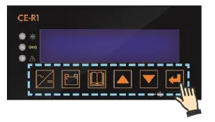
Front Panel
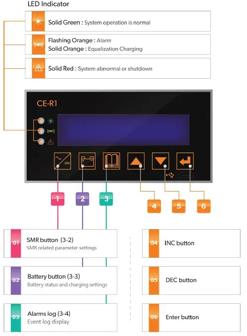
Basic operation instructions
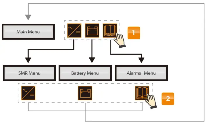
- Press SMR / Battery / Alarms log buttons to enter each sub-menu.
- Press SMR / Battery / Alarms log buttons again to return to main menu
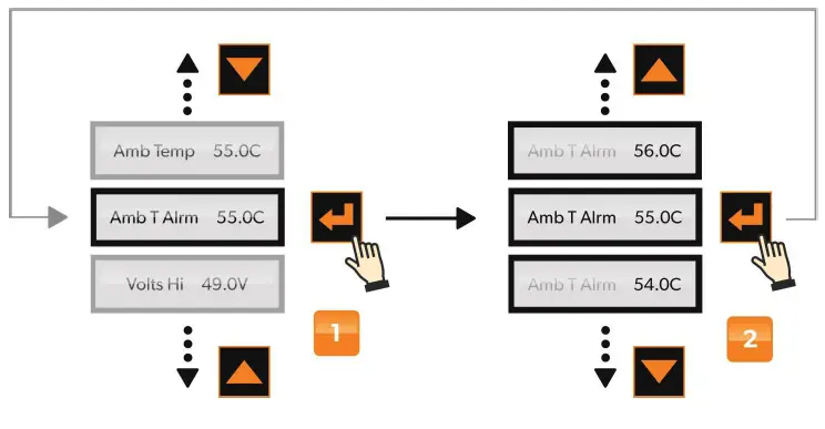
- In each sub-menu, press Enter button 3 sec. to enter detailed setting for each items.
- After selecting desired value, press Enter button again to confirm setting value
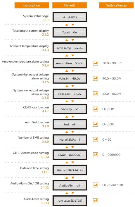
- System Status Page
To indicate system output current to Load only and charging stage - Total Output Current Display
To indicate total current output to loads and battery. - Ambient Temperature Display
To indicate ambient temperature measured by temperature sensor - Ambient Temperature Alarm Setting
To set ambient temperature alarm trigger point - System High Output Voltage Alarm Setting
To set high output voltage alarm trigger point for all system - System Low Output Voltage Alarm Setting
To set low output voltage alarm trigger point for all system - CE-R1 Lock Function
To lock/unlock CE-R1 function buttons - Auto Test Function
To self-test SMR and Central Control Unit, which displays Firmware version (1st page) and flashing pixel page (2nd page) - Number of SMR Setting
To input SMR numbers that are installed in the system, in order for precise control and parameters calculation - CE-R1 Access Code Naming
To provide unique identity code for Central Control Units if there are more than one control units installed - Date and Time Setting
To set system date and time, which is used for event log recording - Audio Alarm On/Offsetting
To turn Audio alarm On/Off, and warning alarm on LED & LCD remain constant when this function is turned off - Alarm Level Setting
To set each alarm as Major/Minor alarm, which can trigger front panel alarm relays separately. By this setting, the user can choose to assign an alarm level for the below fault conditions according to user’s design concept.
- Major alarm
- Minor alarm
- “No Logo” – Regular alarm
Item | Item Alarm Level | LED Display* | Description |
| 1 | EEPROM Fault CSU | A | CE-R1 EEPROM fault |
| 2 | SMR Alarm | A | SMR alarm |
| 3 | Cct Breaker | A | Fuse/Breaker is Open |
| 4 | LVDS Open | A | Low Voltage Disconnect is Open |
| 5 | Voltage High | A | System output voltage is over voltage |
| 6 | Voltage Low | A | System output voltage is under voltage |
| 7 | Battery Disch | A | Battery is discharging |
| 8 | SMR Comms Fail | A | SMR communication fails |
| 9 | AC Volt Fault | A+R | AC input voltage is abnormal |
| 10 | Amb Temp High | A | Ambient temperature is too high |
| 11 | Batt Temp High | A | Battery temperature is too high |
| 12 | Batt I-Limit | A | Battery charging current is limited |
| 13 | Bat Sym Alarm | A | Discharging current deviation |
| 14 | MOVB Fail | A | Metal Oxide Varistor Board fails |
| 15 | MS OFF or TRIP | A | Main switch is open or trip |
| 16 | SMR HVSD | A+R | SMR High Voltage shutdown |
| 17 | Battery Switch | A | Battery switch is open |
| 18 | Batt Temp Sens | A | Battery temperature sensor is disconnected |
| 19 | UNCAL SMR | A | SMR current sharing unbalance |
| 20 | SMR Range | A | Any setting parameter is out of range for SMR |
| 21 | Bat Disch Low | A | Battery discharge low voltage |
| 22 | Disch Tst Fail | A | Battery discharge test fail |
| 23 | SMR Fault | A / A+R | SMR fault |
LED Display
A : Amber LED flashing
R : Red LED solid
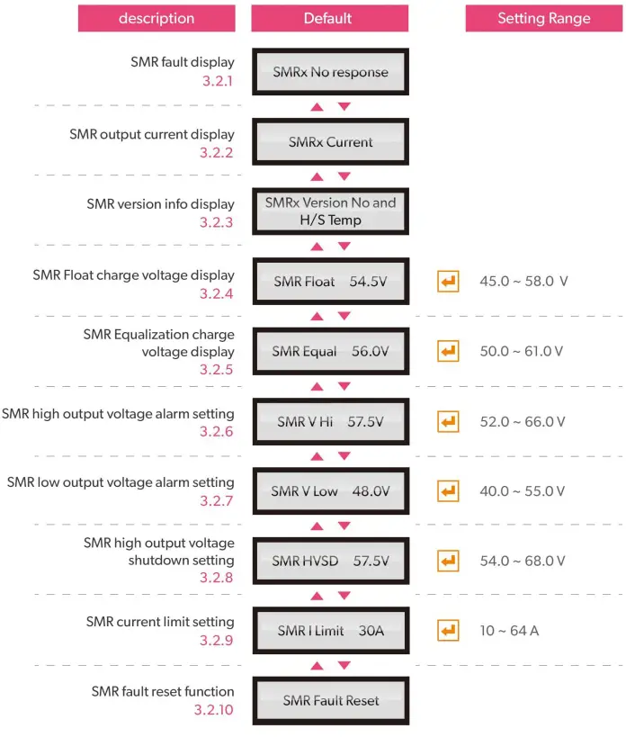
- SMR Fault Display
To indicate the faulty condition when SMR is not disconnected or is switched off - SMR Output Current Display
To indicate each SMR’s current output - SMR Version Info Display
To indicate indivisual SMR firmware version and heat sink temperature - SMR Float Charge Voltage Display
The float charge voltage is set in “Battery” Menu and only displayed here for quick reference - SMR Equalization Charge Voltage Display
The Equalization charge voltage is set in “Battery” Menu and only displayed here for quick reference - SMR High Output Voltage Alarm Setting
To set SMR high output voltage alarm trigger point - SMR Low Output Voltage Alarm Setting
To set SMR low output voltage alarm trigger point - SMR High Output Voltage Shutdown Setting
To set SMR high output voltage shutdown trigger point - SMR Current Limit Setting
To limit all SMR output current value - SMR Fault Reset Function
This function will reset and activate any single SMR which is locked by protection (such as HVSD)
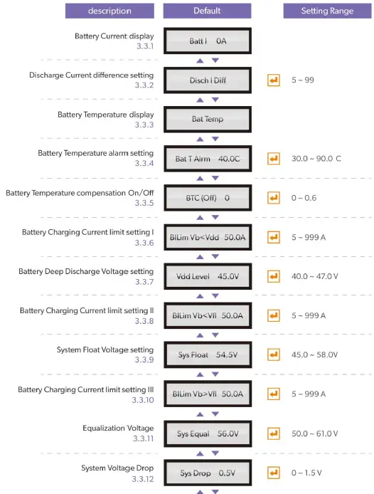
- Battery Current Display
There are 2 conditions: (1)Charging: BattX XXA (2)Discharge: BattX XXA DIS - Discharge Current Difference Setting
When Batteries are supplying the loads (discharging), this value can be set to alert di scharging current difference between batteries is over the value (in Amp) - Battery Temperature Display
To display battery temperature when battery temperature sensor is installed - Battery Temperature Alarm Setting
To set battery temperature alarm trigger point - Battery Temperature Compensation On/Off
To switch On/Off Battery Temperature compensation function. The range is from 0.1 to 0.6 mV/C/Cell(mV/ ˚C /Per - Battery Charging Current Limit Setting I
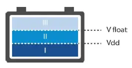
Battery Charging Current Limit setting I is applicable when battery voltage is below Vdd (Deep Discharge Voltage) and sets the maximum current that flows into the batteries batteries. - Battery Deep Discharge Voltage Setting
To set battery deep discharge voltage value - Battery Charging Current Limit Setting II
Battery Charging Current Limit setting II is applicable when battery voltage is between Vdd (Deep Discharge Voltage) and Float Voltage (Vfl), and sets the maximum current that flows into the batteries. - System Float Voltage Setting
To set the system output voltage at the output busbar terminals - Battery Charging Current Limit Setting III
Battery Charging Current Limit setting III is applicable when battery voltage is above Float Voltage(Vfl), which is applicable when batteries are - Equalization Voltage
To set maximum voltage reached during equalization of the batteries
- System Voltage Drop
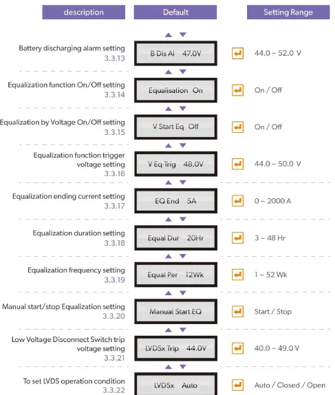
To set the maximum voltage difference that indivisual SMR can surpass programmed System Float voltage, in order to compensate for the voltage loss due to output connector, relay and busbars of the system. - Battery Discharging Alarm Setting
To set an alarm trigger voltage when batteries are being discharged - Equalization Function On/Off Setting
To turn On/Off the Equalization function. If turned off, all Equalization sub pages will be hidden. - Equalization by Voltage On/Off Setting
To initialize Equalization by voltage level V when battery is discharging - Equalization Function Trigger Voltage Setting
To set Equalization function trigger voltage - Equalization Ending Current Setting
To set the output current level upon which Equalization ends - Equalization Duration Setting
To set the maximum duration for Equalization - Equalization Frequency Setting
To set a cyclical Equalization charging, say 12 weeks
If Equalization charging is activated anytime during 12 weeks, it will count another 12 weeks before next Equalization charging takes place - Manual Start/Stop Equalization Setting
To start/stop Equalization charging manually. If Equalization is stopped manually, it goes to float
charging mode. - Low Voltage Disconnect Switch Trip Voltage Setting
To set Low Voltage Disconnect Switch trip voltage in order to protect battery from deep discharged when AC power outage is too long. - To set LVDS Operation Condition
To set LVDS operation- Auto: LVDS opens when trip voltage point is reached
- Closed: to close LVDS manually
- Open: to open LVDS manually
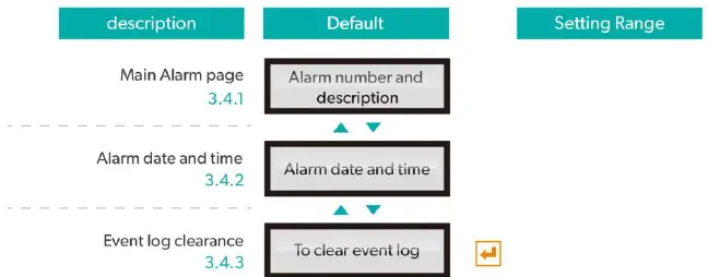
- Main Alarm page
To display the most recent alarm log. “1” is the latest alarm item, followed by incremental Number ( 3…) - Alarm date and time
To display alarm date and time following each alarm item in “Main alarm page” - Event log clearance
To clean all event logs stored in Central Control Unit (CE R1)
System Trouble Shooting Guide
Main Menu warning: Below warning messages will display in Main Menu level.
| Alarm Condition | Possible Cause | Action Suggested |
| 1. SMR Alarm | Any problem with one or more SMRs | Check SMRs |
| SMRs are not sharing correctly | Check SMRs or communication cables | |
| 2. Equalize Mode | Automatic cycle in progress due to recent AC power failure | No action required |
| Automatic Periodic Equalize cycle in progress | Check CE-R1 if system is in AUTO or MANUAL mode -If in AUTO mode, display will show remaining Equalize time. Check log for previous cycle date. If cycle too early, replace CE-R1 | |
| Manual initiation of Equalize cycle | Check Operator log; in BATT menu, scroll to “Manual Stop EQ” screen and press ENTER to terminate cycle if necessary | |
| 3. SMR Urgent | All SMRs are off due to AC power failure | If possible restore AC power |
| One or more SMRs are off due to faults; | Check Individual SMRs for obvious problem; replace SMRs if necessary | |
| All SMRs are off due to incorrect Inhibit signal from CE-R1 | Replace CE-R1 | |
| One or more SMRs in Current Limit | Check Current Limit settings and adjust if necessary; or batteries being recharged | |
| 4. Cct Breaker | Fuse or CB within PDU has blown or tripped | Check PDU (Power Distribution Unit) |
| Wire or connector loose on MUIB | Check MUIB connections and tighten | |
| 5. Battery Switch | Any one of 2 battery switches is open | Close if appropriate |
| Bad connection to MUIB | Repair connection | |
| 6. Amb Temp High | Ambient Temperature is too high | Reduce temperature by force colling, say fans |
| Temperature sensor is faulty | Check and replace if necessary | |
| Connection to MUIB is faulty | Repair connection | |
| 7. Batt Temp High | One of the 2 battery sensors is reporting temperature higher than preset level | Check battery temperatures and if necessary increase ventilation and cooling |
| Set point is too low | Check Batt Temp High threshold level and re-adjust if necessary | |
| Temperature Sensor in CE-R1 not | Plug in temperature sensor if required; |
| attached or faulty | Replace temperature sensor | |
| Faulty MUIB connection(s) | Replace MUIB | |
| Faulty CE-R1 | Replace CE-R1 | |
| 8. LVDS Open | Battery discharged to the limit voltage level due to no AC power | Check AC voltage and reset if possible |
| Battery voltage OK, and CE-R1 faulty | Replace CE-R1 | |
| Battery voltage OK, and CE-R1 faulty | Replace CE-R1 | |
| LVDS threshold level is too high | Reset level in BATT menu | |
| 9. Voltage High | Volts High level in CE-R1 is too low | Reset level to correct value |
| Temperature compensation coefficient setting is too high | Set correct temperature compensation coefficient | |
| Faulty MUIB or CE-R1 | Replace MUIB or CE-R1 | |
| 10. Voltage Low | Volts Low threshold in CE-R1 setting is too high | Reset level to correct value |
| Temperature compensation coefficient setting is too high | Set correct temperature compensation coefficient | |
| Faulty MUIB or CE-R1 | Replace MUIB or CE-R1 | |
| 11. Battery Disch | Output voltage low due to SMRs off | Check AC voltage and restore if possible; |
| Float level set too low | Set float level to correct value | |
| Battery Disch level set too high | Set correct Battery Disch level | |
| Faulty control loop in CE-R1 | Replace CE-R1 | |
| 12. SMR Comms Fail | Comms cable faulty | Replace cable |
| Faulty MUIB or CE-R1 | Replace CE-R1 | |
| 13. AC Volt Fault | AC voltage out of tolerance | Check AC voltages and fix if possible |
| AC voltage threshold levels incorrect | Set correct levels | |
| Faulty AC monitoring unit MMIB1or2 | Replace monitoring unit | |
| MUIB or CE-R1 faulty | Replace CE-R1 | |
| 14. Batt I-Limit | Battery charging current is being limited to preset value | No action necessary |
| Battery current limit set too low | Set correct limit | |
| Battery current sensor faulty | replace sensor | |
| Faulty MUIB or CE-R1 | Replace MUIB or CE-R1 | |
| 15. Batt Sym Alarm | One Battery string is faulty | Repair/replace battery if necessary |
| Battery discharge current differential level set too low | Set correct level of Disch I Diff in BATT menu | |
| Battery current sensor is faulty | Check and replace sensor if necessary | |
| Faulty MUIB or MCSU | Replace MUIB or CE-R1 |
SMR Sub-Menu warning: Below warning messages will display when pressing “SMR Menu” and select any single SMR (No.1 ,2,…). It gives out specific condition for each SMR.S MR Menu:
| Alarm Condition | Possible Cause | Action Suggested |
| 1. AC Fail | Total AC power failure or AC voltage not within operating limits | Check AC supply and confirm condition; If AC is OK, suggest to replace SMR units |
| Communications link failure | Check 4-way communications cable between CE-R1 and all BPA10b | |
| 2. SMR HVSD | Output voltage too high due to SMR fault | Replace faulty SMR |
| HVSD threshold on SMRs set too low | Check and re-adjust threshold level | |
| CE-R1 fault | Replace CE-R1 | |
| 3. UNCAL SMR | Faulty CE-R1 voltage and current control loop IODEM signal (analog active current control) | Replace CE-R1 |
| Communications link malfunctioning or faulty rectifier (digital current control) | Replace communication cable and/or SMR | |
| Float or Equalize level on CE-R1 set too high/too low. | Check and re-adjust Float or Equalize level on CE-R1 | |
| 4. No Response | SMR not responding to CE-R1 | Check and if necessary replace communication cable at back of magazine faulty |
| Faulty microprocessor card in SMR | Replace SMR | |
| 5. Power Limit | Unit not current sharing (if only one showing power limit) | Replace SMR |
| Load current too high (if more than one unit showing alarm) | Reduce load | |
| Reduce battery charging current limit if it is too high | ||
| 6. No Load | Load circuit breakers are tripped and there is no load | Reset circuit breakers |
| If only one unit showing alarm, communication line to SMR faulty | Check and replace communication line | |
| Faulty SMR | Replace SMR | |
| 7. Current Limit | Batteries being recharged if more than one unit showing alarm | No action required |
| If only one unit shows alarm, internal control loop faulty | Replace SMR | |
| 8. No Demand | Internal control loop faulty | Replace SMR |
| System has no load | No Action Required | |
| 9. EEPROM Fail | Faulty EEPROM or microprocessor card | Replace SMR |
| 10. DDC Controller | Fault in DC/DC converter | Replace SMR |
| 11. H/S Temp High | SMR Heat sink temperature too high | Check air intake to SMR is not blocked |
| Ambient temperature is too high | Try to reduce ambient temperature | |
| microprocessor card card is faulty | Replace SMR | |
| 12. Temp Sensor Fail | Temperature sensor is faulty | Replace SMR |
| 13. Fan Fail (Units fan cooled only) | Air flow inadequate due to dirty filter | Clean or replace filter |
| Air intake/outlet blocked | Remove air blockage | |
| Fan faulty | Replace fan if connection is OK | |
| 14. Reference Fail | Reference voltage source in, or entire microprocessor card is faulty | Replace SMR |
| 15. HVDC not OK | Faulty boost controller | Replace SMR |
| Inrush limiting fuse or resistor O/C | Replace SMR | |
| 16. High Volts SD | Feedback voltage circuit faulty | Replace SMR |
| Faulty microprocessor card | Replace SMR | |
| 17. Voltage High | SMR fault | SMR Fault Chart |
| Float level set too high on CE-R1 | Check and adjust if necessary | |
| CE-R1 fault | Replace CE-R1 | |
| 18. Voltage Low | AC power has failed; system on battery power | Restore AC power if possible |
| Alarm threshold level set too high | Check set point and adjust if necessary | |
| All SMRs are off due to CE-R1 Inhibit signal | Check reason for signal; if necessary replace CE-R1 | |
| Battery charging current limit LED on due to faulty battery current signal – this will depress float voltage | Check battery currents. If one of them shows a figure higher than Batt Chg Curr Lim set point, check the corresponding current transducer; check connections to the transducer; check MUIB connections | |
| Battery Temperature Compensation too high due to faulty battery temperature monitoring | Check battery temperature readings in Batt menu; Check and if necessary replace faulty sensor; check connection to MUIB | |
| Battery Temperature Compensation too high due to faulty MUIB | Replace MUIB |
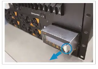
How to Replace a CE-R1
STEP 1: Use the side handle to remove CE R1 from the shelf. RA 3048 rectifier modules are operating normally even without CE R1.
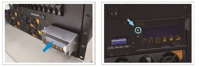
STEP 2: Insert the replacement control unit fully into the shelf until it fits the slot tightly. Wait for a few seconds until the LED on replacement CE R1 shows solid GREEN.
STEP 3: Please set desired parameters on replacement CE R1, or the settings will follow factory default value when inserting new control unit.
In case of any error message or warning LED indicators are on (ex. Flashing organe), please refer to user manual for troubleshooting or contact COTE K local distributor for assistance.
No.33, Sec. 2, Renhe Rd., DaxiDist., Taoyuan City 33548, Taiwan
Phone: 886 3 3891999 Fax: 886 3 3802333
http://www.cotek.com.tw


