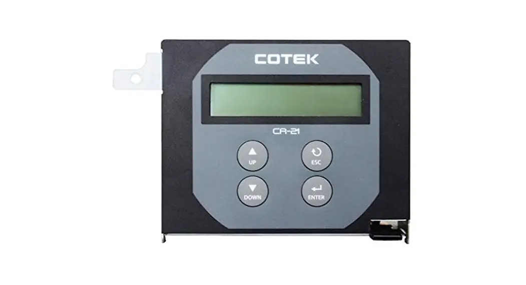
SR-1600 Plus Remote Control
![]()
User Guide For CR-21 PLUS Remote Control
Introduction
1-1. System
The remote is designed to easily and quickly connect Cotek SR-1600 Plus.
The LCD display is used for setting up the inverter, as well as displaying current status or fault messages. Pressing buttons allows you to select a menu item or to save a setting, once it is displayed on the LCD screen.
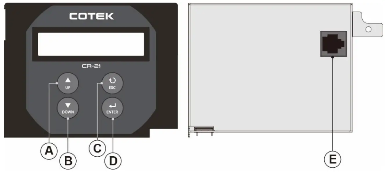
Front and rear Panel introduction
| Description | Function | |
| A | UP | Scroll up |
| B | DOWN | Scroll down |
| C | ESC | Go back to previous page. |
| D | ENTER | Enter next page and save setting value |
| E | RJ-45 port | Connect to the Inverter |
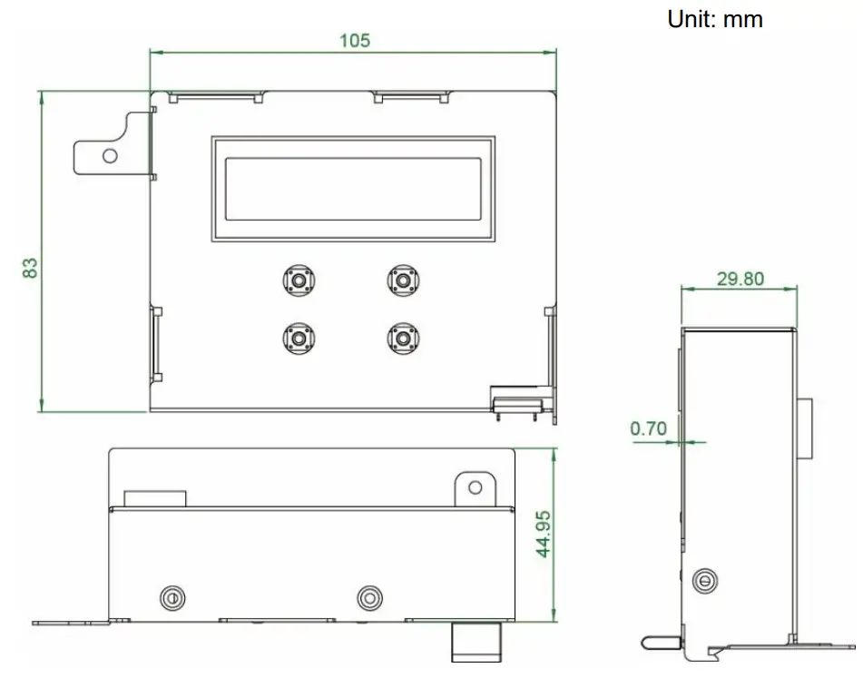
1-2. Mechanical Drawings
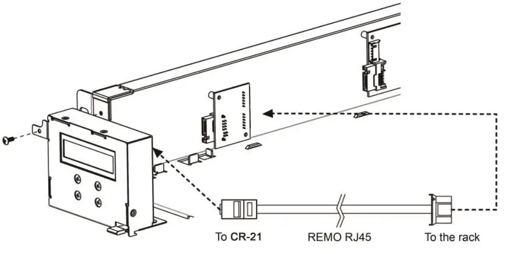
1-3. Hardware Installation
Display tree
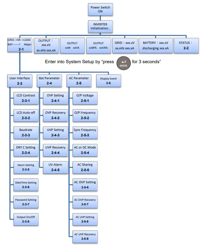
2-1 GRID–>SR–>LOAD BAT——-^ Major
The connection status and Alarm type. For the description of alarm type, (Major /Minor Alarm) please refer to Alarm List in the “SR-1600 Plus User Manual.”
2-2 STATUS:
| STATIS | Possible Cause |
| Normal | The machine is working normally |
| Machine Abnormal | Parallel Fault or Module Fault |
| Grid Abnormal | AC source abnormal |
| Fan Fault | Fan does not work |
| BAT. Low | Under DC voltage protevtion |
| BAT. High | Over DC voltage protection |
| Over Load | The system over the rated capacity(OLA >15sec) |
| Redundancy Fault | Remove the redundancy module or redundant module failure |
| Over Temperature | Temperature is too high |
| BAT. Low Alarm | Under DC voltage Alarm |
| BAT. High Alarm | Over DC voltage Alarm |
| Over Load Alarm | The system over the rated apacity (OLA ) |
| Major Relay On | Pin 12~13 voltage keep high(485 board) |
| Minor Relay On | Pin 14~13 voltage keep high(485 board) |
| Remote OFF | Turn off the machine from dry contact pin1& pin2 |
2-3 User Interface
※The first time use the setting interface, must enter password (000000).
2-3-1 LCD contrast : Sets the LCD screen contrast.
Default = 50% Setting range = 0% ~ 100%
| Setting Menu | SETT<value> |
| LCD Contrast | 0 ~ 100 |
2-3-2 LCD Auto-off : Sets the LCD screen backlight auto off timer
Default = 120 seconds Setting range = 0 ~ 120 seconds
| Setting Menu | SETT<value> |
| LCD Auto-off | 0 ~ 120 |
2-3-3 Baud rate : Default setting:4800
| Setting Menu | SETT<value> |
| RS-485 Baud rate | 1200 |
| 2400 | |
| 4800 | |
| 9600 | |
| 19200 |
2-3-4 Dry contact C setting : Default =1, Setting range = 0~2, default=1.
| Setting Menu | SETT <value> | Description |
| Dry C setting | Disable | Disable |
| DRY C for Major | Selectable extra alarm to go with Major | |
| DRY C for Minor | Selectable extra alarm to go with Minor alarm |
2-3-5 Alarm Setting: Default =1
| Setting Menu | SETT <value> | Description |
| Alarm Setting | Normal | Normal |
| Mute | Mute all alarms | |
| One time | Silent warning for current status |
2-3-6 Date Time Setting: Date yyyy-mm-dd Time hh-mm-ss
YY :year MM :month DD :date HH :hour MM :minute SS :second
2-3-7 Password Setting: 000000~999999, default setting:000000
2-3-8 Output On/Off:
| Setting Menu | SETT <value> | Description |
| Output On/Off | On | Turn on the output |
| Off | Turn off the output |
2-4 Bat Parameter
2-4-1 OVP Setting : Set the Over Voltage Protection (OVP) and shutdown.
Default = 34 VDC @ 24V Model. 68 VDC @ 48V Model
| Model | Setting value range |
| 24V | 30 VDC ~ 34 VDC |
| 48V | 60 VDC ~ 68 VDC |
2-4-2 OVP Recovery : When the DC input voltage is higher than the OVP setting, the SR series shuts down; once the input voltage falls below the set OVP value, the SR series will automatically restart.
Default = 28 VDC @ 24V Model. 56 VDC @ 48V Model
| Model | Setting value range |
| 24V | 26 VDC ~ 30 VDC |
| 48V | 52 VDC ~ 60 VDC |
2-4-3 UVP Setting : Setting Under Voltage Protection (UVP) and shutdown on the inverter operation.
Default= 18 VDC @ 24V Model. 36VDC @ 48V Model
| Model | Setting value range |
| 24V | 18 VDC ~ 25 VDC |
| 48V | 36 VDC ~ 50 VDC |
2-4-4 UVP Recovery : When the DC input voltage is below the set UVP value, the SR series shuts down; once the input voltage rises above the set UVP value, the SR series will automatically restart.
Default= 25 VDC @ 24V Model. 50VDC @ 48V Model
| Model | Setting value range |
| 24V | 23 VDC ~ 27 VDC |
| 48V | 46 VDC ~ 54 VDC |
2-4-5 UV Alarm : Setting Under Voltage (UV) alarm. When the input voltage is lower than the set value, the SR series will sound a “beep” to remind you that the unit is going to shutdown.
Default= 21 VDC @ 24 V Model. 42 VDC @ 48 V Model
| Model | Setting value range |
| 24V | 19 VDC ~ 26 VDC |
| 48V | 38 VDC ~ 52 VDC |
2-5 AC Parameter
2-5-1 O/P Voltage : Setting the SR series output voltage on the inverter
operation. 1xx = 100V, 110V, 115V or 120V ; 2xx = 200V, 220V, 230V or 240V.
| Model | Setting value range |
| 1XX | 97 VAC ~ 127 VAC |
| 2XX | 194 VAC ~ 254 VAC |
2-5-2 O/P Frequency : Setting the SR series output frequency on the inverter
operation. 1xx = 100V, 110V, 115V or 120V ; 2xx = 200V, 220V, 230V or 240V.
| Model | Setting value range |
| 1XX & 2XX | 50 or 60 Hz |
2-5-3 Sync Frequency : Setting SR series output frequency tolerance range on the
inverter operation. 1xx = 100V, 110V, 115V, 120V ; 2xx = 200V, 220V, 230V or 240V.
| Model | Setting value range |
| 1XX & 2XX | 0 Hz ~ 3 Hz |
2-5-4 AC or DC Mode : Default =1, AC Mode is the 1st priority source.
DC Mode:DC is the 1st priority source, and the AC power is the 2nd priority source.
AC Mode:AC is the 1st priority source, and the DC power is the 2nd priority source.
| Mode Priority | SETT<value> |
| DC Mode | 0 |
| AC Mode | 1 |
2-5-5 AC Sharing : Setting range = 10, 20, 30, 40, 50, 60, 70, 80, 90, 100
Default= 100 (Disable)
| Setting Menu | SETT<value> | Description |
| AC Ratio | 10 | AC load 10%, DC load 90% |
| 20 | AC load 20%, DC load 80% | |
| 30 | AC load 30%, DC load 70% | |
| 40 | AC load 40%, DC load 60% | |
| 50 | AC load 50%, DC load 50% | |
| 60 | AC load 60%, DC load 40% | |
| 70 | AC load 70%, DC load 30% | |
| 80 | AC load 80%, DC load 20% | |
| 90 | AC load 90%, DC load 10% | |
| 100 | Disable |
 Note:
Note:
The AC input power must be higher than 300W after assigning DC and AC ratio.
2-5-6 AC OVP Setting : Set the Grid Over Voltage Protection (OVP) and transfer to DC mode(or shuts down without battery).
Default = 130 VAC @ 1xx Model. 260 VAC @ 2xx Model
| Model | Setting value range |
| 1xx | 127.5 VAC ~ 132.5 VAC |
| 2xx | 255 VAC ~ 260 VAC |
2-5-7 AC OVP Recovery : When the AC input voltage is higher than the OVP setting, the SR series transfer to DC mode(or shuts down without battery); once the input voltage falls below the set AC OVP recovery value, the SR series will re-operate in AC mode. Default = 125 VAC @ 1xx Model. 150 VAC @ 2xx Model
| Model | Setting value range |
| 1xx | 120 VAC ~ 127 VAC |
| 2xx | 240 VAC ~254 VAC |
2-5-8 AC UVP Setting : Set the Grid Under Voltage Protection (UVP) and transfer to DC mode(or shuts down without battery).
Default= 90 VAC @ 1xx Model. 180VAC @ 2xx Model
| Model | Setting value range |
| 1xx | 75 VAC ~ 90 VAC |
| 2xx | 150 VAC ~ 180 VAC |
2-5-9 AC UVP Recovery : When the AC input voltage is below the set UVP value, the SR series transfer to DC mode(or shuts down without battery) ; once the input voltage rises above the set UVP recovery value, the SR series will re-operate in AC mode.
Default= 95 VAC @ 1xx Model. 190VAC @ 2xx Model
| Model | Setting value range |
| 1xx | 90.5 VAC ~ 100 VAC |
| 2xx | 181 VAC ~ 200 VAC |
2-6 Display Event
2-6-1Display description
XXX (index) code:XXX (please refer to Error code List)
YY-MMDD-HH-MM-SS (Event time)
※Enter the event page the first information is the latest event
| Model | Setting value range | Model | Setting value range |
| 002 | Output off | 020 | Under DC voltage protection recovery |
| 003 | Output on | 021 | Under DC voltage protection |
| 004 | AC share off | 022 | Overload alarm recovery |
| 005 | AC share on | 023 | Overload alarm |
| 006 | AC mode off | 024 | Overload protection recovery |
| 007 | AC mode on | 025 | Overload protection |
| 008 | DC mode off | 026 | Fan normal |
| 009 | DC mode on | 027 | Fan failure |
| 010 | Grid Volt normal | 028 | Over temperature protection recovery |
| 011 | Grid Volt abnormal | 029 | Over temperature protection |
| 012 | Freq normal | 030 | The Machine was working |
| 013 | Freq abnormal | 031 | Component failed |
| 014 | Over DC voltage alarm recovery | 032 | IC Power voltage normal |
| 015 | Over DC voltage alarm | 033 | IC Power voltage abnormal |
| 016 | Over DC voltage protection recovery | 034 | Insert the module |
| 017 | Over DC voltage protection | 035 | Remove the module |
| 018 | Under DC voltage alarm recovery | 036 | Redundancy _OK |
| 019 | Under DC voltage alarm | 037 | Redundancy_lost |
![]()
No.33, Sec. 2, Renhe Rd., DaxiDist., Taoyuan City 33548, Taiwan
Phone:+886-3-3891999 FAX:+886-3-3802333
http://www.cotek.com.tw
2019.05._A0


